2008 NISSAN TIIDA ESP
[x] Cancel search: ESPPage 560 of 2771
BL-126
< SERVICE INFORMATION >
INTELLIGENT KEY SYSTEM
NG >> Repair or replace Intelligent Key warning buzzer power supply circuit.
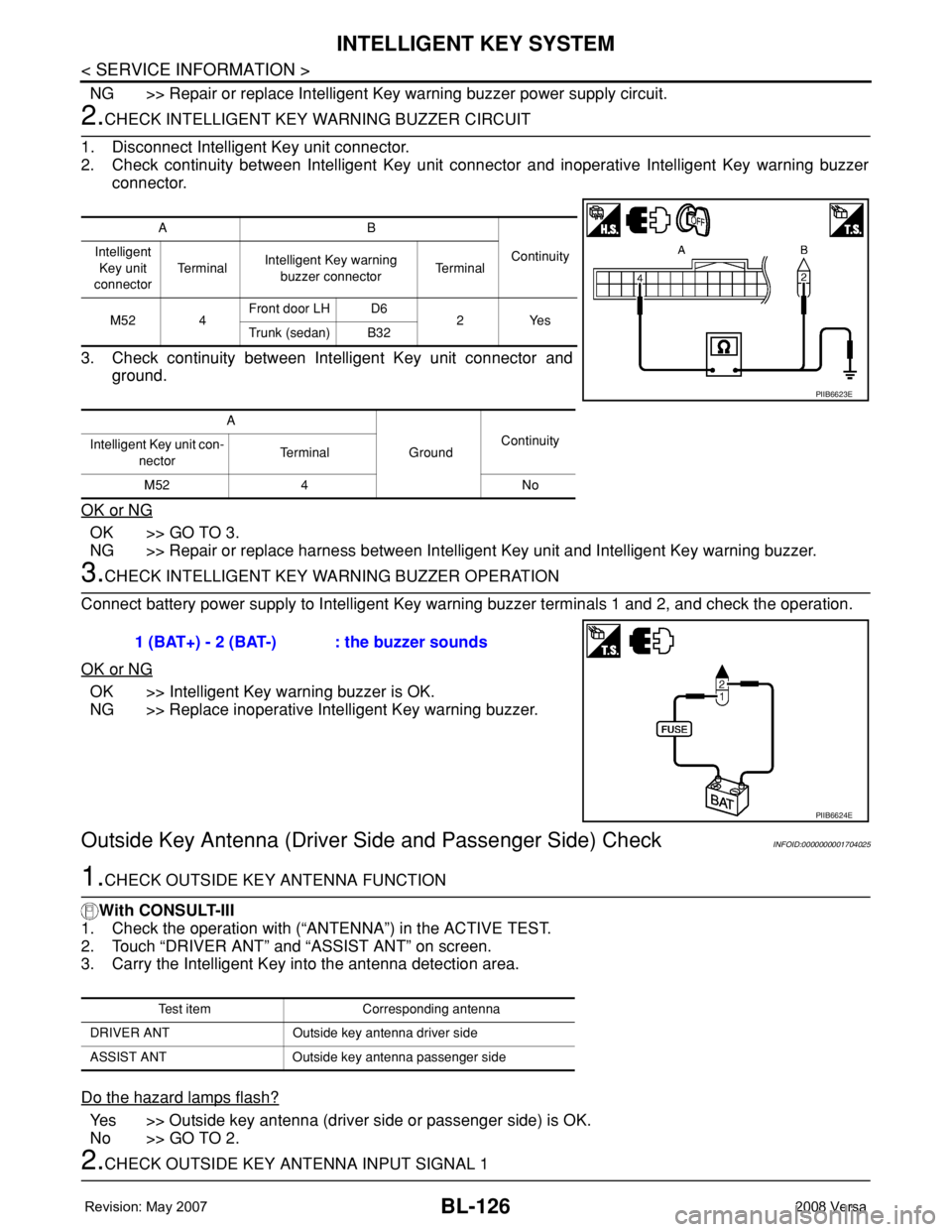
2.CHECK INTELLIGENT KEY WARNING BUZZER CIRCUIT
1. Disconnect Intelligent Key unit connector.
2. Check continuity between Intelligent Key unit connector and inoperative Intelligent Key warning buzzer
connector.
3. Check continuity between Intelligent Key unit connector and
ground.
OK or NG
OK >> GO TO 3.
NG >> Repair or replace harness between Intelligent Key unit and Intelligent Key warning buzzer.
3.CHECK INTELLIGENT KEY WARNING BUZZER OPERATION
Connect battery power supply to Intelligent Key warning buzzer terminals 1 and 2, and check the operation.
OK or NG
OK >> Intelligent Key warning buzzer is OK.
NG >> Replace inoperative Intelligent Key warning buzzer.
Outside Key Antenna (Driver Side and Passenger Side) CheckINFOID:0000000001704025
1.CHECK OUTSIDE KEY ANTENNA FUNCTION
With CONSULT-III
1. Check the operation with (“ANTENNA”) in the ACTIVE TEST.
2. Touch “DRIVER ANT” and “ASSIST ANT” on screen.
3. Carry the Intelligent Key into the antenna detection area.
Do the hazard lamps flash?
Yes >> Outside key antenna (driver side or passenger side) is OK.
No >> GO TO 2.
2.CHECK OUTSIDE KEY ANTENNA INPUT SIGNAL 1
AB
Continuity Intelligent
Key unit
connectorTe r m i n a lIntelligent Key warning
buzzer connectorTe r m i n a l
M52 4Front door LH D6
2Yes
Trunk (sedan) B32
A
GroundContinuity
Intelligent Key unit con-
nectorTerminal
M52 4 No
PIIB6623E
1 (BAT+) - 2 (BAT-) : the buzzer sounds
PIIB6624E
Test item Corresponding antenna
DRIVER ANT Outside key antenna driver side
ASSIST ANT Outside key antenna passenger side
Page 562 of 2771
BL-128
< SERVICE INFORMATION >
INTELLIGENT KEY SYSTEM
OK or NG
OK >> Replace malfunctioning outside key antenna.
NG >> Replace Intelligent Key unit. Refer to BL-142, "
Removal and Installation of Intelligent Key Unit".
Outside Key Antenna (Rear Bumper) CheckINFOID:0000000001704026
1.CHECK REAR BUMPER ANTENNA FUNCTION
With CONSULT-III
1. Check the operation with (“ANTENNA”) in the ACTIVE TEST.
2. Touch “BD/TR ANT” on screen.
3. Carry the Intelligent Key into the antenna detection area.
Do the hazard lamps flash?
Yes >> Rear bumper antenna is OK.
No >> GO TO 2.
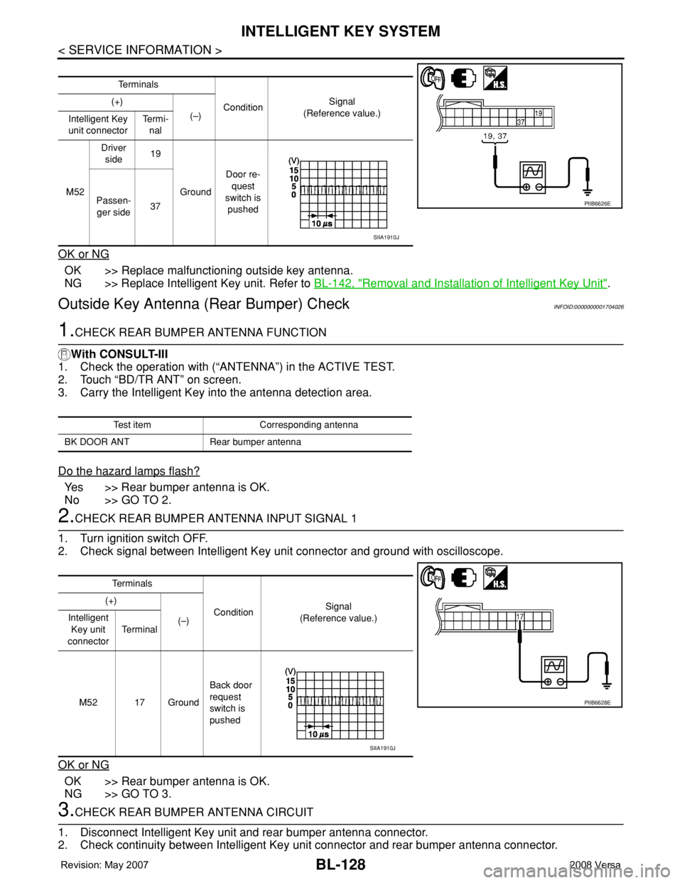
2.CHECK REAR BUMPER ANTENNA INPUT SIGNAL 1
1. Turn ignition switch OFF.
2. Check signal between Intelligent Key unit connector and ground with oscilloscope.
OK or NG
OK >> Rear bumper antenna is OK.
NG >> GO TO 3.
3.CHECK REAR BUMPER ANTENNA CIRCUIT
1. Disconnect Intelligent Key unit and rear bumper antenna connector.
2. Check continuity between Intelligent Key unit connector and rear bumper antenna connector.
Te r m i n a l s
ConditionSignal
(Reference value.) (+)
(–)
Intelligent Key
unit connectorTe r m i -
nal
M52Driver
side19
GroundDoor re-
quest
switch is
pushed Passen-
ger side37
PIIB6626E
SIIA1910J
Test item Corresponding antenna
BK DOOR ANT Rear bumper antenna
Te r m i n a l s
ConditionSignal
(Reference value.) (+)
(–) Intelligent
Key unit
connectorTe r m i n a l
M52 17 GroundBack door
request
switch is
pushed
PIIB6628E
SIIA1910J
Page 773 of 2771
![NISSAN TIIDA 2008 Service Repair Manual BRC-8
< SERVICE INFORMATION >[ABS]
TROUBLE DIAGNOSIS
TROUBLE DIAGNOSIS
How to Perform Trouble Diagnosis for Quick and Accurate RepairINFOID:0000000001703831
INTRODUCTION
The ABS system has an electron NISSAN TIIDA 2008 Service Repair Manual BRC-8
< SERVICE INFORMATION >[ABS]
TROUBLE DIAGNOSIS
TROUBLE DIAGNOSIS
How to Perform Trouble Diagnosis for Quick and Accurate RepairINFOID:0000000001703831
INTRODUCTION
The ABS system has an electron](/manual-img/5/57399/w960_57399-772.png)
BRC-8
< SERVICE INFORMATION >[ABS]
TROUBLE DIAGNOSIS
TROUBLE DIAGNOSIS
How to Perform Trouble Diagnosis for Quick and Accurate RepairINFOID:0000000001703831
INTRODUCTION
The ABS system has an electronic control unit to control major func-
tions. The control unit accepts input signals from sensors and con-
trols actuator operation. It is also important to check for air leaks in
the booster or brake and vacuum lines, lack of brake fluid, or other
malfunctions in the brake system.
It is much more difficult to diagnose a malfunction that occurs inter-
mittently rather than continuously. Most intermittent conditions are
caused by poor electrical connections or damaged wiring. In this
case, careful checking of suspicious circuits may help prevent the
replacement of good parts.
A visual check only may not find the cause of the malfunction, so a
road test should be performed.
Before undertaking actual checks, take just a few minutes to talk with
a customer who approaches with an ABS complaint. The customer
is a very good source of information, especially for intermittent condi-
tions. Through the talks with the customer, find out what symptoms
are present and under what conditions they occur.
Start your diagnosis by looking for “conventional” malfunctions first.
This is one of the best ways to troubleshoot brake malfunctions on
an ABS equipped vehicle. Also check related Service Bulletins for
information.
SEF233G
SEF234G
Page 850 of 2771
PRECAUTIONS
CVT-11
< SERVICE INFORMATION >
D
E
F
G
H
I
J
K
L
MA
B
CVT
N
O
P
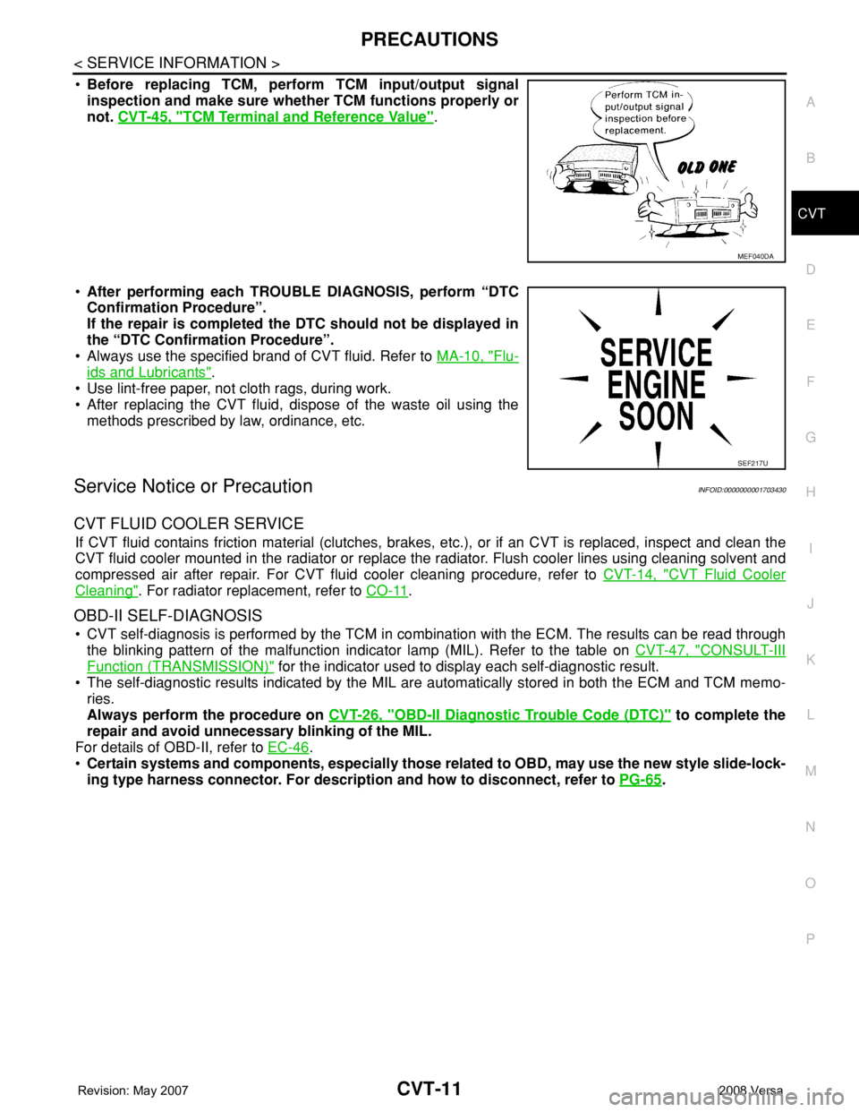
•Before replacing TCM, perform TCM input/output signal
inspection and make sure whether TCM functions properly or
not. CVT-45, "
TCM Terminal and Reference Value".
•After performing each TROUBLE DIAGNOSIS, perform “DTC
Confirmation Procedure”.
If the repair is completed the DTC should not be displayed in
the “DTC Confirmation Procedure”.
• Always use the specified brand of CVT fluid. Refer to MA-10, "
Flu-
ids and Lubricants".
• Use lint-free paper, not cloth rags, during work.
• After replacing the CVT fluid, dispose of the waste oil using the
methods prescribed by law, ordinance, etc.
Service Notice or PrecautionINFOID:0000000001703430
CVT FLUID COOLER SERVICE
If CVT fluid contains friction material (clutches, brakes, etc.), or if an CVT is replaced, inspect and clean the
CVT fluid cooler mounted in the radiator or replace the radiator. Flush cooler lines using cleaning solvent and
compressed air after repair. For CVT fluid cooler cleaning procedure, refer to CVT-14, "
CVT Fluid Cooler
Cleaning". For radiator replacement, refer to CO-11.
OBD-II SELF-DIAGNOSIS
• CVT self-diagnosis is performed by the TCM in combination with the ECM. The results can be read through
the blinking pattern of the malfunction indicator lamp (MIL). Refer to the table on CVT-47, "
CONSULT-III
Function (TRANSMISSION)" for the indicator used to display each self-diagnostic result.
• The self-diagnostic results indicated by the MIL are automatically stored in both the ECM and TCM memo-
ries.
Always perform the procedure on CVT-26, "
OBD-II Diagnostic Trouble Code (DTC)" to complete the
repair and avoid unnecessary blinking of the MIL.
For details of OBD-II, refer to EC-46
.
•Certain systems and components, especially those related to OBD, may use the new style slide-lock-
ing type harness connector. For description and how to disconnect, refer to PG-65
.
MEF040DA
SEF217U
Page 859 of 2771

CVT-20
< SERVICE INFORMATION >
CVT SYSTEM
Hydraulic Control System
INFOID:0000000001703438
TCM FunctionINFOID:0000000001703439
The function of the TCM is to:
• Receive input signals sent from various switches and sensors.
• Determine required line pressure, shifting point, and lock-up operation.
• Send required output signals to the step motor and the respective solenoids.
CONTROL SYSTEM OUTLINE
The CVT senses vehicle operating conditions through various sensors. It always controls the optimum shift
position and reduces shifting and lock-up shocks.
SCIA1807E
SENSORS (or SIGNAL)
⇒TCM
⇒ACTUATORS
PNP switch
Accelerator pedal position signal
Closed throttle position signal
Engine speed signal
CVT fluid temperature sensor
Vehicle speed signal
Overdrive control signal
Stop lamp switch signal
Primary speed sensor
Secondary speed sensor
Primary pressure sensor
Secondary pressure sensorShift control
Line pressure control
Primary pressure control
Secondary pressure control
Lock-up control
Engine brake control
Vehicle speed control
Fail-safe control
Self-diagnosis
CONSULT-III communication
line
Duet-EA control
CAN system
On board diagnosisSte p m ot or
Torque converter clutch solenoid
valve
Lock-up select solenoid valve
Line pressure solenoid valve
Secondary pressure solenoid
valve
Shift position indicator
O/D OFF indicator lamp
Starter relay
Page 865 of 2771
CVT-26
< SERVICE INFORMATION >
ON BOARD DIAGNOSTIC (OBD) SYSTEM
ON BOARD DIAGNOSTIC (OBD) SYSTEM
IntroductionINFOID:0000000001703446
The CVT system has two self-diagnostic systems.
The first is the emission-related on board diagnostic system (OBD-II) performed by the TCM in combination
with the ECM. The malfunction is indicated by the MIL (malfunction indicator lamp) and is stored as a DTC in
the ECM memory, and the TCM memory.
The second is the TCM original self-diagnosis performed by the TCM. The malfunction is stored in the TCM
memory. The detected items are overlapped with OBD-II self-diagnostic items. For detail, refer to CVT-47,
"CONSULT-III Function (TRANSMISSION)".
OBD-II Function for CVT SystemINFOID:0000000001703447
The ECM provides emission-related on board diagnostic (OBD-II) functions for the CVT system. One function
is to receive a signal from the TCM used with OBD-related parts of the CVT system. The signal is sent to the
ECM when a malfunction occurs in the corresponding OBD-related part. The other function is to indicate a
diagnostic result by means of the MIL (malfunction indicator lamp) on the instrument panel. Sensors, switches
and solenoid valves are used as sensing elements.
The MIL automatically illuminates in One or Two Trip Detection Logic when a malfunction is sensed in relation
to CVT system parts.
One or Two Trip Detection Logic of OBD-IIINFOID:0000000001703448
ONE TRIP DETECTION LOGIC
If a malfunction is sensed during the first test drive, the MIL will illuminate and the malfunction will be stored in
the ECM memory as a DTC. The TCM is not provided with such a memory function.
TWO TRIP DETECTION LOGIC
When a malfunction is sensed during the first test drive, it is stored in the ECM memory as a 1st trip DTC
(diagnostic trouble code) or 1st trip freeze frame data. At this point, the MIL will not illuminate. — 1st trip
If the same malfunction as that experienced during the first test drive is sensed during the second test drive,
the MIL will illuminate. — 2nd trip
The “trip” in the “One or Two Trip Detection Logic” means a driving mode in which self-diagnosis is performed
during vehicle operation.
OBD-II Diagnostic Trouble Code (DTC)INFOID:0000000001703449
HOW TO READ DTC AND 1ST TRIP DTC
DTC and 1st trip DTC can be read by the following methods.
( with CONSULT-III or GST) CONSULT-III or GST (Generic Scan Tool) Examples: P0705, P0720 etc.
These DTC are prescribed by SAE J2012.
(CONSULT-III also displays the malfunctioning component or system.)
•1st trip DTC No. is the same as DTC No.
•Output of the diagnostic trouble code indicates that the indicated circuit has a malfunction. How-
ever, in case of the Mode II and GST, they do not indicate whether the malfunction is still occurring or
occurred in the past and returned to normal.
CONSULT-III can identify them as shown below, therefore, CONSULT-III (if available) is recom-
mended.
DTC or 1st trip DTC of a malfunction is displayed in SELF-DIAGNOSTIC RESULTS mode for “ENGINE” with
CONSULT-III. Time data indicates how many times the vehicle was driven after the last detection of a DTC.
If the DTC is being detected currently, the time data will be “0”.
If a 1st trip DTC is stored in the ECM, the time data will be “1t”.
Freeze Frame Data and 1st Trip Freeze Frame Data
Page 869 of 2771

CVT-30
< SERVICE INFORMATION >
TROUBLE DIAGNOSIS
If an unexpected signal is sent from the solenoid to the TCM, the CVT lock-up select solenoid is turned OFF to
cancel the lock-up.
TCM Power Supply (Memory Back-up)
Transaxle assembly is protected by limiting the engine torque when the memory back-up power supply (for
controlling) from the battery is not supplied to TCM. Normal statues is restored when turning the ignition switch
OFF to ON after the normal power supply.
How to Perform Trouble Diagnosis for Quick and Accurate RepairINFOID:0000000001703453
INTRODUCTION
The TCM receives a signal from the vehicle speed sensor, PNP switch and provides shift control or lock-up
control via CVT solenoid valves.
The TCM also communicates with the ECM by means of a signal
sent from sensing elements used with the OBD-related parts of the
CVT system for malfunction-diagnostic purposes. The TCM is capa-
ble of diagnosing malfunctioning parts while the ECM can store mal-
functions in its memory.
Input and output signals must always be correct and stable in the
operation of the CVT system. The CVT system must be in good
operating condition and be free of valve seizure, solenoid valve mal-
function, etc.
It is much more difficult to diagnose an error that occurs intermit-
tently rather than continuously. Most intermittent errors are caused
by poor electric connections or improper wiring. In this case, careful
checking of suspected circuits may help prevent the replacement of
good parts.
A visual check only may not find the cause of the errors. A road test
with CONSULT-III (or GST) or a circuit tester connected should be
performed. Follow the "WORK FLOW" .
Before undertaking actual checks, take a few minutes to talk with a
customer who approaches with a driveability complaint. The cus-
tomer can supply good information about such errors, especially
intermittent ones. Find out what symptoms are present and under
what conditions they occur. A “DIAGNOSTIC WORKSHEET” as
shown on the example (Refer to "Diagnostic Worksheet Chart" )
should be used.
Start your diagnosis by looking for “conventional” errors first. This will
help troubleshoot driveability errors on an electronically controlled
engine vehicle.
Also check related Service bulletins.
WORK FLOW
A good understanding of the malfunction conditions can make troubleshooting faster and more accurate.
In general, each customer feels differently about a malfunction. It is important to fully understand the symp-
toms or conditions for a customer complaint.
Make good use of the two sheets provided, "Information From Customer" and "Diagnostic Worksheet Chart" ,
to perform the best troubleshooting possible.
Work Flow Chart
SAT631IB
SAT632I
SEF234G
Page 925 of 2771
CVT-86
< SERVICE INFORMATION >
DTC P0725 ENGINE SPEED SIGNAL
• If DTC of CAN communication line is detected, go to CVT-56.
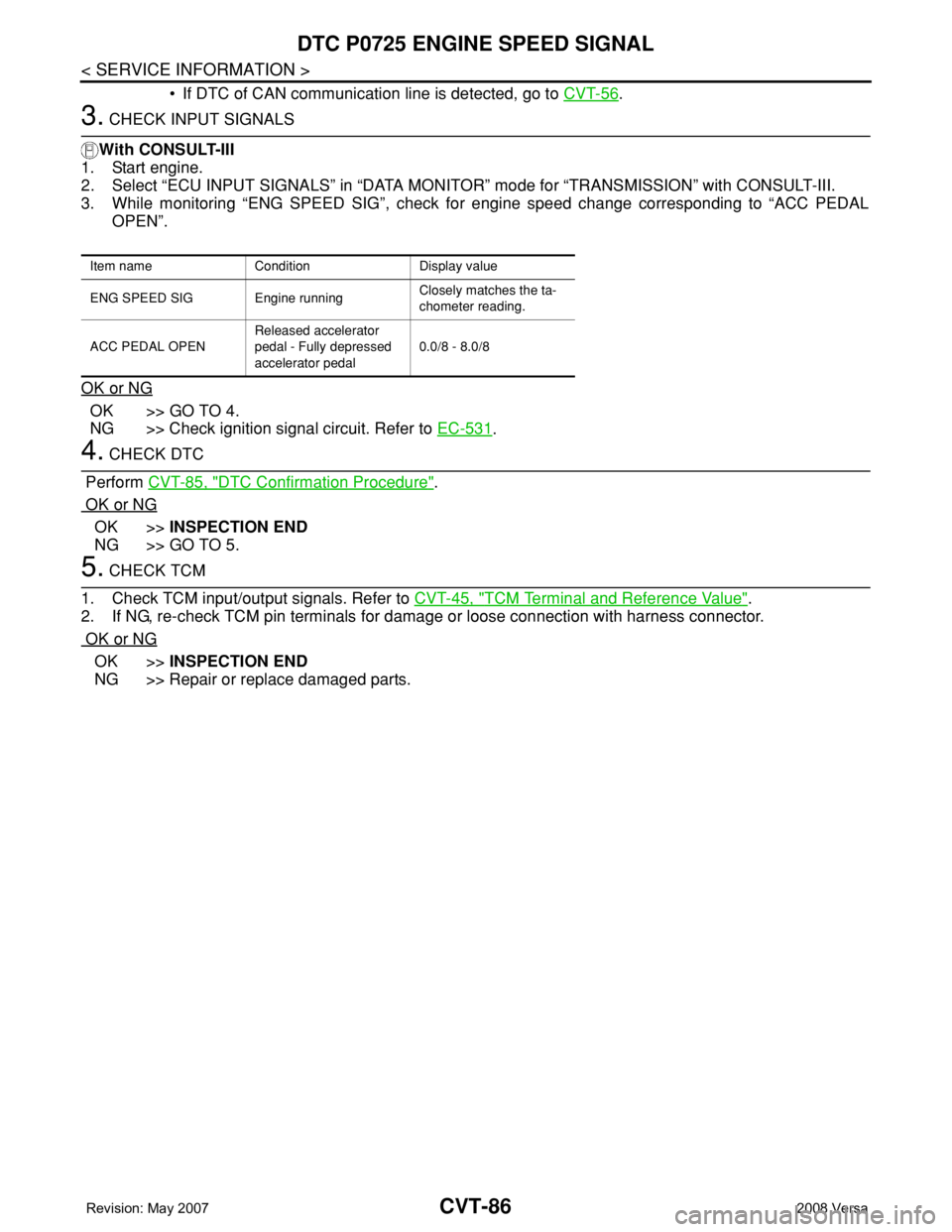
3. CHECK INPUT SIGNALS
With CONSULT-III
1. Start engine.
2. Select “ECU INPUT SIGNALS” in “DATA MONITOR” mode for “TRANSMISSION” with CONSULT-III.
3. While monitoring “ENG SPEED SIG”, check for engine speed change corresponding to “ACC PEDAL
OPEN”.
OK or NG
OK >> GO TO 4.
NG >> Check ignition signal circuit. Refer to EC-531
.
4. CHECK DTC
Perform CVT-85, "
DTC Confirmation Procedure".
OK or NG
OK >>INSPECTION END
NG >> GO TO 5.
5. CHECK TCM
1. Check TCM input/output signals. Refer to CVT-45, "
TCM Terminal and Reference Value".
2. If NG, re-check TCM pin terminals for damage or loose connection with harness connector.
OK or NG
OK >>INSPECTION END
NG >> Repair or replace damaged parts.
Item name Condition Display value
ENG SPEED SIG Engine runningClosely matches the ta-
chometer reading.
ACC PEDAL OPENReleased accelerator
pedal - Fully depressed
accelerator pedal0.0/8 - 8.0/8