2008 NISSAN TIIDA ESP
[x] Cancel search: ESPPage 330 of 2771
AT-318
< SERVICE INFORMATION >
ASSEMBLY
ASSEMBLY
Assembly (1)INFOID:0000000001703391
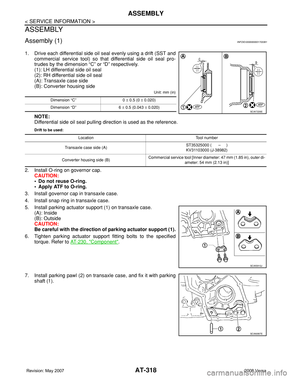
1. Drive each differential side oil seal evenly using a drift (SST and
commercial service tool) so that differential side oil seal pro-
trudes by the dimension “C” or “D” respectively.
(1): LH differential side oil seal
(2): RH differential side oil seal
(A): Transaxle case side
(B): Converter housing side
Unit: mm (in)
NOTE:
Differential side oil seal pulling direction is used as the reference.
Drift to be used:
2. Install O-ring on governor cap.
CAUTION:
• Do not reuse O-ring.
• Apply ATF to O-ring.
3. Install governor cap in transaxle case.
4. Install snap ring in transaxle case.
5. Install parking actuator support (1) on transaxle case.
(A): Inside
(B): Outside
CAUTION:
Be careful with the direction of parking actuator support (1).
6. Tighten parking actuator support fitting bolts to the specified
torque. Refer to AT-230, "
Component".
7. Install parking pawl (2) on transaxle case, and fix it with parking
shaft (1).
Dimension “C” 0 ± 0.5 (0 ± 0.020)
Dimension “D” 6 ± 0.5 (0.043 ± 0.020)
SCIA7226E
Location Tool number
Transaxle case side (A)ST35325000 ( – )
KV31103000 (J-38982)
Converter housing side (B)Commercial service tool [Inner diameter: 47 mm (1.85 in), outer di-
ameter: 54 mm (2.13 in)]
SCIA5910J
SCIA6997E
Page 381 of 2771
AV-22
< SERVICE INFORMATION >
AUDIO
Power Supply Circuit Inspection
INFOID:0000000001704663
1.CHECK FUSE
Check that the following fuses of the subwoofer (premium system) and audio unit are not blown.
OK or NG
OK >> GO TO 2.
NG >> If fuse is blown, be sure to eliminate cause of blown fuse before installing new fuse. Refer to PG-
3 .
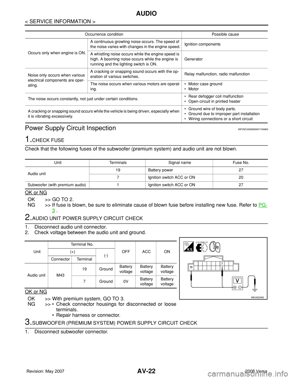
2.AUDIO UNIT POWER SUPPLY CIRCUIT CHECK
1. Disconnect audio unit connector.
2. Check voltage between the audio unit and ground.
OK or NG
OK >> With premium system, GO TO 3.
NG >> • Check connector housings for disconnected or loose
terminals.
• Repair harness or connector.
3.SUBWOOFER (PREMIUM SYSTEM) POWER SUPPLY CIRCUIT CHECK
1. Disconnect subwoofer connector.
Occurrence condition Possible cause
Occurs only when engine is ON.A continuous growling noise occurs. The speed of
the noise varies with changes in the engine speed.Ignition components
A whistling noise occurs while the engine speed is
high. A booming noise occurs while the engine is
running and the lighting switch is ON.Generator
Noise only occurs when various
electrical components are oper-
ating.A cracking or snapping sound occurs with the op-
eration of various switches.Relay malfunction, radio malfunction
The noise occurs when various motors are operat-
ing.• Motor case ground
• Motor
The noise occurs constantly, not just under certain conditions.• Rear defogger coil malfunction
• Open circuit in printed heater
A cracking or snapping sound occurs while the vehicle is being driven, especially when
it is vibrating excessively.• Ground wire of body parts.
• Ground due to improper part installation
• Wiring connections or a short circuit
Unit Terminals Signal name Fuse No.
Audio unit19 Battery power 27
7 Ignition switch ACC or ON 20
Subwoofer (with premium audio) 1 Ignition switch ACC or ON 27
UnitTe r m i n a l N o .
OFF ACC ON (+)
(-)
Connector Terminal
Audio unit M4319 GroundBattery
voltageBattery
voltageBattery
voltage
7Ground0VBattery
voltageBattery
voltage
WKIA5345E
Page 419 of 2771
BCM (BODY CONTROL MODULE)
BCS-3
< SERVICE INFORMATION >
C
D
E
F
G
H
I
J
L
MA
B
BCS
N
O
P
BCM (BODY CONTROL MODULE)
System DescriptionINFOID:0000000001704584
BCM (body control module) controls the operation of various electrical units installed on the vehicle.
BCM FUNCTION
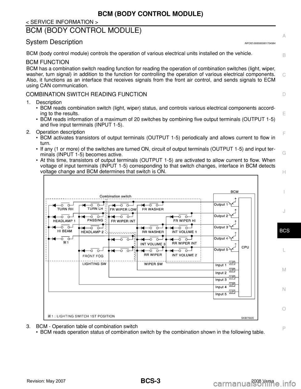
BCM has a combination switch reading function for reading the operation of combination switches (light, wiper,
washer, turn signal) in addition to the function for controlling the operation of various electrical components.
Also, it functions as an interface that receives signals from the front air control, and sends signals to ECM
using CAN communication.
COMBINATION SWITCH READING FUNCTION
1. Description
• BCM reads combination switch (light, wiper) status, and controls various electrical components accord-
ing to the results.
• BCM reads information of a maximum of 20 switches by combining five output terminals (OUTPUT 1-5)
and five input terminals (INPUT 1-5).
2. Operation description
• BCM activates transistors of output terminals (OUTPUT 1-5) periodically and allows current to flow in
turn.
• If any (1 or more) of the switches are turned ON, circuit of output terminals (OUTPUT 1-5) and input ter-
minals (INPUT 1-5) becomes active.
• At this time, transistors of output terminals (OUTPUT 1-5) are activated to allow current to flow. When
voltage of input terminals (INPUT 1-5) corresponding to that switch changes, interface in BCM detects
voltage change and BCM determines that switch is ON.
3. BCM - Operation table of combination switch
• BCM reads operation status of combination switch by the combination shown in the following table.
SKIB7592E
Page 441 of 2771
SQUEAK AND RATTLE TROUBLE DIAGNOSES
BL-7
< SERVICE INFORMATION >
C
D
E
F
G
H
J
K
L
MA
B
BL
N
O
P
SQUEAK AND RATTLE TROUBLE DIAGNOSES
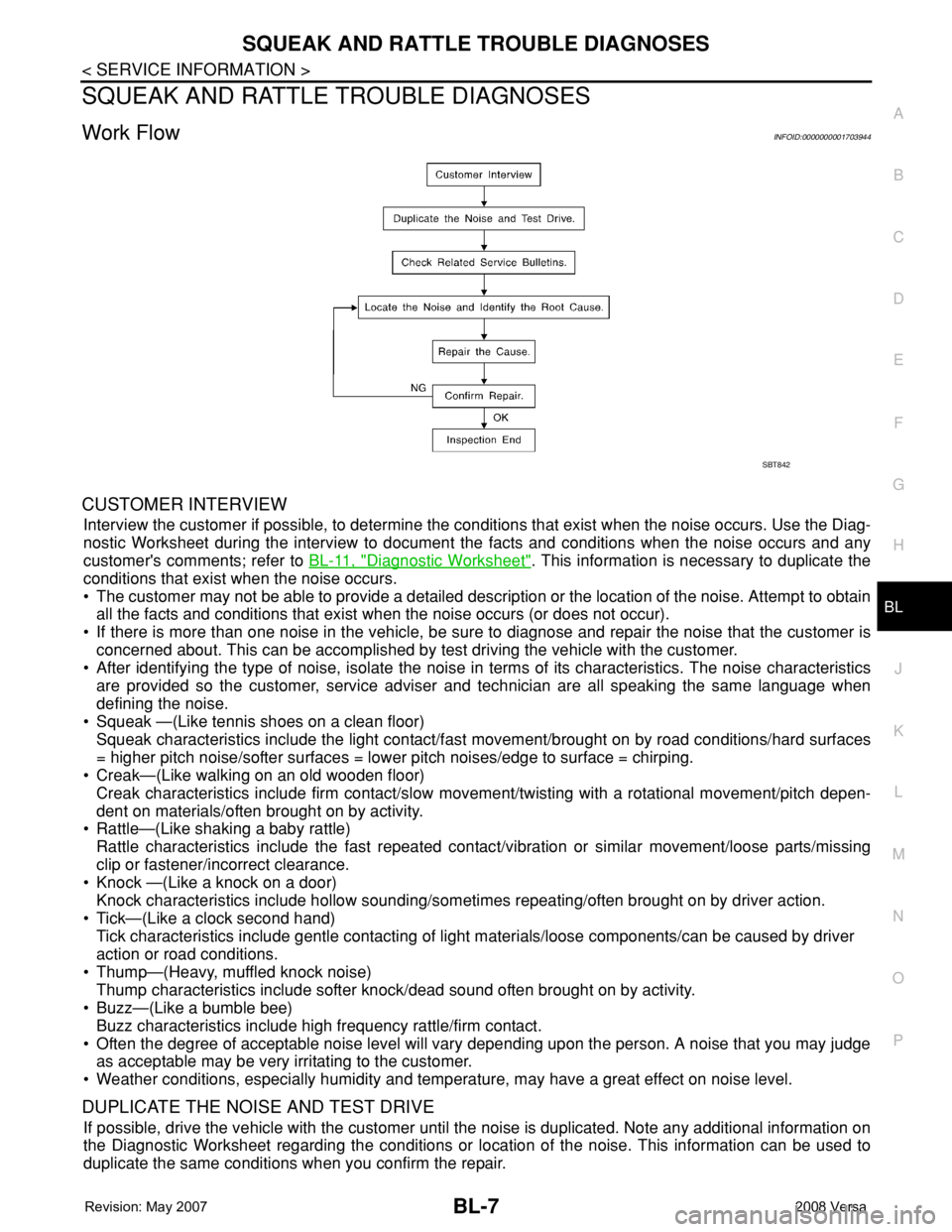
Work FlowINFOID:0000000001703944
CUSTOMER INTERVIEW
Interview the customer if possible, to determine the conditions that exist when the noise occurs. Use the Diag-
nostic Worksheet during the interview to document the facts and conditions when the noise occurs and any
customer's comments; refer to BL-11, "
Diagnostic Worksheet". This information is necessary to duplicate the
conditions that exist when the noise occurs.
• The customer may not be able to provide a detailed description or the location of the noise. Attempt to obtain
all the facts and conditions that exist when the noise occurs (or does not occur).
• If there is more than one noise in the vehicle, be sure to diagnose and repair the noise that the customer is
concerned about. This can be accomplished by test driving the vehicle with the customer.
• After identifying the type of noise, isolate the noise in terms of its characteristics. The noise characteristics
are provided so the customer, service adviser and technician are all speaking the same language when
defining the noise.
• Squeak —(Like tennis shoes on a clean floor)
Squeak characteristics include the light contact/fast movement/brought on by road conditions/hard surfaces
= higher pitch noise/softer surfaces = lower pitch noises/edge to surface = chirping.
• Creak—(Like walking on an old wooden floor)
Creak characteristics include firm contact/slow movement/twisting with a rotational movement/pitch depen-
dent on materials/often brought on by activity.
• Rattle—(Like shaking a baby rattle)
Rattle characteristics include the fast repeated contact/vibration or similar movement/loose parts/missing
clip or fastener/incorrect clearance.
• Knock —(Like a knock on a door)
Knock characteristics include hollow sounding/sometimes repeating/often brought on by driver action.
• Tick—(Like a clock second hand)
Tick characteristics include gentle contacting of light materials/loose components/can be caused by driver
action or road conditions.
• Thump—(Heavy, muffled knock noise)
Thump characteristics include softer knock/dead sound often brought on by activity.
• Buzz—(Like a bumble bee)
Buzz characteristics include high frequency rattle/firm contact.
• Often the degree of acceptable noise level will vary depending upon the person. A noise that you may judge
as acceptable may be very irritating to the customer.
• Weather conditions, especially humidity and temperature, may have a great effect on noise level.
DUPLICATE THE NOISE AND TEST DRIVE
If possible, drive the vehicle with the customer until the noise is duplicated. Note any additional information on
the Diagnostic Worksheet regarding the conditions or location of the noise. This information can be used to
duplicate the same conditions when you confirm the repair.
SBT842
Page 495 of 2771
REMOTE KEYLESS ENTRY SYSTEM
BL-61
< SERVICE INFORMATION >
C
D
E
F
G
H
J
K
L
MA
B
BL
N
O
P
Keyfob Battery and Function CheckINFOID:0000000001703984
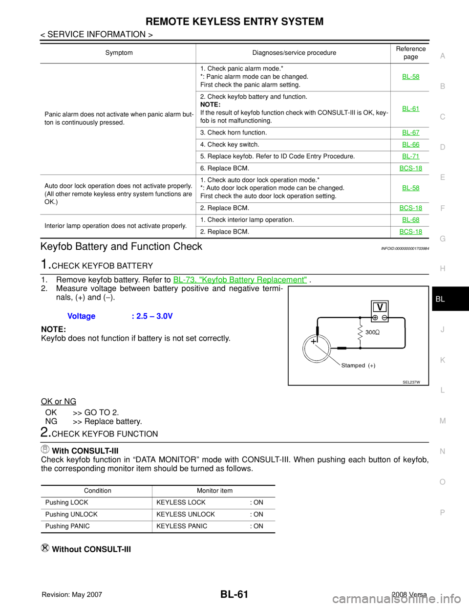
1.CHECK KEYFOB BATTERY
1. Remove keyfob battery. Refer to BL-73, "
Keyfob Battery Replacement" .
2. Measure voltage between battery positive and negative termi-
nals, (+) and (−).
NOTE:
Keyfob does not function if battery is not set correctly.
OK or NG
OK >> GO TO 2.
NG >> Replace battery.
2.CHECK KEYFOB FUNCTION
With CONSULT-III
Check keyfob function in “DATA MONITOR” mode with CONSULT-III. When pushing each button of keyfob,
the corresponding monitor item should be turned as follows.
Without CONSULT-III
Panic alarm does not activate when panic alarm but-
ton is continuously pressed.1. Check panic alarm mode.*
*: Panic alarm mode can be changed.
First check the panic alarm setting.BL-58
2. Check keyfob battery and function.
NOTE:
If the result of keyfob function check with CONSULT-III is OK, key-
fob is not malfunctioning.BL-61
3. Check horn function.BL-67
4. Check key switch.BL-66
5. Replace keyfob. Refer to ID Code Entry Procedure.BL-71
6. Replace BCM.BCS-18
Auto door lock operation does not activate properly.
(All other remote keyless entry system functions are
OK.)1. Check auto door lock operation mode.*
*: Auto door lock operation mode can be changed.
First check the auto door lock operation setting.BL-58
2. Replace BCM.BCS-18
Interior lamp operation does not activate properly.1. Check interior lamp operation.BL-682. Replace BCM.BCS-18
Symptom Diagnoses/service procedureReference
page
Voltage : 2.5 – 3.0V
SEL237W
Condition Monitor item
Pushing LOCK KEYLESS LOCK : ON
Pushing UNLOCK KEYLESS UNLOCK : ON
Pushing PANIC KEYLESS PANIC : ON
Page 505 of 2771
REMOTE KEYLESS ENTRY SYSTEM
BL-71
< SERVICE INFORMATION >
C
D
E
F
G
H
J
K
L
MA
B
BL
N
O
P
NG >> Repair or replace harness.
Keyfob Function (Lock) CheckINFOID:0000000001703993
1.CHECK KEYFOB FUNCTION
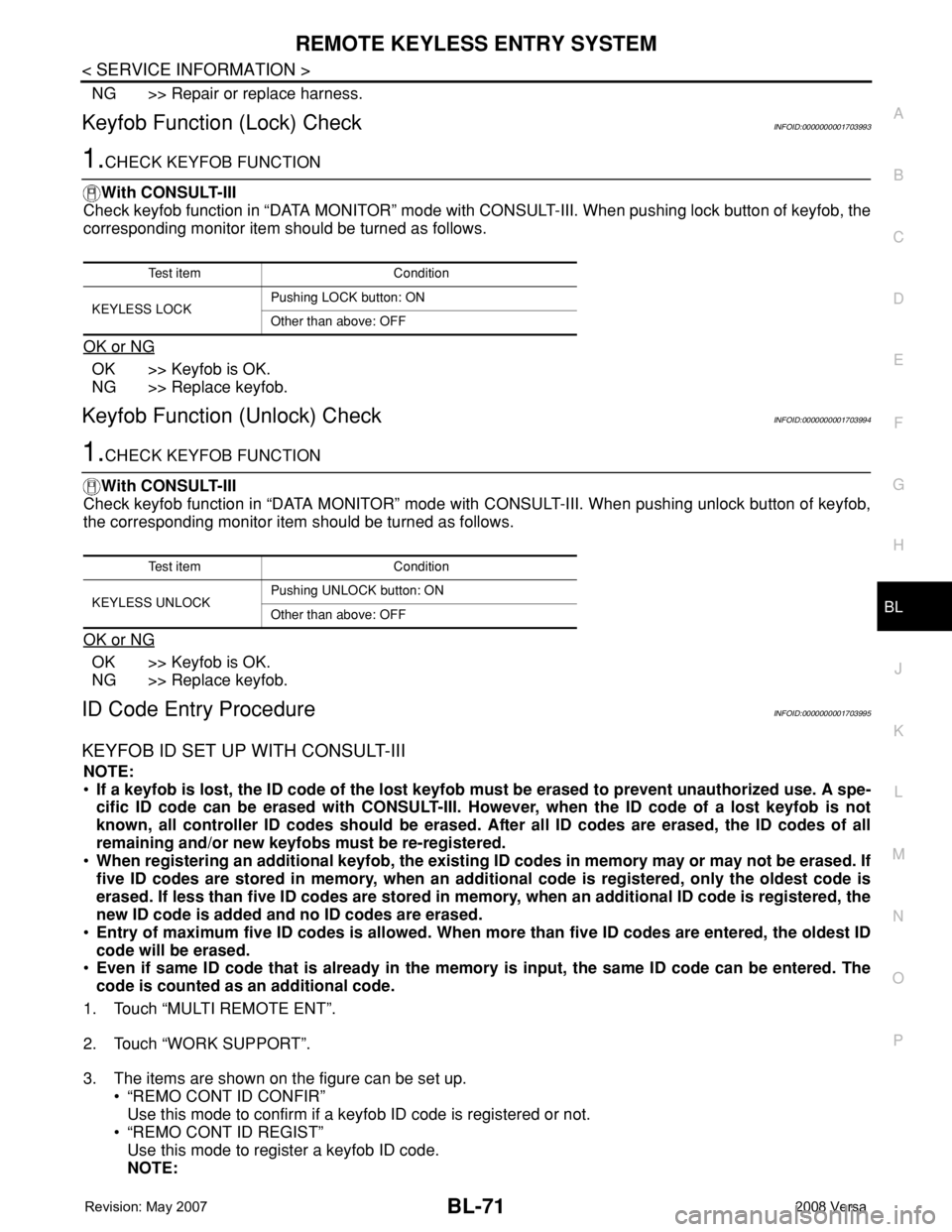
With CONSULT-III
Check keyfob function in “DATA MONITOR” mode with CONSULT-III. When pushing lock button of keyfob, the
corresponding monitor item should be turned as follows.
OK or NG
OK >> Keyfob is OK.
NG >> Replace keyfob.
Keyfob Function (Unlock) CheckINFOID:0000000001703994
1.CHECK KEYFOB FUNCTION
With CONSULT-III
Check keyfob function in “DATA MONITOR” mode with CONSULT-III. When pushing unlock button of keyfob,
the corresponding monitor item should be turned as follows.
OK or NG
OK >> Keyfob is OK.
NG >> Replace keyfob.
ID Code Entry ProcedureINFOID:0000000001703995
KEYFOB ID SET UP WITH CONSULT-III
NOTE:
•If a keyfob is lost, the ID code of the lost keyfob must be erased to prevent unauthorized use. A spe-
cific ID code can be erased with CONSULT-III. However, when the ID code of a lost keyfob is not
known, all controller ID codes should be erased. After all ID codes are erased, the ID codes of all
remaining and/or new keyfobs must be re-registered.
•When registering an additional keyfob, the existing ID codes in memory may or may not be erased. If
five ID codes are stored in memory, when an additional code is registered, only the oldest code is
erased. If less than five ID codes are stored in memory, when an additional ID code is registered, the
new ID code is added and no ID codes are erased.
•Entry of maximum five ID codes is allowed. When more than five ID codes are entered, the oldest ID
code will be erased.
•Even if same ID code that is already in the memory is input, the same ID code can be entered. The
code is counted as an additional code.
1. Touch “MULTI REMOTE ENT”.
2. Touch “WORK SUPPORT”.
3. The items are shown on the figure can be set up.
• “REMO CONT ID CONFIR”
Use this mode to confirm if a keyfob ID code is registered or not.
• “REMO CONT ID REGIST”
Use this mode to register a keyfob ID code.
NOTE:
Test item Condition
KEYLESS LOCKPushing LOCK button: ON
Other than above: OFF
Test item Condition
KEYLESS UNLOCKPushing UNLOCK button: ON
Other than above: OFF
Page 510 of 2771

BL-76
< SERVICE INFORMATION >
INTELLIGENT KEY SYSTEM
System Description
INFOID:0000000001703999
• The Intelligent Key system is a system that makes it possible to lock and unlock the door locks (door lock/
unlock function), and start the engine (engine start function) by carrying around the Intelligent Key (without
some key operation), which operates based on the results of electronic ID verification using two-way com-
munications between the Intelligent Key and the vehicle (Intelligent Key unit).
• Vehicles equipped with a manual transmission include a key interlock solenoid located in the steering col-
umn to prevent accidental shut-off of the ignition switch and locking of the steering wheel during driving con-
dition when the vehicle is moving.
CAUTION:
The driver should always carry the Intelligent Key
• Operation of the remote controller buttons on the Intelligent Key also provides the same functions as the
remote control entry system. (Remote keyless entry functions)
• If an action that does not meet the operating conditions of the Intelligent Key system is taken, the buzzer
goes off to inform the driver. (Warning chime functions)
• When a door lock is locked or unlocked with request switch or remote controller button operation, the hazard
lamps flash and the buzzer (outside vehicle) sounds (Hazard and buzzer reminder function).
• Even if the Intelligent Key battery is completely discharged, the door locks can be locked and unlocked and
the engine started with the mechanical key built into the Intelligent Key.
• The settings for each function can be changed with the CONSULT-III.
• If an Intelligent Key is lost, a new Intelligent Key can be registered. A maximum of 4 Intelligent Keys can be
registered.
• It has been made possible to diagnose the system and register an Intelligent Key with the CONSULT-III.
DOOR LOCK/UNLOCK FUNCTION
Only when pressing the request switch, it is possible to lock and unlock the door by carrying around the Intelli-
gent Key (without some key operation).
System Diagram
Operation Description
• When the Intelligent Key unit detects that each request switch is pressed, it starts the outside key antenna
and inside key antenna corresponding to the pressed request switch and sends the request signal to the
Intelligent Key. And then, make sure that the Intelligent Key is near door.
• If the Intelligent Key is within the outside key antenna detection area, it receives the request signal and
sends the key ID signal to the Intelligent Key unit.
• Intelligent Key unit receives the key ID signal and compares it with the registered key ID.
• If the key ID check result is OK, the Intelligent Key unit sends the door lock/unlock request signal to BCM
(Body control module) via CAN communication line.
• Intelligent Key unit sends the door lock/unlock signal and sounds Intelligent Key warning buzzer (lock: 2
times, unlock: 1 time) at the same time.
• When BCM receives the door lock/unlock signal, it operates door lock actuator and flashes the hazard warn-
ing lamp (lock: 2 times, unlock: 1 time) at the same time as reminder.
Operation Condition
If the following conditions are not satisfied, door lock/unlock operations are not performed even if the request
switch is operated.
LIIA2926E
Page 534 of 2771
BL-100
< SERVICE INFORMATION >
INTELLIGENT KEY SYSTEM
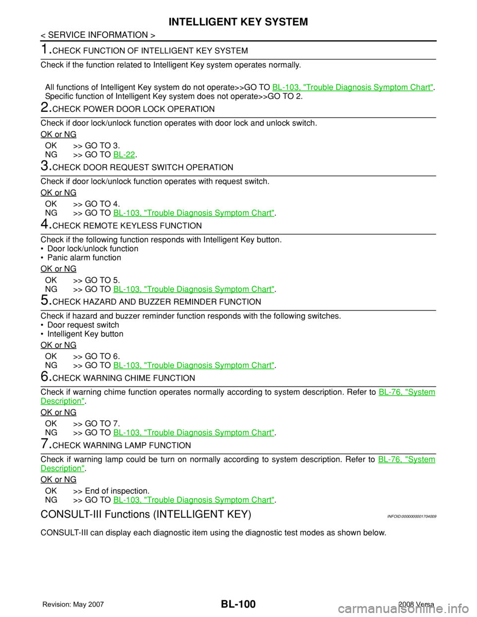
1.CHECK FUNCTION OF INTELLIGENT KEY SYSTEM
Check if the function related to Intelligent Key system operates normally.
All functions of Intelligent Key system do not operate>>GO TO BL-103, "
Trouble Diagnosis Symptom Chart".
Specific function of Intelligent Key system does not operate>>GO TO 2.
2.CHECK POWER DOOR LOCK OPERATION
Check if door lock/unlock function operates with door lock and unlock switch.
OK or NG
OK >> GO TO 3.
NG >> GO TO BL-22
.
3.CHECK DOOR REQUEST SWITCH OPERATION
Check if door lock/unlock function operates with request switch.
OK or NG
OK >> GO TO 4.
NG >> GO TO BL-103, "
Trouble Diagnosis Symptom Chart".
4.CHECK REMOTE KEYLESS FUNCTION
Check if the following function responds with Intelligent Key button.
• Door lock/unlock function
• Panic alarm function
OK or NG
OK >> GO TO 5.
NG >> GO TO BL-103, "
Trouble Diagnosis Symptom Chart".
5.CHECK HAZARD AND BUZZER REMINDER FUNCTION
Check if hazard and buzzer reminder function responds with the following switches.
• Door request switch
• Intelligent Key button
OK or NG
OK >> GO TO 6.
NG >> GO TO BL-103, "
Trouble Diagnosis Symptom Chart".
6.CHECK WARNING CHIME FUNCTION
Check if warning chime function operates normally according to system description. Refer to BL-76, "
System
Description".
OK or NG
OK >> GO TO 7.
NG >> GO TO BL-103, "
Trouble Diagnosis Symptom Chart".
7.CHECK WARNING LAMP FUNCTION
Check if warning lamp could be turn on normally according to system description. Refer to BL-76, "
System
Description".
OK or NG
OK >> End of inspection.
NG >> GO TO BL-103, "
Trouble Diagnosis Symptom Chart".
CONSULT-III Functions (INTELLIGENT KEY)INFOID:0000000001704009
CONSULT-III can display each diagnostic item using the diagnostic test modes as shown below.