2008 NISSAN TIIDA ESP
[x] Cancel search: ESPPage 1248 of 2771
EC-174
< SERVICE INFORMATION >
DTC P0101 MAF SENSOR
b. If NG, repair or replace malfunctioning part and perform step 2 to 4 again.
If OK, go to next step.
6. Turn ignition switch OFF.
7. Disconnect mass air flow sensor harness connector and reconnect it again.
8. Perform step 2 to 4 again.
9. If NG, clean or replace mass air flow sensor.
Without CONSULT-II
1. Reconnect all harness connectors disconnected.
2. Start engine and warm it up to normal operating temperature.
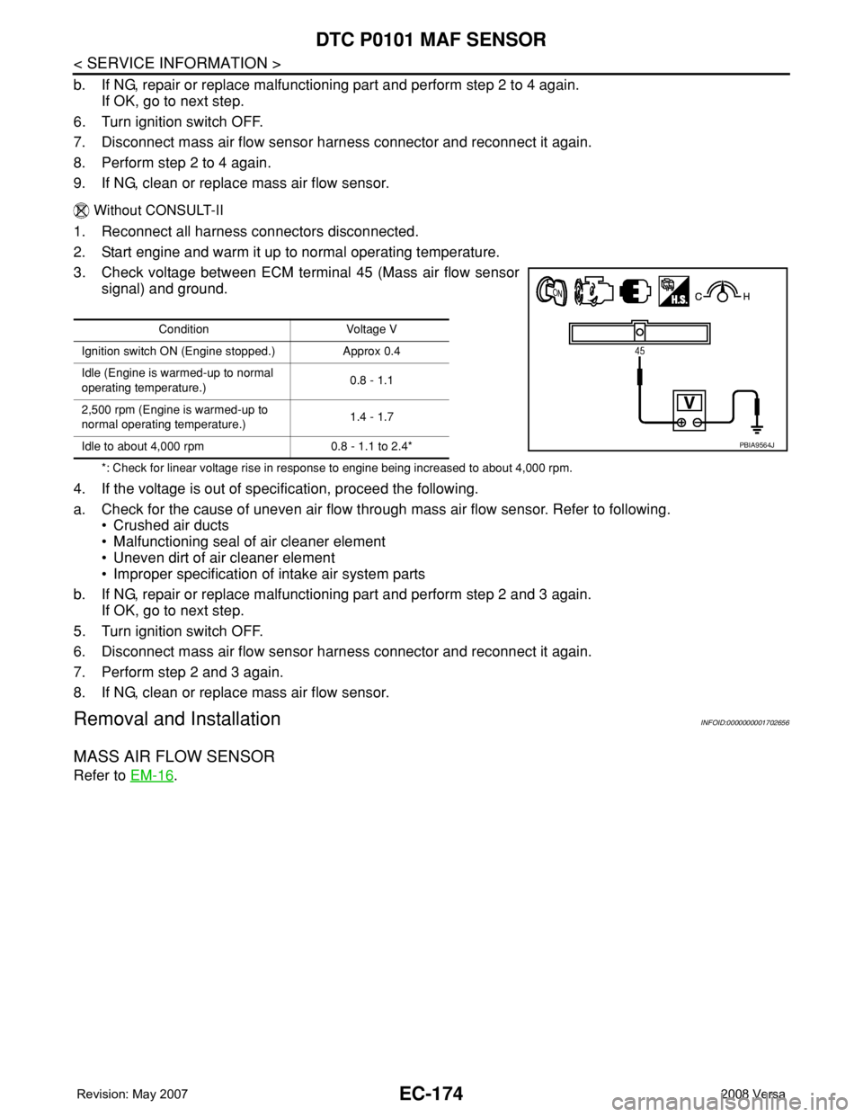
3. Check voltage between ECM terminal 45 (Mass air flow sensor
signal) and ground.
*: Check for linear voltage rise in response to engine being increased to about 4,000 rpm.
4. If the voltage is out of specification, proceed the following.
a. Check for the cause of uneven air flow through mass air flow sensor. Refer to following.
• Crushed air ducts
• Malfunctioning seal of air cleaner element
• Uneven dirt of air cleaner element
• Improper specification of intake air system parts
b. If NG, repair or replace malfunctioning part and perform step 2 and 3 again.
If OK, go to next step.
5. Turn ignition switch OFF.
6. Disconnect mass air flow sensor harness connector and reconnect it again.
7. Perform step 2 and 3 again.
8. If NG, clean or replace mass air flow sensor.
Removal and InstallationINFOID:0000000001702656
MASS AIR FLOW SENSOR
Refer to EM-16.
Condition Voltage V
Ignition switch ON (Engine stopped.) Approx 0.4
Idle (Engine is warmed-up to normal
operating temperature.)0.8 - 1.1
2,500 rpm (Engine is warmed-up to
normal operating temperature.)1.4 - 1.7
Idle to about 4,000 rpm 0.8 - 1.1 to 2.4*
PBIA9564J
Page 1254 of 2771
EC-180
< SERVICE INFORMATION >
DTC P0102, P0103 MAF SENSOR
2. Also check harness for short to ground and short to power.
OK or NG
OK >> GO TO 8.
NG >> Repair open circuit or short to ground or short to power in harness or connectors.
8.CHECK MASS AIR FLOW SENSOR
Refer to EC-180, "
Component Inspection".
OK or NG
OK >> GO TO 9.
NG >> Replace mass air flow sensor.
9.CHECK INTERMITTENT INCIDENT
Refer to EC-136
.
>>INSPECTION END
Component InspectionINFOID:0000000001702663
MASS AIR FLOW SENSOR
With CONSULT-II
1. Reconnect all harness connectors disconnected.
2. Start engine and warm it up to normal operating temperature.
3. Connect CONSULT-II and select “DATA MONITOR” mode.
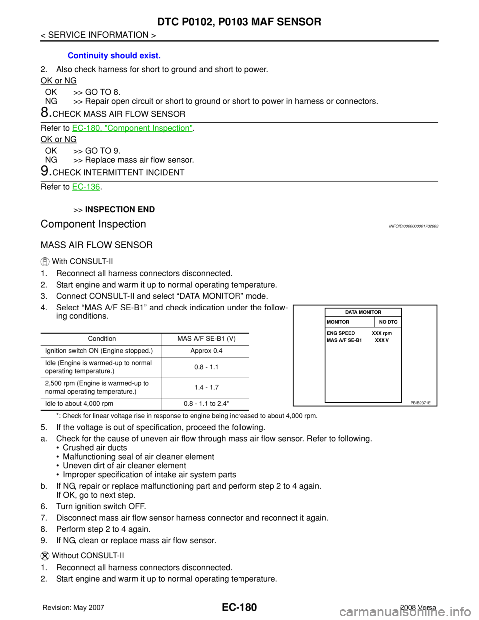
4. Select “MAS A/F SE-B1” and check indication under the follow-
ing conditions.
*: Check for linear voltage rise in response to engine being increased to about 4,000 rpm.
5. If the voltage is out of specification, proceed the following.
a. Check for the cause of uneven air flow through mass air flow sensor. Refer to following.
• Crushed air ducts
• Malfunctioning seal of air cleaner element
• Uneven dirt of air cleaner element
• Improper specification of intake air system parts
b. If NG, repair or replace malfunctioning part and perform step 2 to 4 again.
If OK, go to next step.
6. Turn ignition switch OFF.
7. Disconnect mass air flow sensor harness connector and reconnect it again.
8. Perform step 2 to 4 again.
9. If NG, clean or replace mass air flow sensor.
Without CONSULT-II
1. Reconnect all harness connectors disconnected.
2. Start engine and warm it up to normal operating temperature.Continuity should exist.
Condition MAS A/F SE-B1 (V)
Ignition switch ON (Engine stopped.) Approx 0.4
Idle (Engine is warmed-up to normal
operating temperature.)0.8 - 1.1
2,500 rpm (Engine is warmed-up to
normal operating temperature.)1.4 - 1.7
Idle to about 4,000 rpm 0.8 - 1.1 to 2.4*
PBIB2371E
Page 1255 of 2771
DTC P0102, P0103 MAF SENSOR
EC-181
< SERVICE INFORMATION >
C
D
E
F
G
H
I
J
K
L
MA
EC
N
P O
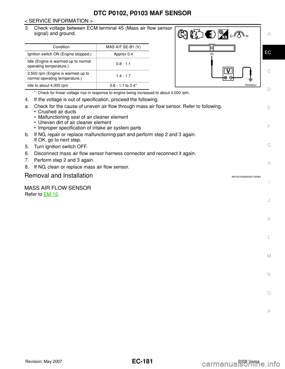
3. Check voltage between ECM terminal 45 (Mass air flow sensor
signal) and ground.
*: Check for linear voltage rise in response to engine being increased to about 4,000 rpm.
4. If the voltage is out of specification, proceed the following.
a. Check for the cause of uneven air flow through mass air flow sensor. Refer to following.
• Crushed air ducts
• Malfunctioning seal of air cleaner element
• Uneven dirt of air cleaner element
• Improper specification of intake air system parts
b. If NG, repair or replace malfunctioning part and perform step 2 and 3 again.
If OK, go to next step.
5. Turn ignition switch OFF.
6. Disconnect mass air flow sensor harness connector and reconnect it again.
7. Perform step 2 and 3 again.
8. If NG, clean or replace mass air flow sensor.
Removal and InstallationINFOID:0000000001702664
MASS AIR FLOW SENSOR
Refer to EM-16.
Condition MAS A/F SE-B1 (V)
Ignition switch ON (Engine stopped.) Approx 0.4
Idle (Engine is warmed-up to normal
operating temperature.)0.8 - 1.1
2,500 rpm (Engine is warmed-up to
normal operating temperature.)1.4 - 1.7
Idle to about 4,000 rpm 0.8 - 1.1 to 2.4*
PBIA9564J
Page 1256 of 2771
EC-182
< SERVICE INFORMATION >
DTC P0112, P0113 IAT SENSOR
DTC P0112, P0113 IAT SENSOR
Component DescriptionINFOID:0000000001702665
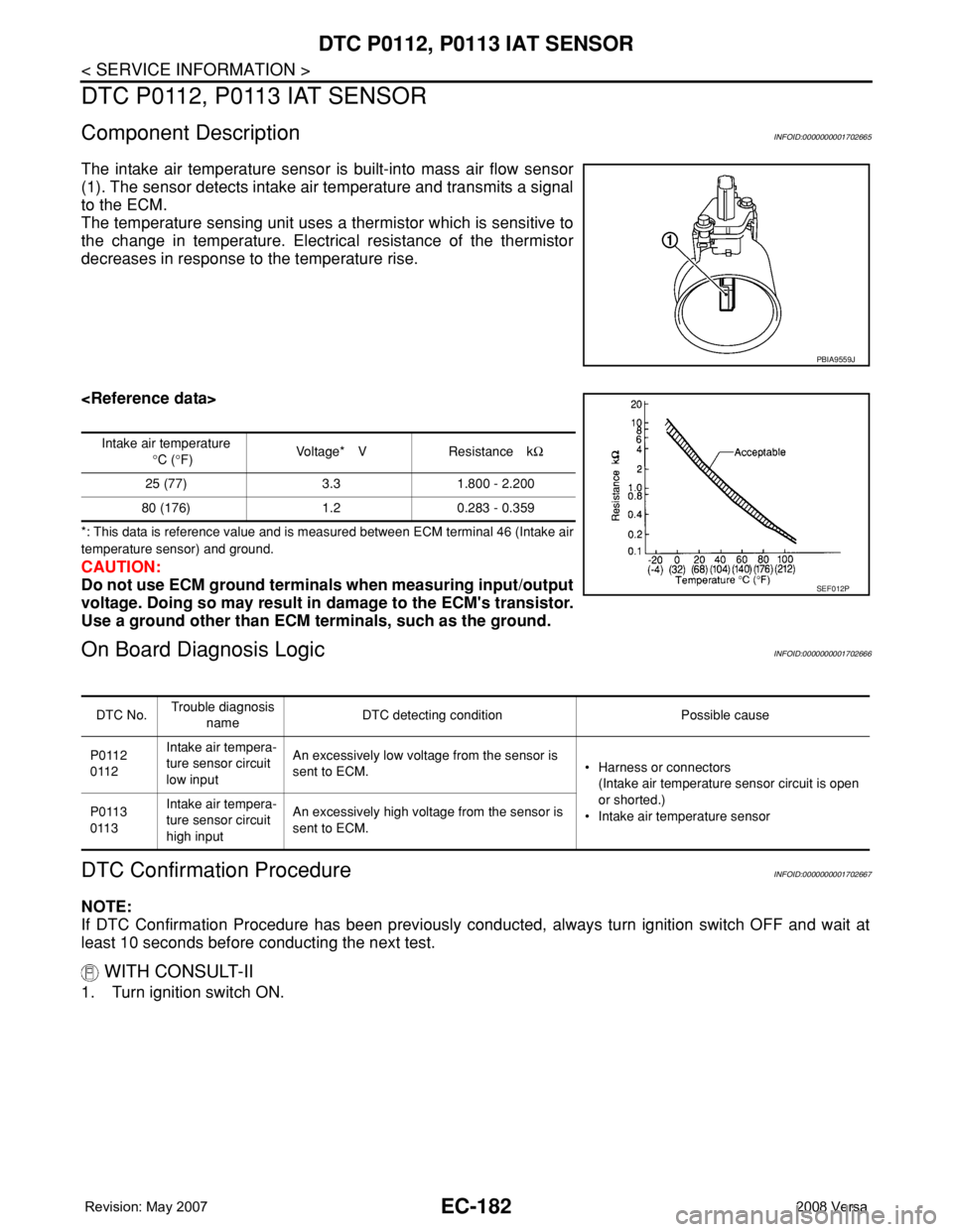
The intake air temperature sensor is built-into mass air flow sensor
(1). The sensor detects intake air temperature and transmits a signal
to the ECM.
The temperature sensing unit uses a thermistor which is sensitive to
the change in temperature. Electrical resistance of the thermistor
decreases in response to the temperature rise.
*: This data is reference value and is measured between ECM terminal 46 (Intake air
temperature sensor) and ground.
CAUTION:
Do not use ECM ground terminals when measuring input/output
voltage. Doing so may result in damage to the ECM's transistor.
Use a ground other than ECM terminals, such as the ground.
On Board Diagnosis LogicINFOID:0000000001702666
DTC Confirmation ProcedureINFOID:0000000001702667
NOTE:
If DTC Confirmation Procedure has been previously conducted, always turn ignition switch OFF and wait at
least 10 seconds before conducting the next test.
WITH CONSULT-II
1. Turn ignition switch ON.
PBIA9559J
Intake air temperature
°C (°F)Voltage* V Resistance kΩ
25 (77) 3.3 1.800 - 2.200
80 (176) 1.2 0.283 - 0.359
SEF012P
DTC No.Trouble diagnosis
nameDTC detecting condition Possible cause
P0112
0112Intake air tempera-
ture sensor circuit
low inputAn excessively low voltage from the sensor is
sent to ECM.• Harness or connectors
(Intake air temperature sensor circuit is open
or shorted.)
• Intake air temperature sensor P0113
0113Intake air tempera-
ture sensor circuit
high inputAn excessively high voltage from the sensor is
sent to ECM.
Page 1266 of 2771
EC-192
< SERVICE INFORMATION >
DTC P0122, P0123 TP SENSOR
DTC P0122, P0123 TP SENSOR
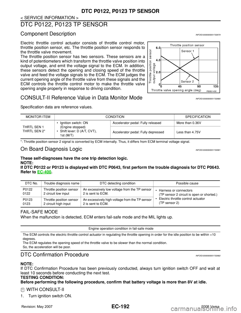
Component DescriptionINFOID:0000000001702679
Electric throttle control actuator consists of throttle control motor,
throttle position sensor, etc. The throttle position sensor responds to
the throttle valve movement.
The throttle position sensor has two sensors. These sensors are a
kind of potentiometers which transform the throttle valve position into
output voltage, and emit the voltage signal to the ECM. In addition,
these sensors detect the opening and closing speed of the throttle
valve and feed the voltage signals to the ECM. The ECM judges the
current opening angle of the throttle valve from these signals and the
ECM controls the throttle control motor to make the throttle valve
opening angle properly in response to driving condition.
CONSULT-II Reference Value in Data Monitor ModeINFOID:0000000001702680
Specification data are reference values.
*: Throttle position sensor 2 signal is converted by ECM internally. Thus, it differs from ECM terminal voltage signal.
On Board Diagnosis LogicINFOID:0000000001702681
These self-diagnoses have the one trip detection logic.
NOTE:
If DTC P0122 or P0123 is displayed with DTC P0643, first perform the trouble diagnosis for DTC P0643.
Refer to EC-400
.
FAIL-SAFE MODE
When the malfunction is detected, ECM enters fail-safe mode and the MIL lights up.
DTC Confirmation ProcedureINFOID:0000000001702682
NOTE:
If DTC Confirmation Procedure has been previously conducted, always turn ignition switch OFF and wait at
least 10 seconds before conducting the next test.
TESTING CONDITION:
Before performing the following procedure, confirm that battery voltage is more than 8V at idle.
WITH CONSULT-II
1. Turn ignition switch ON.
PBIB0145E
MONITOR ITEM CONDITION SPECIFICATION
THRTL SEN 1
THRTL SEN 2*• Ignition switch: ON
(Engine stopped)
• Shift lever: D (A/T, CVT),
1st (M/T)Accelerator pedal: Fully released More than 0.36V
Accelerator pedal: Fully depressed Less than 4.75V
DTC No. Trouble diagnosis name DTC detecting condition Possible cause
P0122
0122Throttle position sensor
2 circuit low inputAn excessively low voltage from the TP sensor
2 is sent to ECM.• Harness or connectors
(TP sensor 2 circuit is open or shorted.)
• Electric throttle control actuator
(TP sensor 2) P0123
0123Throttle position sensor
2 circuit high inputAn excessively high voltage from the TP sensor
2 is sent to ECM.
Engine operation condition in fail-safe mode
The ECM controls the electric throttle control actuator in regulating the throttle opening in order for the idle position to be within +10
degrees.
The ECM regulates the opening speed of the throttle valve to be slower than the normal condition.
So, the acceleration will be poor.
Page 1275 of 2771
DTC P0127 IAT SENSOR
EC-201
< SERVICE INFORMATION >
C
D
E
F
G
H
I
J
K
L
MA
EC
N
P O
DTC P0127 IAT SENSOR
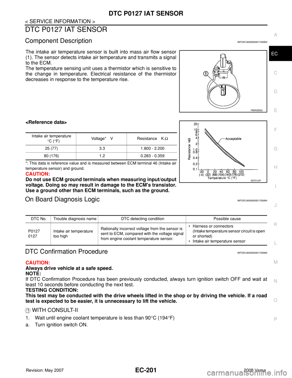
Component DescriptionINFOID:0000000001702693
The intake air temperature sensor is built into mass air flow sensor
(1). The sensor detects intake air temperature and transmits a signal
to the ECM.
The temperature sensing unit uses a thermistor which is sensitive to
the change in temperature. Electrical resistance of the thermistor
decreases in response to the temperature rise.
*: This data is reference value and is measured between ECM terminal 46 (Intake air
temperature sensor) and ground.
CAUTION:
Do not use ECM ground terminals when measuring input/output
voltage. Doing so may result in damage to the ECM's transistor.
Use a ground other than ECM terminals, such as the ground.
On Board Diagnosis LogicINFOID:0000000001702694
DTC Confirmation ProcedureINFOID:0000000001702695
CAUTION:
Always drive vehicle at a safe speed.
NOTE:
If DTC Confirmation Procedure has been previously conducted, always turn ignition switch OFF and wait at
least 10 seconds before conducting the next test.
TESTING CONDITION:
This test may be conducted with the drive wheels lifted in the shop or by driving the vehicle. If a road
test is expected to be easier, it is unnecessary to lift the vehicle.
WITH CONSULT-II
1. Wait until engine coolant temperature is less than 90°C (194°F)
a. Turn ignition switch ON.
PBIA9559J
Intake air temperature
°C (°F)Voltage* V Resistance K.Ω
25 (77) 3.3 1.800 - 2.200
80 (176) 1.2 0.283 - 0.359
SEF012P
DTC No. Trouble diagnosis name DTC detecting condition Possible cause
P0127
0127Intake air temperature
too highRationally incorrect voltage from the sensor is
sent to ECM, compared with the voltage signal
from engine coolant temperature sensor.• Harness or connectors
(Intake temperature sensor circuit is open
or shorted)
• Intake air temperature sensor
Page 1299 of 2771
DTC P0133 A/F SENSOR 1
EC-225
< SERVICE INFORMATION >
C
D
E
F
G
H
I
J
K
L
MA
EC
N
P O
DTC P0133 A/F SENSOR 1
Component DescriptionINFOID:0000000001702726
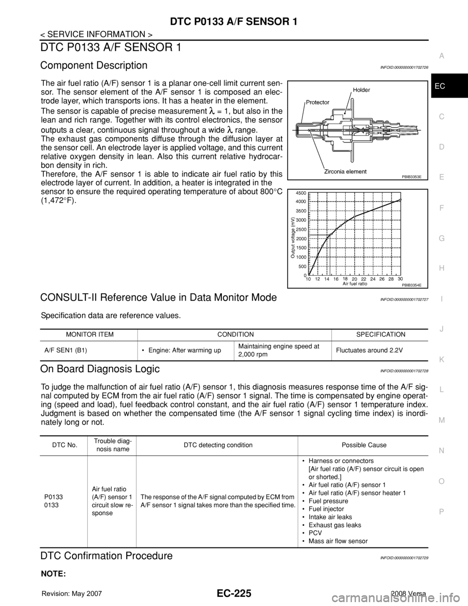
The air fuel ratio (A/F) sensor 1 is a planar one-cell limit current sen-
sor. The sensor element of the A/F sensor 1 is composed an elec-
trode layer, which transports ions. It has a heater in the element.
The sensor is capable of precise measurement = 1, but also in the
lean and rich range. Together with its control electronics, the sensor
outputs a clear, continuous signal throughout a wide range.
The exhaust gas components diffuse through the diffusion layer at
the sensor cell. An electrode layer is applied voltage, and this current
relative oxygen density in lean. Also this current relative hydrocar-
bon density in rich.
Therefore, the A/F sensor 1 is able to indicate air fuel ratio by this
electrode layer of current. In addition, a heater is integrated in the
sensor to ensure the required operating temperature of about 800°C
(1,472°F).
CONSULT-II Reference Value in Data Monitor ModeINFOID:0000000001702727
Specification data are reference values.
On Board Diagnosis LogicINFOID:0000000001702728
To judge the malfunction of air fuel ratio (A/F) sensor 1, this diagnosis measures response time of the A/F sig-
nal computed by ECM from the air fuel ratio (A/F) sensor 1 signal. The time is compensated by engine operat-
ing (speed and load), fuel feedback control constant, and the air fuel ratio (A/F) sensor 1 temperature index.
Judgment is based on whether the compensated time (the A/F sensor 1 signal cycling time index) is inordi-
nately long or not.
DTC Confirmation ProcedureINFOID:0000000001702729
NOTE:
PBIB3353E
PBIB3354E
MONITOR ITEM CONDITION SPECIFICATION
A/F SEN1 (B1) • Engine: After warming upMaintaining engine speed at
2,000 rpmFluctuates around 2.2V
DTC No.Trouble diag-
nosis nameDTC detecting condition Possible Cause
P0133
0133Air fuel ratio
(A/F) sensor 1
circuit slow re-
sponseThe response of the A/F signal computed by ECM from
A/F sensor 1 signal takes more than the specified time.• Harness or connectors
[Air fuel ratio (A/F) sensor circuit is open
or shorted.]
• Air fuel ratio (A/F) sensor 1
• Air fuel ratio (A/F) sensor heater 1
• Fuel pressure
• Fuel injector
• Intake air leaks
• Exhaust gas leaks
•PCV
• Mass air flow sensor
Page 1324 of 2771
EC-250
< SERVICE INFORMATION >
DTC P0139 HO2S2
DTC P0139 HO2S2
Component DescriptionINFOID:0000000001702751
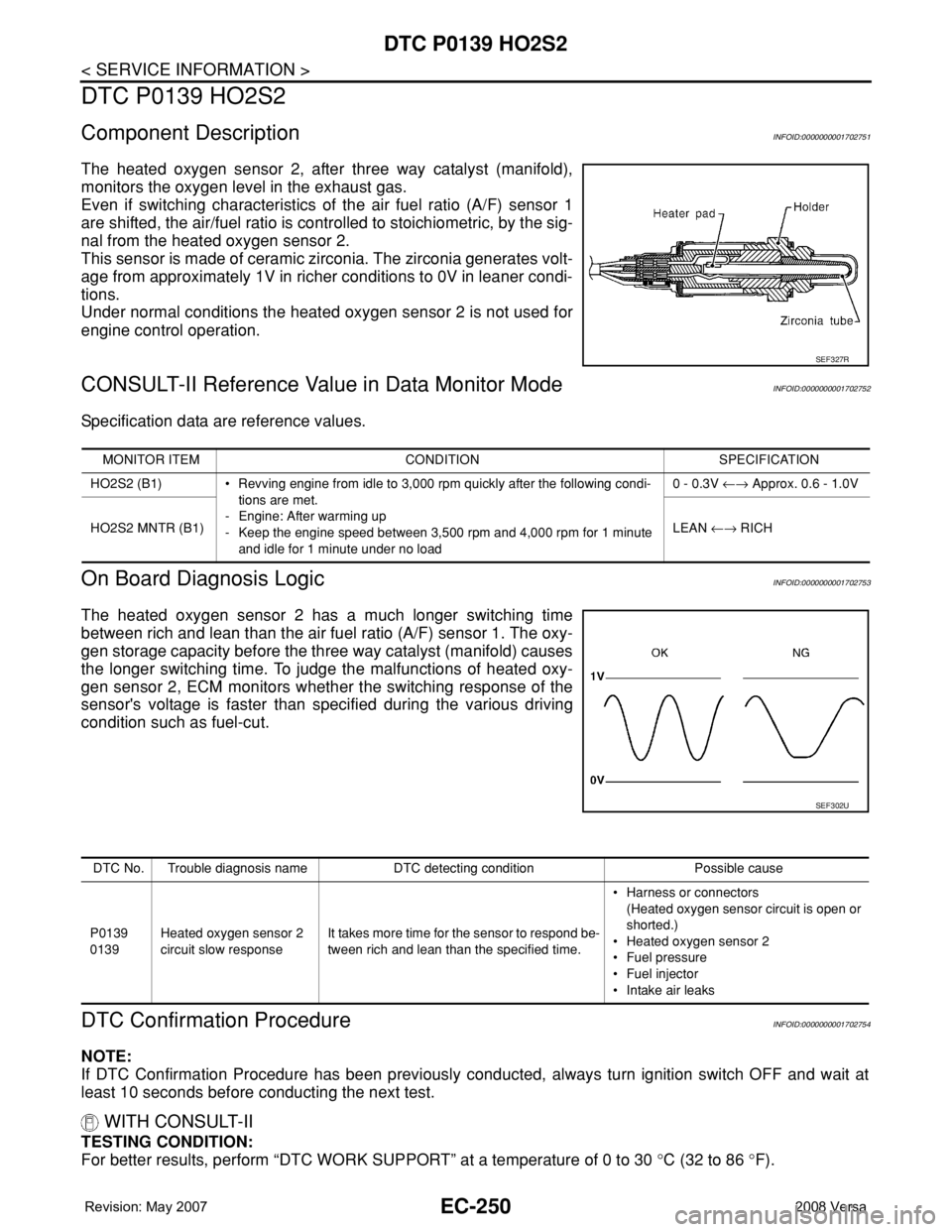
The heated oxygen sensor 2, after three way catalyst (manifold),
monitors the oxygen level in the exhaust gas.
Even if switching characteristics of the air fuel ratio (A/F) sensor 1
are shifted, the air/fuel ratio is controlled to stoichiometric, by the sig-
nal from the heated oxygen sensor 2.
This sensor is made of ceramic zirconia. The zirconia generates volt-
age from approximately 1V in richer conditions to 0V in leaner condi-
tions.
Under normal conditions the heated oxygen sensor 2 is not used for
engine control operation.
CONSULT-II Reference Value in Data Monitor ModeINFOID:0000000001702752
Specification data are reference values.
On Board Diagnosis LogicINFOID:0000000001702753
The heated oxygen sensor 2 has a much longer switching time
between rich and lean than the air fuel ratio (A/F) sensor 1. The oxy-
gen storage capacity before the three way catalyst (manifold) causes
the longer switching time. To judge the malfunctions of heated oxy-
gen sensor 2, ECM monitors whether the switching response of the
sensor's voltage is faster than specified during the various driving
condition such as fuel-cut.
DTC Confirmation ProcedureINFOID:0000000001702754
NOTE:
If DTC Confirmation Procedure has been previously conducted, always turn ignition switch OFF and wait at
least 10 seconds before conducting the next test.
WITH CONSULT-II
TESTING CONDITION:
For better results, perform “DTC WORK SUPPORT” at a temperature of 0 to 30 °C (32 to 86 °F).
SEF327R
MONITOR ITEM CONDITION SPECIFICATION
HO2S2 (B1) • Revving engine from idle to 3,000 rpm quickly after the following condi-
tions are met.
- Engine: After warming up
- Keep the engine speed between 3,500 rpm and 4,000 rpm for 1 minute
and idle for 1 minute under no load0 - 0.3V ←→ Approx. 0.6 - 1.0V
HO2S2 MNTR (B1)LEAN ←→ RICH
SEF302U
DTC No. Trouble diagnosis name DTC detecting condition Possible cause
P0139
0139Heated oxygen sensor 2
circuit slow responseIt takes more time for the sensor to respond be-
tween rich and lean than the specified time.• Harness or connectors
(Heated oxygen sensor circuit is open or
shorted.)
• Heated oxygen sensor 2
• Fuel pressure
• Fuel injector
• Intake air leaks