2008 NISSAN TIIDA ENGINE WIRING
[x] Cancel search: ENGINE WIRINGPage 869 of 2771

CVT-30
< SERVICE INFORMATION >
TROUBLE DIAGNOSIS
If an unexpected signal is sent from the solenoid to the TCM, the CVT lock-up select solenoid is turned OFF to
cancel the lock-up.
TCM Power Supply (Memory Back-up)
Transaxle assembly is protected by limiting the engine torque when the memory back-up power supply (for
controlling) from the battery is not supplied to TCM. Normal statues is restored when turning the ignition switch
OFF to ON after the normal power supply.
How to Perform Trouble Diagnosis for Quick and Accurate RepairINFOID:0000000001703453
INTRODUCTION
The TCM receives a signal from the vehicle speed sensor, PNP switch and provides shift control or lock-up
control via CVT solenoid valves.
The TCM also communicates with the ECM by means of a signal
sent from sensing elements used with the OBD-related parts of the
CVT system for malfunction-diagnostic purposes. The TCM is capa-
ble of diagnosing malfunctioning parts while the ECM can store mal-
functions in its memory.
Input and output signals must always be correct and stable in the
operation of the CVT system. The CVT system must be in good
operating condition and be free of valve seizure, solenoid valve mal-
function, etc.
It is much more difficult to diagnose an error that occurs intermit-
tently rather than continuously. Most intermittent errors are caused
by poor electric connections or improper wiring. In this case, careful
checking of suspected circuits may help prevent the replacement of
good parts.
A visual check only may not find the cause of the errors. A road test
with CONSULT-III (or GST) or a circuit tester connected should be
performed. Follow the "WORK FLOW" .
Before undertaking actual checks, take a few minutes to talk with a
customer who approaches with a driveability complaint. The cus-
tomer can supply good information about such errors, especially
intermittent ones. Find out what symptoms are present and under
what conditions they occur. A “DIAGNOSTIC WORKSHEET” as
shown on the example (Refer to "Diagnostic Worksheet Chart" )
should be used.
Start your diagnosis by looking for “conventional” errors first. This will
help troubleshoot driveability errors on an electronically controlled
engine vehicle.
Also check related Service bulletins.
WORK FLOW
A good understanding of the malfunction conditions can make troubleshooting faster and more accurate.
In general, each customer feels differently about a malfunction. It is important to fully understand the symp-
toms or conditions for a customer complaint.
Make good use of the two sheets provided, "Information From Customer" and "Diagnostic Worksheet Chart" ,
to perform the best troubleshooting possible.
Work Flow Chart
SAT631IB
SAT632I
SEF234G
Page 895 of 2771

CVT-56
< SERVICE INFORMATION >
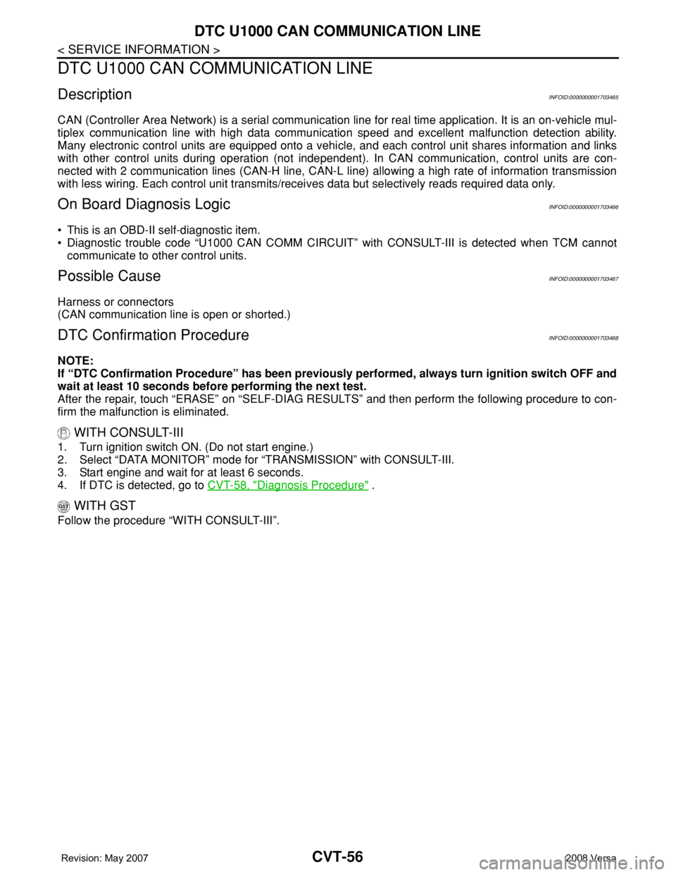
DTC U1000 CAN COMMUNICATION LINE
DTC U1000 CAN COMMUNICATION LINE
DescriptionINFOID:0000000001703465
CAN (Controller Area Network) is a serial communication line for real time application. It is an on-vehicle mul-
tiplex communication line with high data communication speed and excellent malfunction detection ability.
Many electronic control units are equipped onto a vehicle, and each control unit shares information and links
with other control units during operation (not independent). In CAN communication, control units are con-
nected with 2 communication lines (CAN-H line, CAN-L line) allowing a high rate of information transmission
with less wiring. Each control unit transmits/receives data but selectively reads required data only.
On Board Diagnosis LogicINFOID:0000000001703466
• This is an OBD-II self-diagnostic item.
• Diagnostic trouble code “U1000 CAN COMM CIRCUIT” with CONSULT-III is detected when TCM cannot
communicate to other control units.
Possible CauseINFOID:0000000001703467
Harness or connectors
(CAN communication line is open or shorted.)
DTC Confirmation ProcedureINFOID:0000000001703468
NOTE:
If “DTC Confirmation Procedure” has been previously performed, always turn ignition switch OFF and
wait at least 10 seconds before performing the next test.
After the repair, touch “ERASE” on “SELF-DIAG RESULTS” and then perform the following procedure to con-
firm the malfunction is eliminated.
WITH CONSULT-III
1. Turn ignition switch ON. (Do not start engine.)
2. Select “DATA MONITOR” mode for “TRANSMISSION” with CONSULT-III.
3. Start engine and wait for at least 6 seconds.
4. If DTC is detected, go to CVT-58, "
Diagnosis Procedure" .
WITH GST
Follow the procedure “WITH CONSULT-III”.
Page 898 of 2771

DTC U1010 TRANSMISSION CONTROL MODULE (CAN)
CVT-59
< SERVICE INFORMATION >
D
E
F
G
H
I
J
K
L
MA
B
CVT
N
O
P
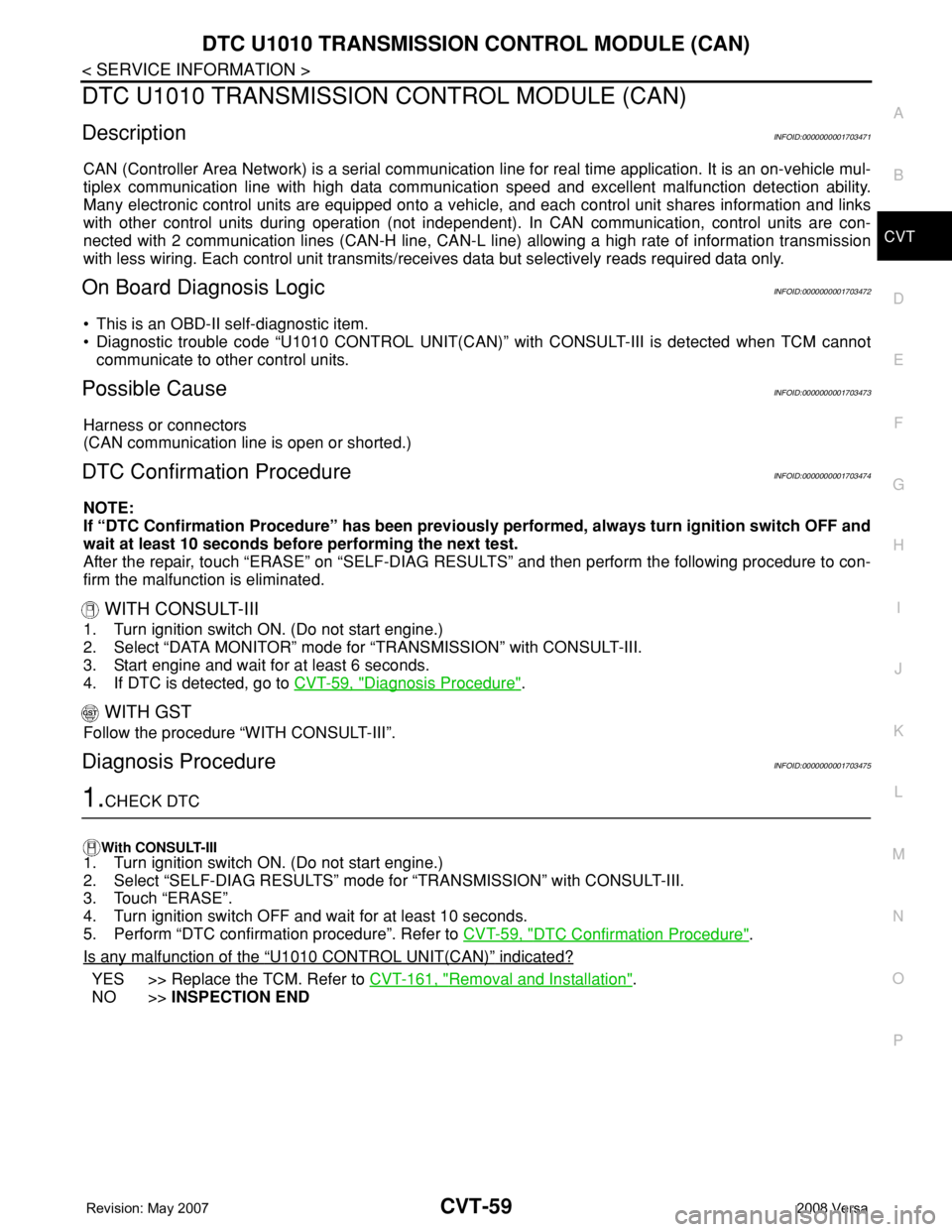
DTC U1010 TRANSMISSION CONTROL MODULE (CAN)
DescriptionINFOID:0000000001703471
CAN (Controller Area Network) is a serial communication line for real time application. It is an on-vehicle mul-
tiplex communication line with high data communication speed and excellent malfunction detection ability.
Many electronic control units are equipped onto a vehicle, and each control unit shares information and links
with other control units during operation (not independent). In CAN communication, control units are con-
nected with 2 communication lines (CAN-H line, CAN-L line) allowing a high rate of information transmission
with less wiring. Each control unit transmits/receives data but selectively reads required data only.
On Board Diagnosis LogicINFOID:0000000001703472
• This is an OBD-II self-diagnostic item.
• Diagnostic trouble code “U1010 CONTROL UNIT(CAN)” with CONSULT-III is detected when TCM cannot
communicate to other control units.
Possible CauseINFOID:0000000001703473
Harness or connectors
(CAN communication line is open or shorted.)
DTC Confirmation ProcedureINFOID:0000000001703474
NOTE:
If “DTC Confirmation Procedure” has been previously performed, always turn ignition switch OFF and
wait at least 10 seconds before performing the next test.
After the repair, touch “ERASE” on “SELF-DIAG RESULTS” and then perform the following procedure to con-
firm the malfunction is eliminated.
WITH CONSULT-III
1. Turn ignition switch ON. (Do not start engine.)
2. Select “DATA MONITOR” mode for “TRANSMISSION” with CONSULT-III.
3. Start engine and wait for at least 6 seconds.
4. If DTC is detected, go to CVT-59, "
Diagnosis Procedure".
WITH GST
Follow the procedure “WITH CONSULT-III”.
Diagnosis ProcedureINFOID:0000000001703475
1.CHECK DTC
With CONSULT-III
1. Turn ignition switch ON. (Do not start engine.)
2. Select “SELF-DIAG RESULTS” mode for “TRANSMISSION” with CONSULT-III.
3. Touch “ERASE”.
4. Turn ignition switch OFF and wait for at least 10 seconds.
5. Perform “DTC confirmation procedure”. Refer to CVT-59, "
DTC Confirmation Procedure".
Is any malfunction of the
“U1010 CONTROL UNIT(CAN)” indicated?
YES >> Replace the TCM. Refer to CVT-161, "Removal and Installation".
NO >>INSPECTION END
Page 901 of 2771

CVT-62
< SERVICE INFORMATION >
DTC P0615 START SIGNAL CIRCUIT
Diagnosis Procedure
INFOID:0000000001703482
1.CHECK STARTER RELAY SIGNAL
With CONSULT-III
1. Turn ignition switch ON. (Do not start engine.)
2. Select “SELECTION FROM MENU” in “DATA MONITOR” mode for “TRANSMISSION” with CONSULT-III
and check monitor “STRTR RLY OUT”, “STRTR RLY MON”(PNP relay) ON/OFF.
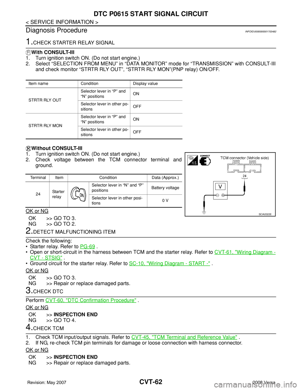
Without CONSULT-III
1. Turn ignition switch ON. (Do not start engine.)
2. Check voltage between the TCM connector terminal and
ground.
OK or NG
OK >> GO TO 3.
NG >> GO TO 2.
2.DETECT MALFUNCTIONING ITEM
Check the following:
• Starter relay. Refer to PG-69
.
• Open or short-circuit in the harness between TCM and the starter relay. Refer to CVT-61, "
Wiring Diagram -
CVT - STSIG" .
• Ground circuit for the starter relay. Refer to SC-10, "
Wiring Diagram - START -" .
OK or NG
OK >> GO TO 3.
NG >> Repair or replace damaged parts.
3.CHECK DTC
Perform CVT-60, "
DTC Confirmation Procedure" .
OK or NG
OK >>INSPECTION END
NG >> GO TO 4.
4.CHECK TCM
1. Check TCM input/output signals. Refer to CVT-45, "
TCM Terminal and Reference Value" .
2. If NG, re-check TCM pin terminals for damage or loose connection with harness connector.
OK or NG
OK >>INSPECTION END
NG >> Repair or replace damaged parts.
Item name Condition Display value
STRTR RLY OUTSelector lever in “P” and
“N” positionsON
Selector lever in other po-
sitionsOFF
STRTR RLY MONSelector lever in “P” and
“N” positionsON
Selector lever in other po-
sitionsOFF
Terminal Item Condition Data (Approx.)
24Sta r te r
relaySelector lever in “N” and “P”
positionsBattery voltage
Selector lever in other posi-
tions0 V
SCIA2022E
Page 940 of 2771

DTC P0746 PRESSURE CONTROL SOLENOID A PERFORMANCE (LINE PRES-
SURE SOLENOID VALVE)
CVT-101
< SERVICE INFORMATION >
D
E
F
G
H
I
J
K
L
MA
B
CVT
N
O
P
Without CONSULT-III
1. Start engine.
2. Check voltage between TCM connector terminal and ground.
OK or NG
OK >> GO TO 5.
NG >> GO TO 2.
2.CHECK LINE PRESSURE
Perform line pressure test. Refer to CVT-36, "
Inspections before Trouble Diagnosis".
OK or NG
OK >> GO TO 3.
NG >> Repair or replace damaged parts. Refer to CVT-36, "
Inspections before Trouble Diagnosis".
3.DETECT MALFUNCTIONING ITEM
Check pressure control solenoid valve A (line pressure solenoid valve). Refer to CVT-98, "
Component Inspec-
tion".
OK or NG
OK >> GO TO 4.
NG >> Repair or replace damaged parts.
4.CHECK OUTPUT SPEED SENSOR (SECONDARY SPEED SENSOR) SYSTEM AND INPUT SPEED
SENSOR (PRIMARY SPEED SENSOR) SYSTEM
Check output speed sensor (secondary speed sensor) system and input speed sensor (primary speed sensor)
system. Refer to CVT-80
, CVT-76.
OK or NG
OK >> GO TO 5.
NG >> Repair or replace damaged parts.
5.DETECT MALFUNCTIONING ITEM
Check the following:
• Power supply and ground circuit for TCM. Refer to CVT-122, "
Wiring Diagram - CVT - POWER".
• The TCM pin terminals for damage or loose connection with harness connector.
OK or NG
OK >> GO TO 6.
NG >> Repair or replace damaged parts.
6.CHECK DTC
Perform CVT-100, "
DTC Confirmation Procedure".
OK or NG
OK >>INSPECTION END
NG >> Replace the transaxle assembly or TCM. Refer to CVT-178, "
Removal and Installation".
Item name Condition Display value (Approx.)
PRI PRESS “N” position idle 0.4 MPa
Name Connector Terminal ConditionVoltage
(Approx.)
Transmission
fluid pressure
sensor B (Pri-
mary pressure
sensor)E32 41 - Ground “N” position idle 0.7 V
SCIA1922E
Page 1022 of 2771

DI-1
ELECTRICAL
C
D
E
F
G
H
I
J
L
M
SECTION DI
A
B
DI
N
O
P
CONTENTS
DRIVER INFORMATION SYSTEM
SERVICE INFORMATION ............................2
PRECAUTION .....................................................2
Precaution for Supplemental Restraint System
(SRS) "AIR BAG" and "SEAT BELT PRE-TEN-
SIONER" ...................................................................
2
PREPARATION ...................................................3
Commercial Service Tool ..........................................3
COMBINATION METERS ...................................4
Component Parts and Harness Connector Loca-
tion ............................................................................
4
System Description ...................................................4
Arrangement of Combination Meter ..........................6
Internal Circuit ...........................................................7
Wiring Diagram - METER - .......................................8
Combination Meter Harness Connector Terminal
Layout .....................................................................
10
Terminal and Reference Value for Combination
Meter .......................................................................
10
Self-Diagnosis Mode of Combination Meter ............11
CONSULT-III Function (METER/M&A) ...................13
Trouble Diagnosis ...................................................14
Symptom Chart .......................................................15
Power Supply and Ground Circuit Inspection .........15
Vehicle Speed Signal Inspection .............................16
Engine Speed Signal Inspection .............................17
Fuel Level Sensor Signal Inspection .......................17
Fuel Gauge Fluctuates, Indicates Wrong Value, or
Varies ......................................................................
19
Fuel Gauge Does Not Move to Full-position ...........19
DTC [U1000] CAN Communication Circuit .............19
Electrical Component Inspection .............................19
Removal and Installation .........................................20
WARNING LAMPS .............................................21
Schematic ................................................................21
Wiring Diagram - WARN - .......................................22
Oil Pressure Warning Lamp Stays Off (Ignition
Switch ON) ..............................................................
30
Oil Pressure Warning Lamp Does Not Turn Off
(Oil Pressure Is Normal) ..........................................
32
Component Inspection .............................................32
A/T INDICATOR ................................................34
System Description ..................................................34
Wiring Diagram - AT/IND - .......................................35
A/T Indicator Does Not Illuminate ............................36
CVT INDICATOR ...............................................38
System Description ..................................................38
Wiring Diagram - CVTIND - .....................................38
CVT Indicator Does Not Illuminate ..........................39
WARNING CHIME .............................................41
Component Parts and Harness Connector Loca-
tion ...........................................................................
41
System Description ..................................................41
Wiring Diagram - CHIME - .......................................44
Terminal and Reference Value for BCM ..................45
CONSULT-III Function (BCM) .................................45
Trouble Diagnosis ....................................................46
Combination Meter Buzzer Circuit Inspection .........47
Front Door Switch LH Signal Inspection ..................48
Key Switch Signal Inspection (Without Intelligent
Key) .........................................................................
49
Key Switch and Ignition Knob Switch Signal In-
spection (With Intelligent Key, When Mechanical
Key Is Used) ............................................................
50
Lighting Switch Signal Inspection ............................52
Parking Brake Switch Signal Inspection ..................52
Electrical Component Inspection .............................53
Page 1076 of 2771

EC-2
ECM Terminal and Reference Value .....................102
CONSULT-II Function (ENGINE) ..........................109
Generic Scan Tool (GST) Function .......................119
CONSULT-II Reference Value in Data Monitor
Mode ......................................................................
121
Major Sensor Reference Graph in Data Monitor
Mode ......................................................................
124
TROUBLE DIAGNOSIS - SPECIFICATION
VALUE .............................................................
127
Description .............................................................127
Testing Condition ...................................................127
Inspection Procedure .............................................127
Diagnosis Procedure .............................................127
TROUBLE DIAGNOSIS FOR INTERMITTENT
INCIDENT ........................................................
136
Description .............................................................136
Diagnosis Procedure .............................................136
POWER SUPPLY AND GROUND CIRCUIT ...137
Wiring Diagram ......................................................137
Diagnosis Procedure .............................................138
Ground Inspection .................................................142
DTC U1000, U1001 CAN COMMUNICATION
LINE .................................................................
143
Description .............................................................143
On Board Diagnosis Logic .....................................143
DTC Confirmation Procedure ................................143
Wiring Diagram ......................................................144
Diagnosis Procedure .............................................144
DTC U1010 CAN COMMUNICATION .............145
Description .............................................................145
On Board Diagnosis Logic .....................................145
DTC Confirmation Procedure ................................145
Diagnosis Procedure .............................................145
DTC P0011 IVT CONTROL .............................147
Description .............................................................147
CONSULT-II Reference Value in Data Monitor
Mode ......................................................................
147
On Board Diagnosis Logic .....................................148
DTC Confirmation Procedure ................................148
Diagnosis Procedure .............................................149
Component Inspection ...........................................150
Removal and Installation .......................................150
DTC P0031, P0032 A/F SENSOR 1 HEATER .151
Description .............................................................151
CONSULT-II Reference Value in Data Monitor
Mode ......................................................................
151
On Board Diagnosis Logic .....................................151
DTC Confirmation Procedure ................................151
Wiring Diagram ......................................................152
Diagnosis Procedure .............................................153
Component Inspection ...........................................154
Removal and Installation .......................................155
DTC P0037, P0038 HO2S2 HEATER ..............156
Description ............................................................156
CONSULT-II Reference Value in Data Monitor
Mode .....................................................................
156
On Board Diagnosis Logic ....................................156
DTC Confirmation Procedure ................................156
Wiring Diagram .....................................................158
Diagnosis Procedure .............................................159
Component Inspection ..........................................160
Removal and Installation .......................................161
DTC P0075 IVT CONTROL SOLENOID
VALVE ..............................................................
162
Component Description ........................................162
CONSULT-II Reference Value in Data Monitor
Mode .....................................................................
162
On Board Diagnosis Logic ....................................162
DTC Confirmation Procedure ................................162
Wiring Diagram .....................................................163
Diagnosis Procedure .............................................164
Component Inspection ..........................................165
Removal and Installation .......................................166
DTC P0101 MAF SENSOR ..............................167
Component Description ........................................167
CONSULT-II Reference Value in Data Monitor
Mode .....................................................................
167
On Board Diagnosis Logic ....................................167
DTC Confirmation Procedure ................................167
Overall Function Check .........................................169
Wiring Diagram .....................................................170
Diagnosis Procedure .............................................171
Component Inspection ..........................................173
Removal and Installation .......................................174
DTC P0102, P0103 MAF SENSOR ..................175
Component Description ........................................175
CONSULT-II Reference Value in Data Monitor
Mode .....................................................................
175
On Board Diagnosis Logic ....................................175
DTC Confirmation Procedure ................................175
Wiring Diagram .....................................................177
Diagnosis Procedure .............................................178
Component Inspection ..........................................180
Removal and Installation .......................................181
DTC P0112, P0113 IAT SENSOR ....................182
Component Description ........................................182
On Board Diagnosis Logic ....................................182
DTC Confirmation Procedure ................................182
Wiring Diagram .....................................................184
Diagnosis Procedure .............................................184
Component Inspection ..........................................186
Removal and Installation .......................................186
DTC P0117, P0118 ECT SENSOR ...................187
Component Description ........................................187
On Board Diagnosis Logic ....................................187
DTC Confirmation Procedure ................................188
Wiring Diagram .....................................................189
Page 1080 of 2771

EC-6
Overall Function Check .........................................406
Wiring Diagram ......................................................407
Diagnosis Procedure .............................................408
DTC P1148 CLOSED LOOP CONTROL .........411
On Board Diagnosis Logic .....................................411
DTC P1217 ENGINE OVER TEMPERATURE .412
System Description ................................................412
CONSULT-II Reference Value in Data Monitor
Mode ......................................................................
413
On Board Diagnosis Logic .....................................413
Overall Function Check .........................................413
Wiring Diagram ......................................................416
Diagnosis Procedure .............................................417
Main 13 Causes of Overheating ............................424
Component Inspection ...........................................424
DTC P1225 TP SENSOR .................................426
Component Description .........................................426
On Board Diagnosis Logic .....................................426
DTC Confirmation Procedure ................................426
Diagnosis Procedure .............................................426
Removal and Installation .......................................427
DTC P1226 TP SENSOR .................................428
Component Description .........................................428
On Board Diagnosis Logic .....................................428
DTC Confirmation Procedure ................................428
Diagnosis Procedure .............................................428
Removal and Installation .......................................429
DTC P1421 COLD START CONTROL ............430
Description .............................................................430
On Board Diagnosis Logic .....................................430
DTC Confirmation Procedure ................................430
Diagnosis Procedure .............................................430
DTC P1564 ASCD STEERING SWITCH .........432
Component Description .........................................432
CONSULT-II Reference Value in Data Monitor
Mode ......................................................................
432
On Board Diagnosis Logic .....................................432
DTC Confirmation Procedure ................................433
Wiring Diagram ......................................................434
Diagnosis Procedure .............................................435
Component Inspection ...........................................437
DTC P1572 ASCD BRAKE SWITCH ..............438
Component Description .........................................438
CONSULT-II Reference Value in Data Monitor
Mode ......................................................................
438
On Board Diagnosis Logic .....................................438
DTC Confirmation Procedure ................................439
Wiring Diagram ......................................................440
Diagnosis Procedure .............................................441
Component Inspection ...........................................445
DTC P1574 ASCD VEHICLE SPEED SEN-
SOR ..................................................................
447
Component Description .........................................447
On Board Diagnosis Logic ....................................447
DTC Confirmation Procedure ................................447
Diagnosis Procedure .............................................448
DTC P1715 INPUT SPEED SENSOR (TUR-
BINE REVOLUTION SENSOR) ........................
449
Description ............................................................449
CONSULT-II Reference Value in Data Monitor
Mode .....................................................................
449
On Board Diagnosis Logic ....................................449
Diagnosis Procedure .............................................449
DTC P1715 INPUT SPEED SENSOR (PRIMA-
RY SPEED SENSOR) .......................................
450
Description ............................................................450
CONSULT-II Reference Value in Data Monitor
Mode .....................................................................
450
On Board Diagnosis Logic ....................................450
DTC Confirmation Procedure ................................450
Diagnosis Procedure .............................................451
DTC P1805 BRAKE SWITCH ..........................452
Description ............................................................452
CONSULT-II Reference Value in Data Monitor
Mode .....................................................................
452
On Board Diagnosis Logic ....................................452
DTC Confirmation Procedure ................................452
Wiring Diagram .....................................................453
Diagnosis Procedure .............................................454
Component Inspection ..........................................455
DTC P2100, P2103 THROTTLE CONTROL
MOTOR RELAY ................................................
456
Component Description ........................................456
CONSULT-II Reference Value in Data Monitor
Mode .....................................................................
456
On Board Diagnosis Logic ....................................456
DTC Confirmation Procedure ................................456
Wiring Diagram .....................................................458
Diagnosis Procedure .............................................459
DTC P2101 ELECTRIC THROTTLE CON-
TROL FUNCTION .............................................
461
Description ............................................................461
On Board Diagnosis Logic ....................................461
DTC Confirmation Procedure ................................461
Wiring Diagram .....................................................462
Diagnosis Procedure .............................................463
Component Inspection ..........................................466
Removal and Installation .......................................466
DTC P2118 THROTTLE CONTROL MOTOR ..467
Component Description ........................................467
On Board Diagnosis Logic ....................................467
DTC Confirmation Procedure ................................467
Wiring Diagram .....................................................468
Diagnosis Procedure .............................................469
Component Inspection ..........................................470
Removal and Installation .......................................470