Page 221 of 2771
A/T SHIFT LOCK SYSTEM
AT-209
< SERVICE INFORMATION >
D
E
F
G
H
I
J
K
L
MA
B
AT
N
O
P
A/T SHIFT LOCK SYSTEM
DescriptionINFOID:0000000001703361
• The mechanical key interlock mechanism also operates as a shift lock:
With the ignition switch turned to ON, selector lever cannot be shifted from “P” position to any other position
unless brake pedal is depressed.
With the key removed, selector lever cannot be shifted from “P” position to any other position.
The key cannot be removed unless selector lever is placed in “P” position.
• The shift lock and key interlock mechanisms are controlled by the ON-OFF operation of the shift lock sole-
noid and by the operation of the rotator and slider located inside key cylinder, respectively.
Shift Lock System Parts LocationINFOID:0000000001703362
1. Key interlock cable 2. Key cylinder 3. Stop lamp switch
4. Brake pedal 5. Shift lock release button 6. Key interlock cable
7. Shift lock solenoid 8. Park position switch
BCIA0038E
Page 222 of 2771
AT-210
< SERVICE INFORMATION >
A/T SHIFT LOCK SYSTEM
Wiring Diagram - AT - SHIFT
INFOID:0000000001703363
Diagnosis ProcedureINFOID:0000000001703364
SYMPTOM 1:
•Selector lever cannot be moved from “P” position with ignition switch in ON position and brake
pedal depressed.
BCWA0666E
Page 223 of 2771

A/T SHIFT LOCK SYSTEM
AT-211
< SERVICE INFORMATION >
D
E
F
G
H
I
J
K
L
MA
B
AT
N
O
P
•Selector lever can be moved from “P” position with ignition key in ON position and brake pedal
released.
•Selector lever can be moved from “P” position when ignition switch is removed from key cylinder.
SYMPTOM 2:
•Ignition key cannot be removed when selector lever is set to “P” position.
•Ignition key can be removed when selector lever is set to any position except “P” position.
1.CHECK KEY INTERLOCK CABLE
Check key interlock cable for damage.
OK or NG
OK >> GO TO 2.
NG >> Repair key interlock cable. Refer to AT-213, "
Removal and Installation" .
2.CHECK A/T POSITION
Check A/T position. Refer to AT-207, "
Checking of A/T Position" .
OK or NG
OK >> GO TO 3.
NG >> Adjust control cable. Refer to AT-207, "
Adjustment of A/T Position" .
3.CHECK SHIFT LOCK SOLENOID AND PARK POSITION SWITCH
1. Turn ignition switch ON. (Do not start engine.)
2. Selector lever is set in “P” position.
3. Check operation sound.
OK or NG
OK >>INSPECTION END
NG >> GO TO 4.
4.CHECK POWER SOURCE
1. Turn ignition switch ON. (Do not start engine.)
2. Check voltage between A/T device harness connector terminal
5 and ground.
OK or NG
OK >> GO TO 7.
NG >> GO TO 5.
5.CHECK STOP LAMP SWITCH
1. Turn ignition switch OFF.
2. Disconnect stop lamp switch harness connector.
Condition Brake pedal Operation sound
When ignition switch is turned to ON position and selector lever is set in
“P” position.Depressed Yes
Released No
Voltage:
Brake pedal depressed: Battery voltage
Brake pedal released: 0V
SCIA7171E
Page 224 of 2771
AT-212
< SERVICE INFORMATION >
A/T SHIFT LOCK SYSTEM
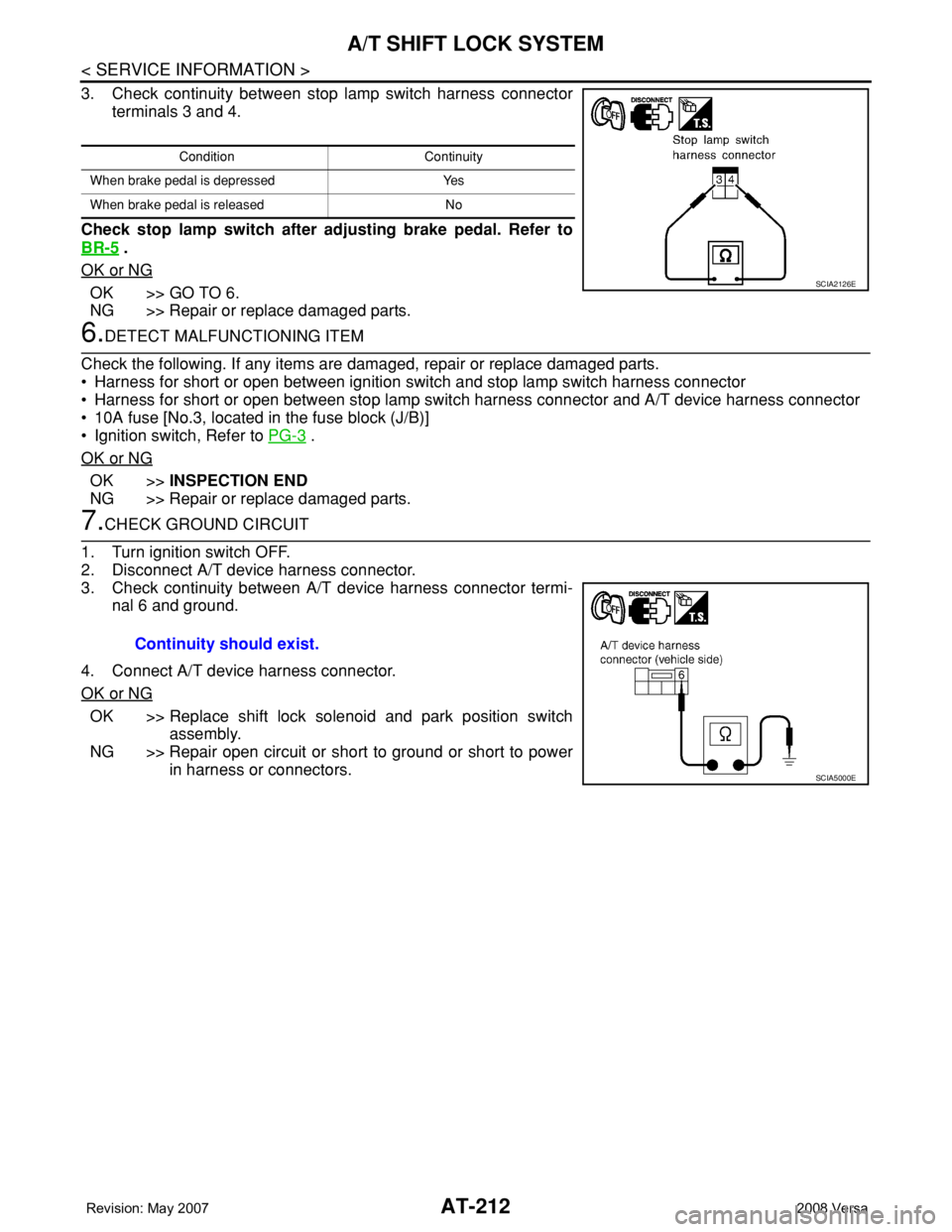
3. Check continuity between stop lamp switch harness connector
terminals 3 and 4.
Check stop lamp switch after adjusting brake pedal. Refer to
BR-5
.
OK or NG
OK >> GO TO 6.
NG >> Repair or replace damaged parts.
6.DETECT MALFUNCTIONING ITEM
Check the following. If any items are damaged, repair or replace damaged parts.
• Harness for short or open between ignition switch and stop lamp switch harness connector
• Harness for short or open between stop lamp switch harness connector and A/T device harness connector
• 10A fuse [No.3, located in the fuse block (J/B)]
• Ignition switch, Refer to PG-3
.
OK or NG
OK >>INSPECTION END
NG >> Repair or replace damaged parts.
7.CHECK GROUND CIRCUIT
1. Turn ignition switch OFF.
2. Disconnect A/T device harness connector.
3. Check continuity between A/T device harness connector termi-
nal 6 and ground.
4. Connect A/T device harness connector.
OK or NG
OK >> Replace shift lock solenoid and park position switch
assembly.
NG >> Repair open circuit or short to ground or short to power
in harness or connectors.
Condition Continuity
When brake pedal is depressed Yes
When brake pedal is released No
SCIA2126E
Continuity should exist.
SCIA5000E
Page 531 of 2771
INTELLIGENT KEY SYSTEM
BL-97
< SERVICE INFORMATION >
C
D
E
F
G
H
J
K
L
MA
B
BL
N
O
P
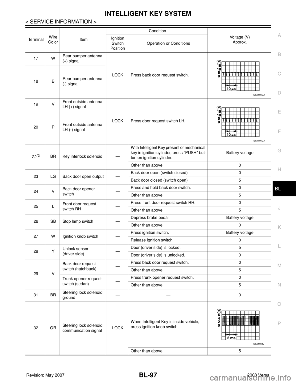
17 WRear bumper antenna
(+) signal
LOCK Press back door request switch.
18 BRear bumper antenna
(-) signal
19 VFront outside antenna
LH (+) signal
LOCK Press door request switch LH.
20 PFront outside antenna
LH (-) signal
22
*2BR Key interlock solenoid —With Intelligent Key present or mechanical
key in ignition cylinder, press "PUSH" but-
ton on ignition cylinder.Battery voltage
Other than above 0
23 LG Back door open output —Back door open (switch closed) 0
Back door closed (switch open) 5
24 VBack door opener
switch—Press and hold back door switch. 0
Other than above 5
25 LFront door request
switch RH—Press front door request switch RH. 0
Other than above 5
26 SB Stop lamp switch —Depress brake pedal Battery voltage
Other than above 0
27 W Ignition knob switch —Press ignition switch. Battery voltage
Release ignition switch. 0
28 YUnlock sensor
(driver side)—Door (driver side) is locked. 5
Door (driver side) is unlocked. 0
29 VBack door request
switch (hatchback)—Press back door request switch. 0
Other than above 5
Trunk opener request
switch (sedan)—Press trunk opener request switch. 0
Other than above 5
31 BRSteering lock solenoid
ground—— 0
32 GRSteering lock solenoid
communication signalLOCKWhen Intelligent Key is inside vehicle,
press ignition knob switch.
Other than above 5 TerminalWire
ColorItemCondition
Voltage (V)
Approx. Ignition
Switch
PositionOperation or Conditions
SIIA1910J
SIIA1910J
SIIA1911J
Page 568 of 2771
BL-134
< SERVICE INFORMATION >
INTELLIGENT KEY SYSTEM
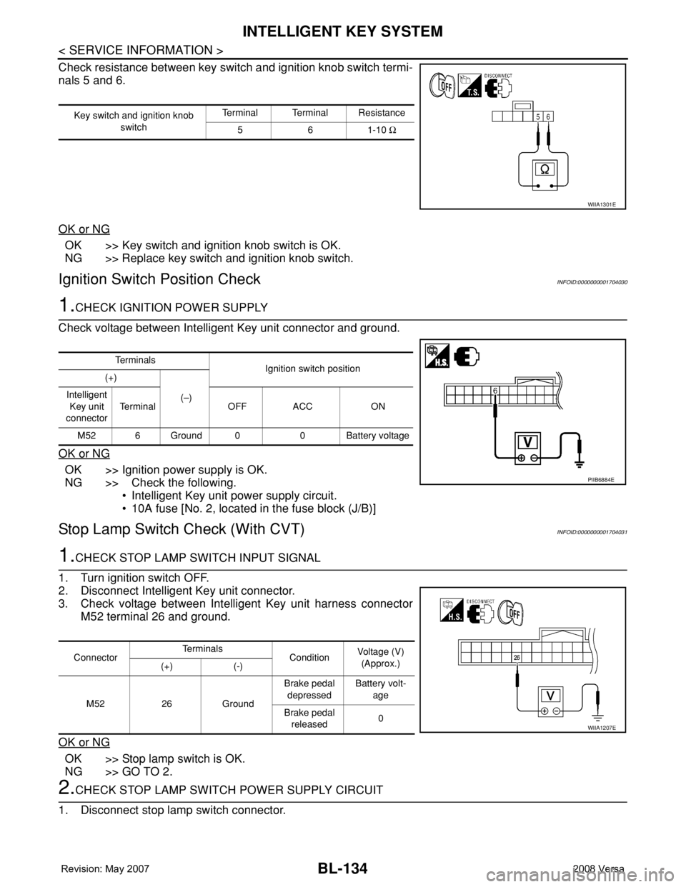
Check resistance between key switch and ignition knob switch termi-
nals 5 and 6.
OK or NG
OK >> Key switch and ignition knob switch is OK.
NG >> Replace key switch and ignition knob switch.
Ignition Switch Position CheckINFOID:0000000001704030
1.CHECK IGNITION POWER SUPPLY
Check voltage between Intelligent Key unit connector and ground.
OK or NG
OK >> Ignition power supply is OK.
NG >> Check the following.
• Intelligent Key unit power supply circuit.
• 10A fuse [No. 2, located in the fuse block (J/B)]
Stop Lamp Switch Check (With CVT)INFOID:0000000001704031
1.CHECK STOP LAMP SWITCH INPUT SIGNAL
1. Turn ignition switch OFF.
2. Disconnect Intelligent Key unit connector.
3. Check voltage between Intelligent Key unit harness connector
M52 terminal 26 and ground.
OK or NG
OK >> Stop lamp switch is OK.
NG >> GO TO 2.
2.CHECK STOP LAMP SWITCH POWER SUPPLY CIRCUIT
1. Disconnect stop lamp switch connector.
Key switch and ignition knob
switchTerminal Terminal Resistance
561-10 Ω
WIIA1301E
Te r m i n a l s
Ignition switch position
(+)
(–) Intelligent
Key unit
connectorTerminal OFF ACC ON
M52 6 Ground 0 0 Battery voltage
PIIB6884E
ConnectorTe r m i n a l s
ConditionVoltage (V)
(Approx.)
(+) (-)
M52 26 GroundBrake pedal
depressedBattery volt-
age
Brake pedal
released0
WIIA1207E
Page 569 of 2771
INTELLIGENT KEY SYSTEM
BL-135
< SERVICE INFORMATION >
C
D
E
F
G
H
J
K
L
MA
B
BL
N
O
P
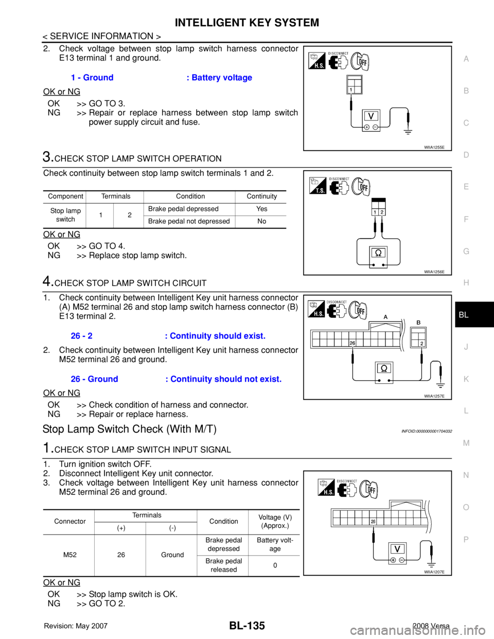
2. Check voltage between stop lamp switch harness connector
E13 terminal 1 and ground.
OK or NG
OK >> GO TO 3.
NG >> Repair or replace harness between stop lamp switch
power supply circuit and fuse.
3.CHECK STOP LAMP SWITCH OPERATION
Check continuity between stop lamp switch terminals 1 and 2.
OK or NG
OK >> GO TO 4.
NG >> Replace stop lamp switch.
4.CHECK STOP LAMP SWITCH CIRCUIT
1. Check continuity between Intelligent Key unit harness connector
(A) M52 terminal 26 and stop lamp switch harness connector (B)
E13 terminal 2.
2. Check continuity between Intelligent Key unit harness connector
M52 terminal 26 and ground.
OK or NG
OK >> Check condition of harness and connector.
NG >> Repair or replace harness.
Stop Lamp Switch Check (With M/T)INFOID:0000000001704032
1.CHECK STOP LAMP SWITCH INPUT SIGNAL
1. Turn ignition switch OFF.
2. Disconnect Intelligent Key unit connector.
3. Check voltage between Intelligent Key unit harness connector
M52 terminal 26 and ground.
OK or NG
OK >> Stop lamp switch is OK.
NG >> GO TO 2.1 - Ground : Battery voltage
WIIA1255E
Component Terminals Condition Continuity
Stop lamp
switch12Brake pedal depressed Yes
Brake pedal not depressed No
WIIA1256E
26 - 2 : Continuity should exist.
26 - Ground : Continuity should not exist.
WIIA1257E
ConnectorTe r m i n a l s
ConditionVoltage (V)
(Approx.)
(+) (-)
M52 26 GroundBrake pedal
depressedBattery volt-
age
Brake pedal
released0
WIIA1207E
Page 570 of 2771
BL-136
< SERVICE INFORMATION >
INTELLIGENT KEY SYSTEM
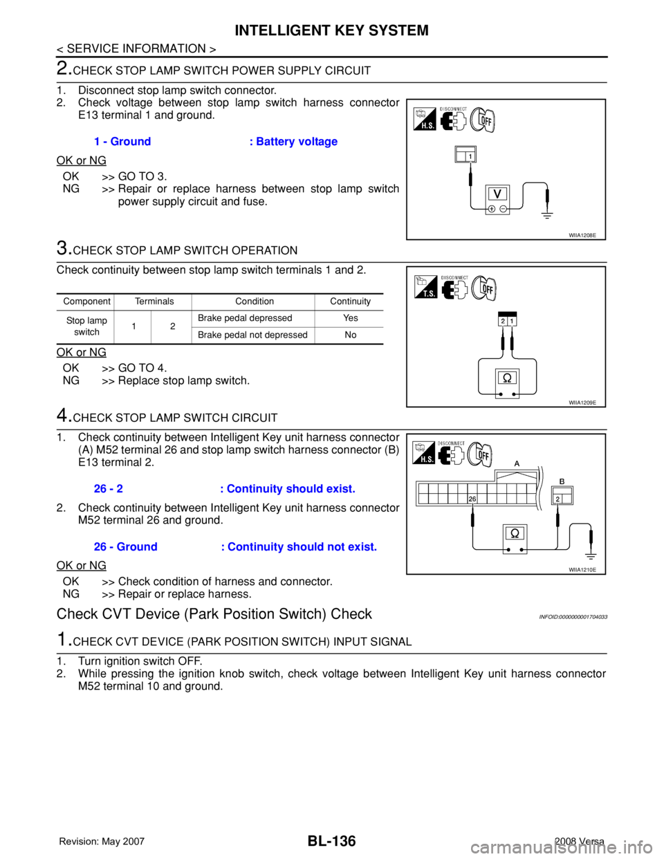
2.CHECK STOP LAMP SWITCH POWER SUPPLY CIRCUIT
1. Disconnect stop lamp switch connector.
2. Check voltage between stop lamp switch harness connector
E13 terminal 1 and ground.
OK or NG
OK >> GO TO 3.
NG >> Repair or replace harness between stop lamp switch
power supply circuit and fuse.
3.CHECK STOP LAMP SWITCH OPERATION
Check continuity between stop lamp switch terminals 1 and 2.
OK or NG
OK >> GO TO 4.
NG >> Replace stop lamp switch.
4.CHECK STOP LAMP SWITCH CIRCUIT
1. Check continuity between Intelligent Key unit harness connector
(A) M52 terminal 26 and stop lamp switch harness connector (B)
E13 terminal 2.
2. Check continuity between Intelligent Key unit harness connector
M52 terminal 26 and ground.
OK or NG
OK >> Check condition of harness and connector.
NG >> Repair or replace harness.
Check CVT Device (Park Position Switch) CheckINFOID:0000000001704033
1.CHECK CVT DEVICE (PARK POSITION SWITCH) INPUT SIGNAL
1. Turn ignition switch OFF.
2. While pressing the ignition knob switch, check voltage between Intelligent Key unit harness connector
M52 terminal 10 and ground.1 - Ground : Battery voltage
WIIA1208E
Component Terminals Condition Continuity
St op la mp
switch12Brake pedal depressed Yes
Brake pedal not depressed No
WIIA1209E
26 - 2 : Continuity should exist.
26 - Ground : Continuity should not exist.
WIIA1210E