Page 862 of 2771

CVT SYSTEM
CVT-23
< SERVICE INFORMATION >
D
E
F
G
H
I
J
K
L
MA
B
CVT
N
O
P
Optimize the line pressure and secondary pressure, depending on driving conditions, on the basis of the throt-
tle position, the engine speed, the primary pulley (input) revolution speed, the secondary pulley (output) revo-
lution speed, the brake signal, the PNP switch signal, the lock-up signal, the voltage, the target gear ratio, the
fluid temperature, and the fluid pressure.
FEEDBACK CONTROL
When controlling the normal fluid pressure or the selected fluid pressure, the secondary pressure can be set
more accurately by using the fluid pressure sensor to detect the secondary pressure and controlling the feed-
back.
Shift ControlINFOID:0000000001703443
In order to select the gear ratio which can obtain the driving force in accordance with driver's intention and the
vehicle condition, TCM monitors the driving conditions, such as the vehicle speed and the throttle position and
selects the optimum gear ratio, and determines the gear change steps to the gear ratio. Then send the com-
mand to the step motor, and control the flow-in/flow-out of line pressure from the primary pulley to determine
the position of the moving-pulley and control the gear ratio.
NOTE:
The gear ratio is set for every position separately.
“D” POSITION
Shifting over all the ranges of gear ratios from the lowest to the high-
est.
OVERDRIVE-OFF MODE
Use this position for the improved engine braking.
“L” POSITION
SCIA7958E
SCIA1953E
Page 863 of 2771

CVT-24
< SERVICE INFORMATION >
CVT SYSTEM
By limiting the gear range to the lowest position, the strong driving
force and the engine brake can be secured.
DOWNHILL ENGINE BRAKE CONTROL (AUTO ENGINE BRAKE CONTROL)
When downhill is detected with the accelerator pedal released, the engine brake will be strengthened up by
downshifting so as not to accelerate the vehicle more than necessary.
ACCELERATION CONTROL
According to vehicle speed and a change of accelerator pedal angle, driver's request for acceleration and driv-
ing scene are judged. This function assists improvement in acceleration feeling by making the engine speed
proportionate to the vehicle speed. And a shift map which can gain a larger driving force is available for com-
patibility of mileage with driveability.
Lock-up and Select ControlINFOID:0000000001703444
• The torque converter clutch piston in the torque converter is engaged to eliminate torque converter slip to
increase power transmission efficiency.
• The torque converter clutch control valve operation is controlled by the torque converter clutch solenoid
valve, which is controlled by a signal from TCM. The torque converter clutch control valve engages or
releases the torque converter clutch piston.
• When shifting between “N” (“P”) ⇔ “D” (“R”), torque converter clutch solenoid controls engagement power of
forward clutch and reverse brake.
• The lock-up applied gear range was expanded by locking up the
torque converter at a lower vehicle speed than conventional CVT
models.
TORQUE CONVERTER CLUTCH AND SELECT CONTROL VALVE CONTROL
SCIA1955E
SCIA1958E
Page 864 of 2771

CVT SYSTEM
CVT-25
< SERVICE INFORMATION >
D
E
F
G
H
I
J
K
L
MA
B
CVT
N
O
P Lock-up and Select Control System Diagram
Lock-up Released
In the lock-up released state, the torque converter clutch control valve is set into the unlocked state by the
torque converter clutch solenoid and the lock-up apply pressure is drained.
In this way, the torque converter clutch piston is not coupled.
Lock-up Applied
In the lock-up applied state, the torque converter clutch control valve is set into the locked state by the torque
converter clutch solenoid and lock-up apply pressure is generated.
In this way, the torque converter clutch piston is pressed and coupled.
Select Control
When shifting between “N” (“P”)⇔“D” (“R”), optimize the operating pressure on the basis of the throttle posi-
tion, the engine speed, and the secondary pulley (output) revolution speed to lessen the shift shock.
Control ValveINFOID:0000000001703445
FUNCTION OF CONTROL VALVE
SCIA2374E
Name Function
Torque converter regulator valve Optimizes the supply pressure for the torque converter depending on driving conditions.
Pressure regulator valve Optimizes the discharge pressure from the oil pump depending on driving conditions.
TCC control valve• Activates or deactivate the lock-up.
• Lock-up smoothly by opening lock-up operation excessively.
TCC solenoid valve Controls the TCC control valve or select control valve.
Shift control valveControls flow-in/out of line pressure from the primary pulley depending on the stroke dif-
ference between the stepping motor and the primary pulley.
Secondary valve Controls the line pressure from the secondary pulley depending on operating conditions.
Clutch regulator valve Adjusts the clutch operating pressure depending on operating conditions.
Secondary pressure solenoid valve Controls the secondary valve.
Line pressure solenoid valve Controls the line pressure control valve.
Step motor Controls the pulley ratio.
Manual valveTransmits the clutch operating pressure to each circuit in accordance with the selected
position.
Select control valve Engages forward clutch, reverse brake smoothly depending on select operation.
Select switch valveSwitches torque converter clutch solenoid valve control pressure use to torque converter
clutch control valve or select control valve.
Lock-up select solenoid valve Controls the select switch valve.
Page 873 of 2771

CVT-34
< SERVICE INFORMATION >
TROUBLE DIAGNOSIS
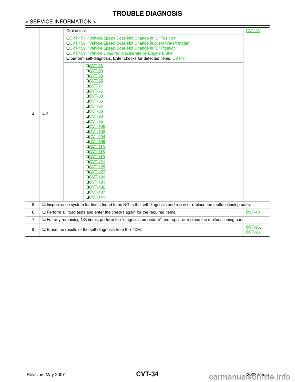
44-3.Cruise testCVT-43
❏CVT-157, "Vehicle Speed Does Not Change in "L" Position"
❏CVT-158, "Vehicle Speed Does Not Change in overdrive-off mode"
❏CVT-159, "Vehicle Speed Does Not Change in "D" Position"
❏CVT-159, "Vehicle Does Not Decelerate by Engine Brake"
❏ perform self-diagnosis. Enter checks for detected items. CVT-47
❏CVT-56
❏CVT-60
❏CVT-63
❏CVT-65
❏CVT-71
❏CVT-76
❏CVT-80
❏CVT-85
❏CVT-87
❏CVT-88
❏CVT-93
❏CVT-95
❏CVT-100
❏CVT-102
❏CVT-104
❏CVT-109
❏CVT-113
❏CVT-115
❏CVT-119
❏CVT-121
❏CVT-125
❏CVT-127
❏CVT-129
❏CVT-131
❏CVT-132
❏CVT-137
❏CVT-141
5❏ Inspect each system for items found to be NG in the self-diagnosis and repair or replace the malfunctioning parts.
6❏ Perform all road tests and enter the checks again for the required items.CVT-40
7❏ For any remaining NG items, perform the “diagnosis procedure” and repair or replace the malfunctioning parts.
8❏ Erase the results of the self-diagnosis from the TCM.CVT-26
,
CVT-26
Page 998 of 2771

TROUBLE DIAGNOSIS FOR SYMPTOMS
CVT-159
< SERVICE INFORMATION >
D
E
F
G
H
I
J
K
L
MA
B
CVT
N
O
P
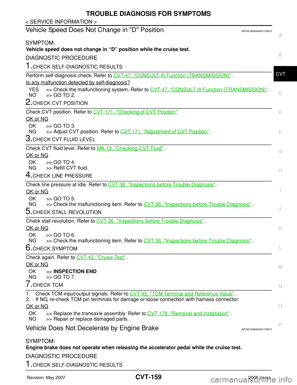
Vehicle Speed Does Not Change in "D" PositionINFOID:0000000001703672
SYMPTOM:
Vehicle speed does not change in “D” position while the cruise test.
DIAGNOSTIC PROCEDURE
1.CHECK SELF-DIAGNOSTIC RESULTS
Perform self-diagnosis check. Refer to CVT-47, "
CONSULT-III Function (TRANSMISSION)" .
Is any malfunction detected by self-diagnosis?
YES >> Check the malfunctioning system. Refer to CVT-47, "CONSULT-III Function (TRANSMISSION)" .
NO >> GO TO 2.
2.CHECK CVT POSITION
Check CVT position. Refer to CVT-171, "
Checking of CVT Position"
OK or NG
OK >> GO TO 3.
NG >> Adjust CVT position. Refer to CVT-171, "
Adjustment of CVT Position" .
3.CHECK CVT FLUID LEVEL
Check CVT fluid level. Refer to MA-19, "
Checking CVT Fluid" .
OK or NG
OK >> GO TO 4.
NG >> Refill CVT fluid.
4.CHECK LINE PRESSURE
Check line pressure at idle. Refer to CVT-36, "
Inspections before Trouble Diagnosis" .
OK or NG
OK >> GO TO 5.
NG >> Check the malfunctioning item. Refer to CVT-36, "
Inspections before Trouble Diagnosis" .
5.CHECK STALL REVOLUTION
Check stall revolution. Refer to CVT-36, "
Inspections before Trouble Diagnosis" .
OK or NG
OK >> GO TO 6.
NG >> Check the malfunctioning item. Refer to CVT-36, "
Inspections before Trouble Diagnosis" .
6.CHECK SYMPTOM
Check again. Refer to CVT-43, "
Cruise Test" .
OK or NG
OK >>INSPECTION END
NG >> GO TO 7.
7.CHECK TCM
1. Check TCM input/output signals. Refer to CVT-45, "
TCM Terminal and Reference Value" .
2. If NG, re-check TCM pin terminals for damage or loose connection with harness connector.
OK or NG
OK >> Replace the transaxle assembly. Refer to CVT-178, "Removal and Installation" .
NG >> Repair or replace damaged parts.
Vehicle Does Not Decelerate by Engine BrakeINFOID:0000000001703673
SYMPTOM:
Engine brake does not operate when releasing the accelerator pedal while the cruise test.
DIAGNOSTIC PROCEDURE
1.CHECK SELF-DIAGNOSTIC RESULTS
Page 1001 of 2771
CVT-162
< SERVICE INFORMATION >
CVT SHIFT LOCK SYSTEM
CVT SHIFT LOCK SYSTEM
DescriptionINFOID:0000000001703675
• The mechanical key interlock mechanism also operates as a shift lock:
With the ignition switch turned to ON, selector lever cannot be shifted from “P” position to any other position
unless brake pedal is depressed.
With the key removed, selector lever cannot be shifted from “P” position to any other position.
The key cannot be removed unless selector lever is placed in “P” position.
• The shift lock and key interlock mechanisms are controlled by the ON-OFF operation of the shift lock sole-
noid and by the operation of the rotator and slider located inside key cylinder, respectively.
Shift Lock System Electrical Parts LocationINFOID:0000000001703676
1. Key interlock cable 2. Key cylinder 3. Stop lamp switch
4. Brake pedal 5. Shift lock release button 6. Key interlock cable
7. Shift lock solenoid 8. Park position switch
BCIA0034E
Page 1002 of 2771
CVT SHIFT LOCK SYSTEM
CVT-163
< SERVICE INFORMATION >
D
E
F
G
H
I
J
K
L
MA
B
CVT
N
O
P
Wiring Diagram - CVT - SHIFTINFOID:0000000001703677
Diagnosis ProcedureINFOID:0000000001703678
SYMPTOM 1:
•Selector lever cannot be moved from “P” position with ignition switch in ON position and brake
pedal depressed.
BCWA0685E
Page 1003 of 2771

CVT-164
< SERVICE INFORMATION >
CVT SHIFT LOCK SYSTEM
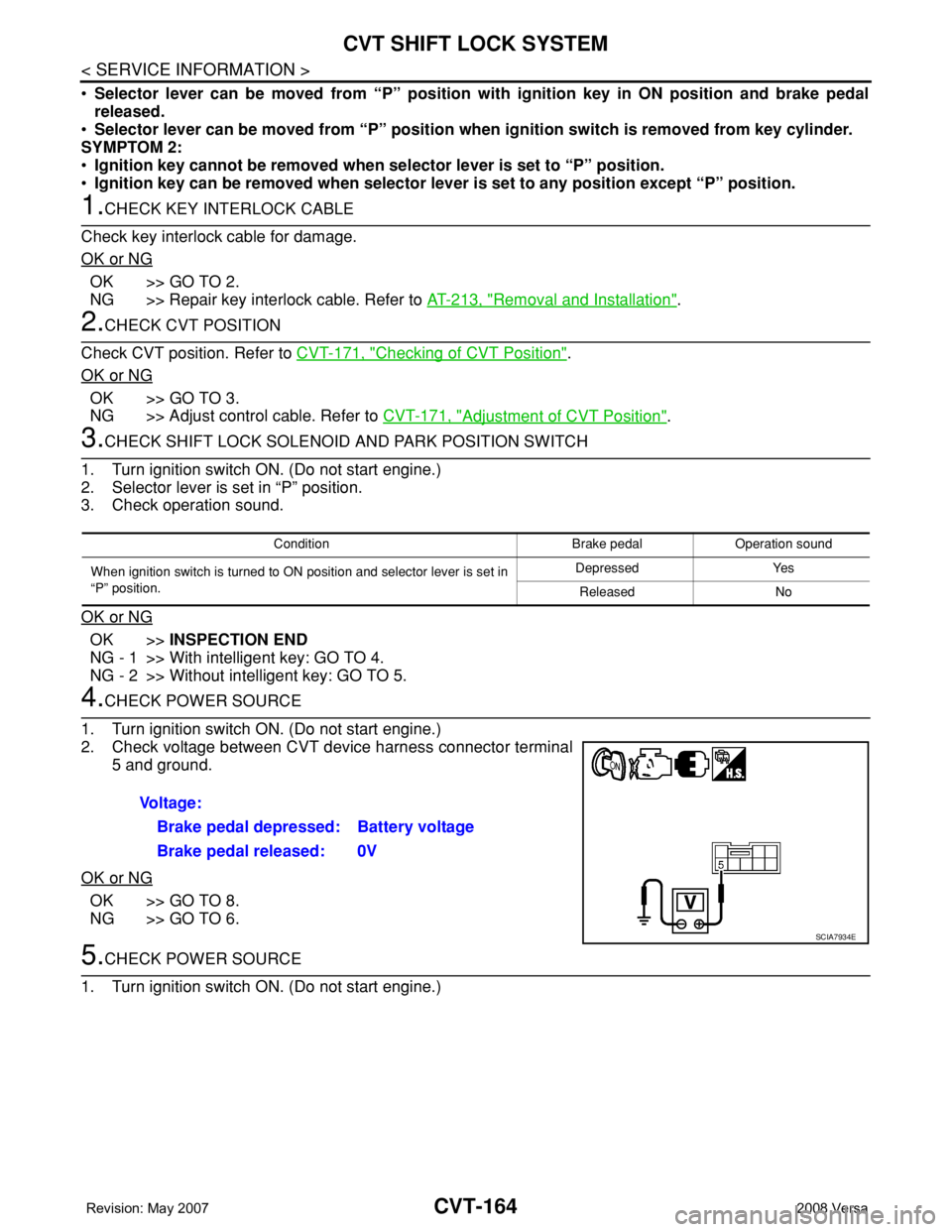
•Selector lever can be moved from “P” position with ignition key in ON position and brake pedal
released.
•Selector lever can be moved from “P” position when ignition switch is removed from key cylinder.
SYMPTOM 2:
•Ignition key cannot be removed when selector lever is set to “P” position.
•Ignition key can be removed when selector lever is set to any position except “P” position.
1.CHECK KEY INTERLOCK CABLE
Check key interlock cable for damage.
OK or NG
OK >> GO TO 2.
NG >> Repair key interlock cable. Refer to AT-213, "
Removal and Installation".
2.CHECK CVT POSITION
Check CVT position. Refer to CVT-171, "
Checking of CVT Position".
OK or NG
OK >> GO TO 3.
NG >> Adjust control cable. Refer to CVT-171, "
Adjustment of CVT Position".
3.CHECK SHIFT LOCK SOLENOID AND PARK POSITION SWITCH
1. Turn ignition switch ON. (Do not start engine.)
2. Selector lever is set in “P” position.
3. Check operation sound.
OK or NG
OK >>INSPECTION END
NG - 1 >> With intelligent key: GO TO 4.
NG - 2 >> Without intelligent key: GO TO 5.
4.CHECK POWER SOURCE
1. Turn ignition switch ON. (Do not start engine.)
2. Check voltage between CVT device harness connector terminal
5 and ground.
OK or NG
OK >> GO TO 8.
NG >> GO TO 6.
5.CHECK POWER SOURCE
1. Turn ignition switch ON. (Do not start engine.)
Condition Brake pedal Operation sound
When ignition switch is turned to ON position and selector lever is set in
“P” position.Depressed Yes
Released No
Voltage:
Brake pedal depressed: Battery voltage
Brake pedal released: 0V
SCIA7934E