Page 2199 of 2771
LT-62
< SERVICE INFORMATION >
COMBINATION SWITCH
COMBINATION SWITCH
Wiring Diagram - COMBSW -INFOID:0000000001704432
Combination Switch Reading FunctionINFOID:0000000001704433
For details, refer to BCS-3, "System Description" .
LKWA0333E
Page 2203 of 2771
LT-66
< SERVICE INFORMATION >
STOP LAMP
STOP LAMP
Wiring Diagram - STOP/LINFOID:0000000001704438
HATCHBACK
WKWA5833E
Page 2204 of 2771
STOP LAMP
LT-67
< SERVICE INFORMATION >
C
D
E
F
G
H
I
J
L
MA
B
LT
N
O
P
Wiring Diagram - STOP/LINFOID:0000000001704439
SEDAN
Bulb Replacement for High-Mounted Stop LampINFOID:0000000001704440
HATCHBACK
The LED element is not serviced separately, the high-mounted stop lamp must be replaced as an assembly.
Refer to LT-68, "
Removal and Installation of High-Mounted Stop Lamp".
ALLWA0128GB
Page 2207 of 2771
LT-70
< SERVICE INFORMATION >
BACK-UP LAMP
BACK-UP LAMP
Wiring Diagram - BACK/L -INFOID:0000000001704444
Bulb ReplacementINFOID:0000000001704445
Refer to LT-85, "Bulb Replacement" .
WKWA5810E
Page 2212 of 2771
PARKING, LICENSE PLATE AND TAIL LAMPS
LT-75
< SERVICE INFORMATION >
C
D
E
F
G
H
I
J
L
MA
B
LT
N
O
P
Wiring Diagram - TAIL/L -INFOID:0000000001704451
LKWA0336E
Page 2231 of 2771
LT-94
< SERVICE INFORMATION >
INTERIOR ROOM LAMP
Wiring Diagram - INT/L -
INFOID:0000000001704471
WKWA5813E
Page 2245 of 2771
LT-108
< SERVICE INFORMATION >
ILLUMINATION
Wiring Diagram - ILL -
INFOID:0000000001704483
LKWA0344E
Page 2252 of 2771

LU-2
< SERVICE INFORMATION >
PRECAUTIONS
SERVICE INFORMATION
PRECAUTIONS
Precaution for Supplemental Restraint System (SRS) "AIR BAG" and "SEAT BELT
PRE-TENSIONER"
INFOID:0000000001790697
The Supplemental Restraint System such as “AIR BAG” and “SEAT BELT PRE-TENSIONER”, used along
with a front seat belt, helps to reduce the risk or severity of injury to the driver and front passenger for certain
types of collision. This system includes seat belt switch inputs and dual stage front air bag modules. The SRS
system uses the seat belt switches to determine the front air bag deployment, and may only deploy one front
air bag, depending on the severity of a collision and whether the front occupants are belted or unbelted.
Information necessary to service the system safely is included in the SRS and SB section of this Service Man-
ual.
WARNING:
• To avoid rendering the SRS inoperative, which could increase the risk of personal injury or death in
the event of a collision which would result in air bag inflation, all maintenance must be performed by
an authorized NISSAN/INFINITI dealer.
• Improper maintenance, including incorrect removal and installation of the SRS, can lead to personal
injury caused by unintentional activation of the system. For removal of Spiral Cable and Air Bag
Module, see the SRS section.
• Do not use electrical test equipment on any circuit related to the SRS unless instructed to in this
Service Manual. SRS wiring harnesses can be identified by yellow and/or orange harnesses or har-
ness connectors.
Precaution for Liquid GasketINFOID:0000000001702514
LIQUID GASKET APPLICATION PROCEDURE
1. Remove old liquid gasket adhering to the liquid gasket application surface and the mating surface.
• Remove liquid gasket completely from the liquid gasket application surface, bolts, and bolt holes.
2. Wipe the liquid gasket application surface and the mating surface with white gasoline (lighting and heating
use) to remove adhering moisture, grease and foreign materials.
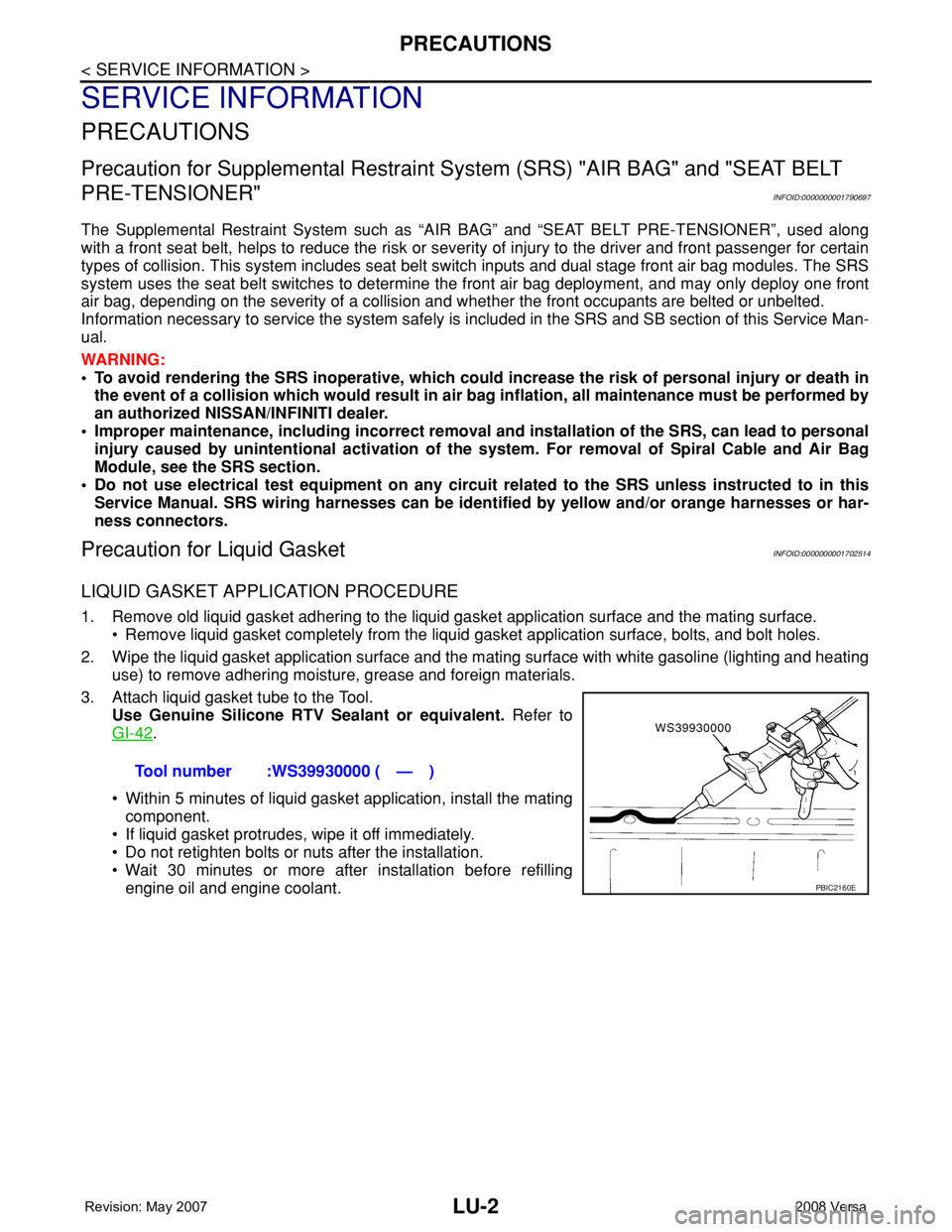
3. Attach liquid gasket tube to the Tool.
Use Genuine Silicone RTV Sealant or equivalent. Refer to
GI-42
.
• Within 5 minutes of liquid gasket application, install the mating
component.
• If liquid gasket protrudes, wipe it off immediately.
• Do not retighten bolts or nuts after the installation.
• Wait 30 minutes or more after installation before refilling
engine oil and engine coolant.Tool number :WS39930000 ( — )
PBIC2160E