2008 NISSAN TIIDA replace battery
[x] Cancel search: replace batteryPage 2170 of 2771
HEADLAMP (FOR CANADA) - DAYTIME LIGHT SYSTEM -
LT-33
< SERVICE INFORMATION >
C
D
E
F
G
H
I
J
L
MA
B
LT
N
O
P
How to Perform Trouble DiagnosisINFOID:0000000001704388
1. Confirm the symptom or customer complaint.
2. Understand operation, description and function description. Refer to LT-25, "
System Description" .
3. Perform the Preliminary Check. Refer to LT-33, "
Preliminary Check" .
4. Check symptom and repair or replace the cause of the malfunction.
5. Does the daytime light system operate normally? If YES, GO TO 6. If NO, GO TO 4.
6. INSPECTION END
Preliminary CheckINFOID:0000000001704389
CHECK BCM CONFIGURATION
1.CHECK BCM CONFIGURATION
Confirm BCM configuration for "DTRL" is set to "WITH". Refer to BCS-17, "
Configuration" .
OK or NG
OK >> Continue preliminary check. Refer to BCS-15, "BCM Power Supply and Ground Circuit Inspec-
tion" .
NG >> Change BCM configuration for "DTRL" to "WITH". Refer to BCS-17, "
Configuration" .
CHECK POWER SUPPLY AND GROUND CIRCUIT FOR BCM
Refer to BCS-15, "BCM Power Supply and Ground Circuit Inspection" .
CHECK POWER SUPPLY AND GROUND CIRCUIT FOR IPDM E/R
Refer to PG-25, "IPDM E/R Power/Ground Circuit Inspection" .
CONSULT-III Function (BCM)INFOID:0000000001704390
Refer to LT- 11 , "CONSULT-III Function (BCM)" .
CONSULT-III Function (IPDM E/R)INFOID:0000000001704391
Refer to LT-12, "CONSULT-III Function (IPDM E/R)" .
Daytime Light Control Does Not Operate Properly (High Beam Headlamps Operate
Properly)
INFOID:0000000001704392
1.CHECK DAYTIME LIGHT RELAY 1 FUSE
Inspect daytime light relay fuse 10A fuse (No. 26, located in the fuse and fusible link box).
OK or NG
OK >> GO TO 2.
NG >> Repair harness.
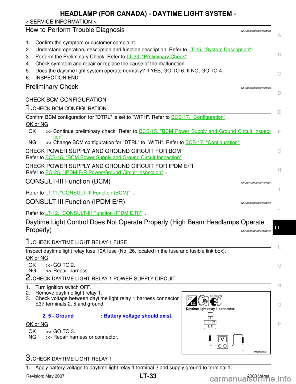
2.CHECK DAYTIME LIGHT RELAY 1 POWER SUPPLY CIRCUIT
1. Turn ignition switch OFF.
2. Remove daytime light relay 1.
3. Check voltage between daytime light relay 1 harness connector
E37 terminals 2, 5 and ground.
OK or NG
OK >> GO TO 3.
NG >> Repair harness or connector.
3.CHECK DAYTIME LIGHT RELAY 1
1. Apply battery voltage to daytime light relay 1 terminal 2 and supply ground to terminal 1.2, 5 - Ground : Battery voltage should exist.
WKIA3305E
Page 2181 of 2771
LT-44
< SERVICE INFORMATION >
FRONT FOG LAMP
1. Start auto active test. Refer to PG-19, "Auto Active Test" .
2. Make sure front fog lamp operates.
OK or NG
OK >> GO TO 4.
NG >> GO TO 5.
4.CHECK IPDM E/R
1. Select “IPDM E/R” on CONSULT-III. Select “DATA MONITOR” on “SELECT DIAG MODE” screen.
2. Make sure “FR FOG REQ” turns ON when front fog lamp switch is in ON position.
OK or NG
OK >> Replace IPDM E/R. Refer to PG-26, "Removal and Installation of IPDM E/R" .
NG >> Replace BCM. Refer toBCS-18, "
Removal and Installation of BCM" .
5.CHECK FOG LAMP INPUT SIGNAL
With CONSULT-III
1. Turn ignition switch OFF.
2. Disconnect front fog lamp connector.
3. Select “IPDM E/R” on CONSULT-III, and select “ACTIVE TEST” on “SELECT DIAG MODE” screen.
4. Select “EXTERNAL LAMPS” on “SELECT TEST ITEM” screen.
5. Touch “FOG” screen.
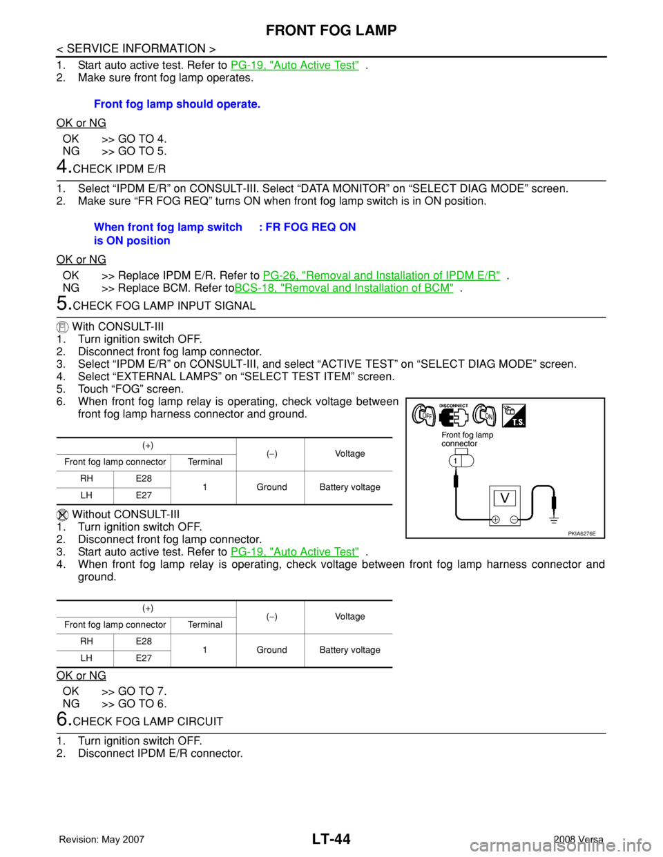
6. When front fog lamp relay is operating, check voltage between
front fog lamp harness connector and ground.
Without CONSULT-III
1. Turn ignition switch OFF.
2. Disconnect front fog lamp connector.
3. Start auto active test. Refer to PG-19, "
Auto Active Test" .
4. When front fog lamp relay is operating, check voltage between front fog lamp harness connector and
ground.
OK or NG
OK >> GO TO 7.
NG >> GO TO 6.
6.CHECK FOG LAMP CIRCUIT
1. Turn ignition switch OFF.
2. Disconnect IPDM E/R connector.Front fog lamp should operate.
When front fog lamp switch
is ON position: FR FOG REQ ON
(+)
(−) Voltage
Front fog lamp connector Terminal
RH E28
1 Ground Battery voltage
LH E27
(+)
(−) Voltage
Front fog lamp connector Terminal
RH E28
1 Ground Battery voltage
LH E27
PKIA6276E
Page 2195 of 2771
LT-58
< SERVICE INFORMATION >
TURN SIGNAL AND HAZARD WARNING LAMPS
Hazard Warning Lamp Does Not Operate But Turn Signal Lamp Operates
INFOID:0000000001704424
1.CHECK HAZARD SWITCH INPUT SIGNAL
With CONSULT-III
1. Select “BCM” on CONSULT-III. Select “FLASHER” on “SELECT TEST ITEM” screen.
2. Select “DATA MONITOR” on “SELECT DIAG MODE” screen. Make sure that “HAZARD SW” turns ON-
OFF linked with operation of hazard switch.
Without CONSULT-III
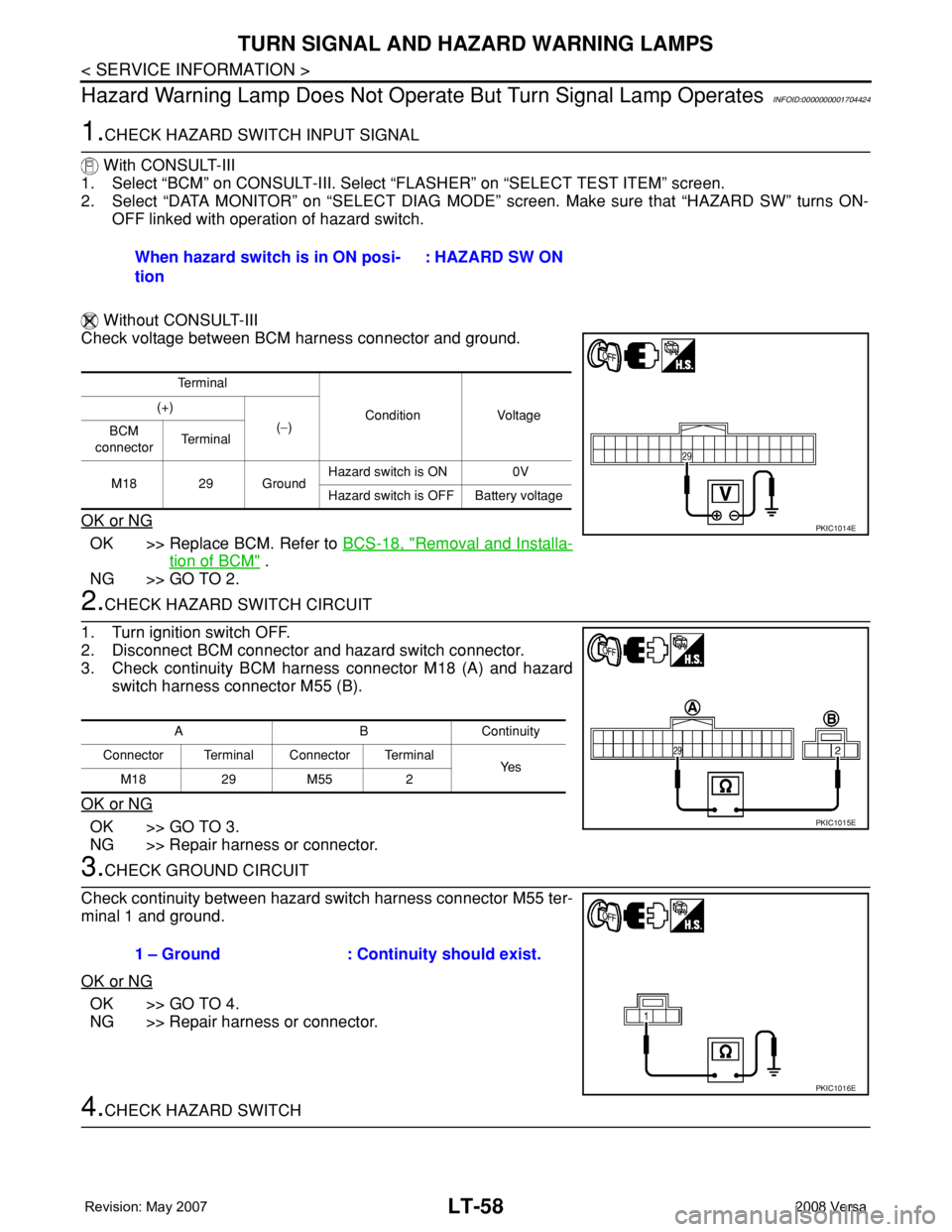
Check voltage between BCM harness connector and ground.
OK or NG
OK >> Replace BCM. Refer to BCS-18, "Removal and Installa-
tion of BCM" .
NG >> GO TO 2.
2.CHECK HAZARD SWITCH CIRCUIT
1. Turn ignition switch OFF.
2. Disconnect BCM connector and hazard switch connector.
3. Check continuity BCM harness connector M18 (A) and hazard
switch harness connector M55 (B).
OK or NG
OK >> GO TO 3.
NG >> Repair harness or connector.
3.CHECK GROUND CIRCUIT
Check continuity between hazard switch harness connector M55 ter-
minal 1 and ground.
OK or NG
OK >> GO TO 4.
NG >> Repair harness or connector.
4.CHECK HAZARD SWITCHWhen hazard switch is in ON posi-
tion : HAZARD SW ON
Te r m i n a l
Condition Voltage (+)
(−)
BCM
connectorTe r m i n a l
M18 29 GroundHazard switch is ON 0V
Hazard switch is OFF Battery voltage
PKIC1014E
ABContinuity
Connector Terminal Connector Terminal
Ye s
M18 29 M55 2
PKIC1015E
1 – Ground : Continuity should exist.
PKIC1016E
Page 2217 of 2771
LT-80
< SERVICE INFORMATION >
PARKING, LICENSE PLATE AND TAIL LAMPS
1. Start auto active test. Refer to PG-19, "Auto Active Test" .
2. Make sure parking, license plate and tail lamps operate.
OK or NG
OK >> GO TO 4.
NG >> GO TO 5.
4.CHECK IPDM E/R
1. Select “IPDM E/R” on CONSULT-III, and select “DATA MONITOR” on “SELECT DIAG MODE” screen.
2. Make sure “TAIL&CLR REQ” turns ON when lighting switch is in 1ST position.
OK or NG
OK >> Replace IPDM E/R. Refer to PG-26, "Removal and Installation of IPDM E/R" .
NG >> Replace BCM. Refer to BCS-18, "
Removal and Installation of BCM" .
5.CHECK INPUT SIGNAL
With CONSULT-III
1. Turn ignition switch OFF.
2. Disconnect front combination lamp, license plate lamp and rear combination lamp connectors.
3. Select “IPDM E/R” on CONSULT-III, and select “ACTIVE TEST” on “SELECT DIAG MODE” screen.
4. Select “EXTERNAL LAMPS” on “SELECT TEST ITEM” screen.
5. Touch “TAIL” on "ACTIVE TEST" screen.
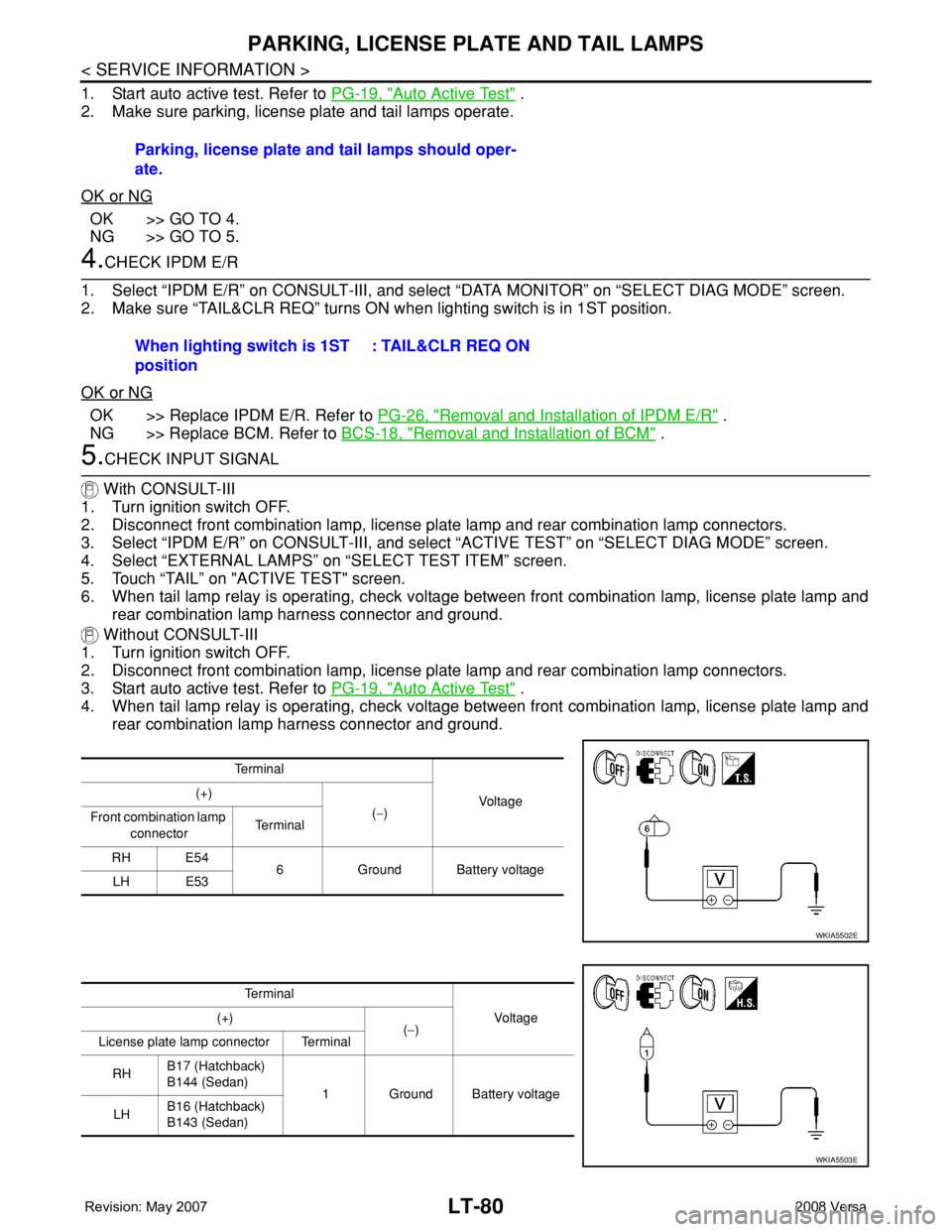
6. When tail lamp relay is operating, check voltage between front combination lamp, license plate lamp and
rear combination lamp harness connector and ground.
Without CONSULT-III
1. Turn ignition switch OFF.
2. Disconnect front combination lamp, license plate lamp and rear combination lamp connectors.
3. Start auto active test. Refer to PG-19, "
Auto Active Test" .
4. When tail lamp relay is operating, check voltage between front combination lamp, license plate lamp and
rear combination lamp harness connector and ground.Parking, license plate and tail lamps should oper-
ate.
When lighting switch is 1ST
position: TAIL&CLR REQ ON
Te r m i n a l
Voltag e (+)
(−)
Front combination lamp
connectorTe r m i n a l
RH E54
6 Ground Battery voltage
LH E53
WKIA5502E
Te r m i n a l
Vo l ta g e (+)
(−)
License plate lamp connector Terminal
RHB17 (Hatchback)
B144 (Sedan)
1 Ground Battery voltage
LHB16 (Hatchback)
B143 (Sedan)
WKIA5503E
Page 2218 of 2771
PARKING, LICENSE PLATE AND TAIL LAMPS
LT-81
< SERVICE INFORMATION >
C
D
E
F
G
H
I
J
L
MA
B
LT
N
O
P
OK or NG
OK >> GO TO 7.
NG >> GO TO 6.
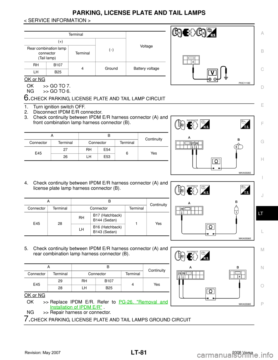
6.CHECK PARKING, LICENSE PLATE AND TAIL LAMP CIRCUIT
1. Turn ignition switch OFF.
2. Disconnect IPDM E/R connector.
3. Check continuity between IPDM E/R harness connector (A) and
front combination lamp harness connector (B).
4. Check continuity between IPDM E/R harness connector (A) and
license plate lamp harness connector (B).
5. Check continuity between IPDM E/R harness connector (A) and
rear combination lamp harness connector (B).
OK or NG
OK >> Replace IPDM E/R. Refer to PG-26, "Removal and
Installation of IPDM E/R" .
NG >> Repair harness or connector.
7.CHECK PARKING, LICENSE PLATE AND TAIL LAMPS GROUND CIRCUIT
Te r m i n a l
Vo l ta g e (+)
(−) Rear combination lamp
connector
(Tail lamp)Te r m i n a l
RH B107
4 Ground Battery voltage
LH B25
P K I C 111 8 E
AB
Continuity
Connector Terminal Connector Terminal
E4527 RH E54
6Yes
26 LH E53
WKIA5505E
AB
Continuity
Connector Terminal Connector Terminal
E45 28RHB17 (Hatchback)
B144 (Sedan)
1Yes
LHB16 (Hatchback)
B143 (Sedan)
WKIA5506E
AB
Continuity
Connector Terminal Connector Terminal
E4529 RH B107
4Yes
28 LH B25
WKIA5508E
Page 2237 of 2771
LT-100
< SERVICE INFORMATION >
INTERIOR ROOM LAMP
NOTE:
Vehicles without intelligent key system display this item, but cannot be monitored.
ACTIVE TEST
Display Item List
WORK SUPPORT
Display Item List
Interior Room Lamp Control Does Not Operate (With Map Lamp)INFOID:0000000001704476
1.CHECK EACH SWITCH
Select "BCM" on CONSULT-III. With "INT LAMP" data monitor, make sure switches listed in display item list
turn ON-OFF linked with switch operation. Refer to LT-99, "
CONSULT-III Function (BCM)" for switches and
their functions.
OK or NG
OK >> GO TO 2.
NG >> Inspect malfunctioning switch system.
2.ACTIVE TEST
1. Select “BCM” on CONSULT-III. Select “INT LAMP" active test.
2. When room lamp switch is in DOOR position, make sure room lamp operates.
OK or NG
OK >> Replace BCM. Refer to BCS-18, "Removal and Installation of BCM" .
NG >> GO TO 3.
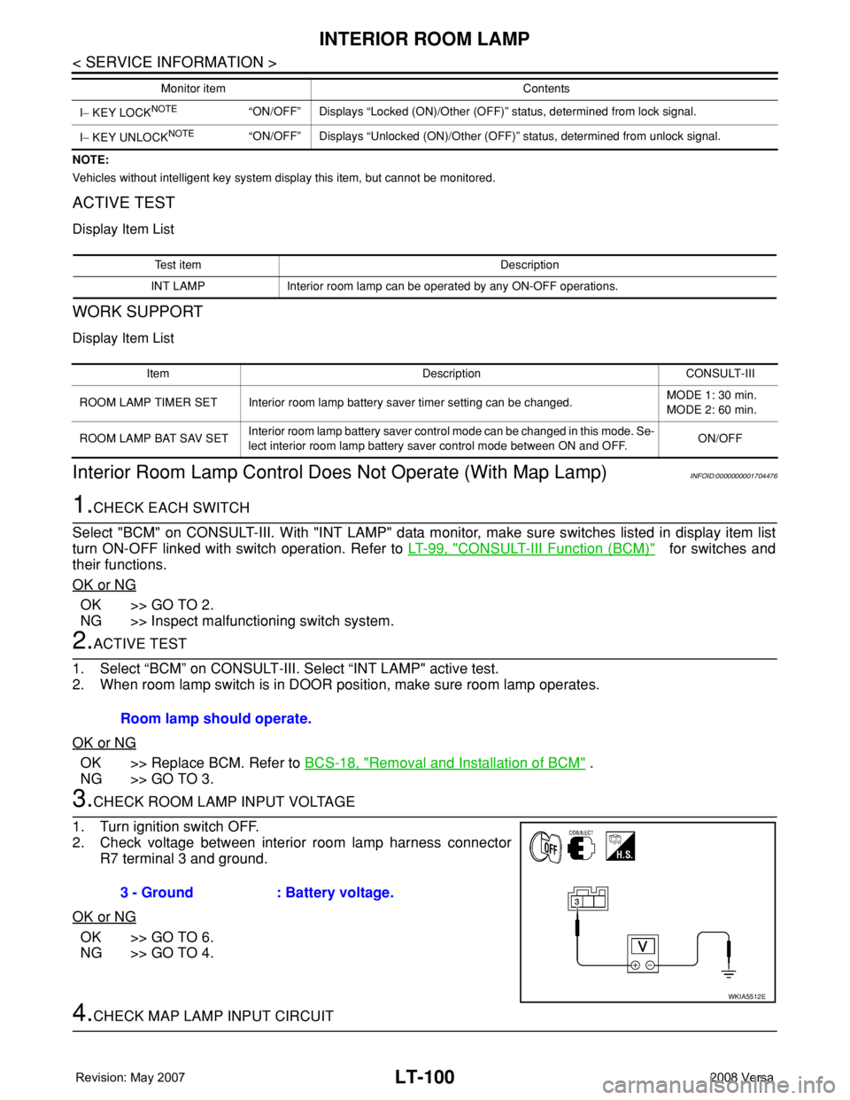
3.CHECK ROOM LAMP INPUT VOLTAGE
1. Turn ignition switch OFF.
2. Check voltage between interior room lamp harness connector
R7 terminal 3 and ground.
OK or NG
OK >> GO TO 6.
NG >> GO TO 4.
4.CHECK MAP LAMP INPUT CIRCUIT
I− KEY LOCKNOTE“ON/OFF” Displays “Locked (ON)/Other (OFF)” status, determined from lock signal.
I− KEY UNLOCK
NOTE“ON/OFF” Displays “Unlocked (ON)/Other (OFF)” status, determined from unlock signal. Monitor item Contents
Test item Description
INT LAMP Interior room lamp can be operated by any ON-OFF operations.
Item Description CONSULT-III
ROOM LAMP TIMER SET Interior room lamp battery saver timer setting can be changed.MODE 1: 30 min.
MODE 2: 60 min.
ROOM LAMP BAT SAV SETInterior room lamp battery saver control mode can be changed in this mode. Se-
lect interior room lamp battery saver control mode between ON and OFF.ON/OFF
Room lamp should operate.
3 - Ground : Battery voltage.
WKIA5512E
Page 2238 of 2771
INTERIOR ROOM LAMP
LT-101
< SERVICE INFORMATION >
C
D
E
F
G
H
I
J
L
MA
B
LT
N
O
P
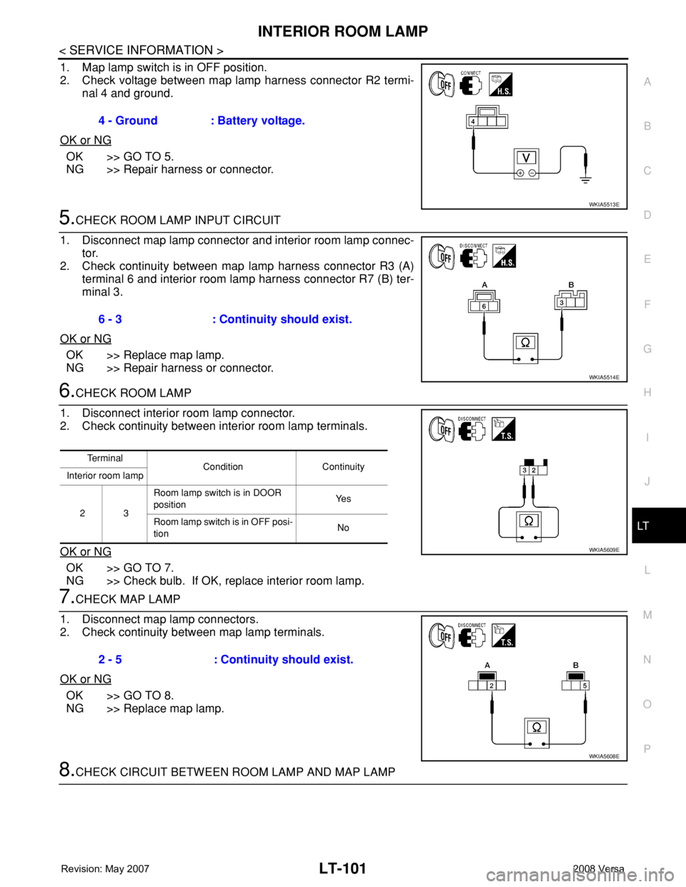
1. Map lamp switch is in OFF position.
2. Check voltage between map lamp harness connector R2 termi-
nal 4 and ground.
OK or NG
OK >> GO TO 5.
NG >> Repair harness or connector.
5.CHECK ROOM LAMP INPUT CIRCUIT
1. Disconnect map lamp connector and interior room lamp connec-
tor.
2. Check continuity between map lamp harness connector R3 (A)
terminal 6 and interior room lamp harness connector R7 (B) ter-
minal 3.
OK or NG
OK >> Replace map lamp.
NG >> Repair harness or connector.
6.CHECK ROOM LAMP
1. Disconnect interior room lamp connector.
2. Check continuity between interior room lamp terminals.
OK or NG
OK >> GO TO 7.
NG >> Check bulb. If OK, replace interior room lamp.
7.CHECK MAP LAMP
1. Disconnect map lamp connectors.
2. Check continuity between map lamp terminals.
OK or NG
OK >> GO TO 8.
NG >> Replace map lamp.
8.CHECK CIRCUIT BETWEEN ROOM LAMP AND MAP LAMP 4 - Ground : Battery voltage.
WKIA5513E
6 - 3 : Continuity should exist.
WKIA5514E
Te r m i n a l
Condition Continuity
Interior room lamp
23Room lamp switch is in DOOR
positionYe s
Room lamp switch is in OFF posi-
tionNo
WKIA5609E
2 - 5 : Continuity should exist.
WKIA5608E
Page 2239 of 2771
LT-102
< SERVICE INFORMATION >
INTERIOR ROOM LAMP
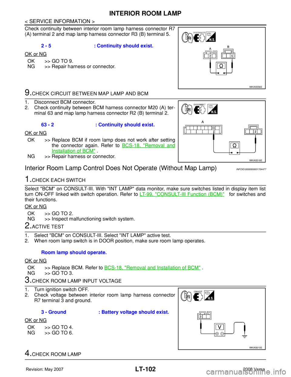
Check continuity between interior room lamp harness connector R7
(A) terminal 2 and map lamp harness connector R3 (B) terminal 5.
OK or NG
OK >> GO TO 9.
NG >> Repair harness or connector.
9.CHECK CIRCUIT BETWEEN MAP LAMP AND BCM
1. Disconnect BCM connector.
2. Check continuity between BCM harness connector M20 (A) ter-
minal 63 and map lamp harness connector R2 (B) terminal 2.
OK or NG
OK >> Replace BCM if room lamp does not work after setting
the connector again. Refer to BCS-18, "
Removal and
Installation of BCM" .
NG >> Repair harness or connector.
Interior Room Lamp Control Does Not Operate (Without Map Lamp)INFOID:0000000001704477
1.CHECK EACH SWITCH
Select "BCM" on CONSULT-III. With "INT LAMP" data monitor, make sure switches listed in display item list
turn ON-OFF linked with switch operation. Refer to LT-99, "
CONSULT-III Function (BCM)" for switches and
their functions.
OK or NG
OK >> GO TO 2.
NG >> Inspect malfunctioning switch system.
2.ACTIVE TEST
1. Select "BCM" on CONSULT-III. Select "INT LAMP" active test.
2. When room lamp switch is in DOOR position, make sure room lamp operates.
OK or NG
OK >> Replace BCM. Refer to BCS-18, "Removal and Installation of BCM" .
NG >> GO TO 3.
3.CHECK ROOM LAMP INPUT VOLTAGE
1. Turn ignition switch OFF.
2. Check voltage between interior room lamp harness connector
R7 terminal 3 and ground.
OK or NG
OK >> GO TO 4.
NG >> GO TO 6.
4.CHECK ROOM LAMP 2 - 5 : Continuity should exist.
WKIA5556E
63 - 2 : Continuity should exist.
WKIA5518E
Room lamp should operate.
3 - Ground : Battery voltage should exist.
WKIA5610E