Page 1248 of 2771
EC-174
< SERVICE INFORMATION >
DTC P0101 MAF SENSOR
b. If NG, repair or replace malfunctioning part and perform step 2 to 4 again.
If OK, go to next step.
6. Turn ignition switch OFF.
7. Disconnect mass air flow sensor harness connector and reconnect it again.
8. Perform step 2 to 4 again.
9. If NG, clean or replace mass air flow sensor.
Without CONSULT-II
1. Reconnect all harness connectors disconnected.
2. Start engine and warm it up to normal operating temperature.
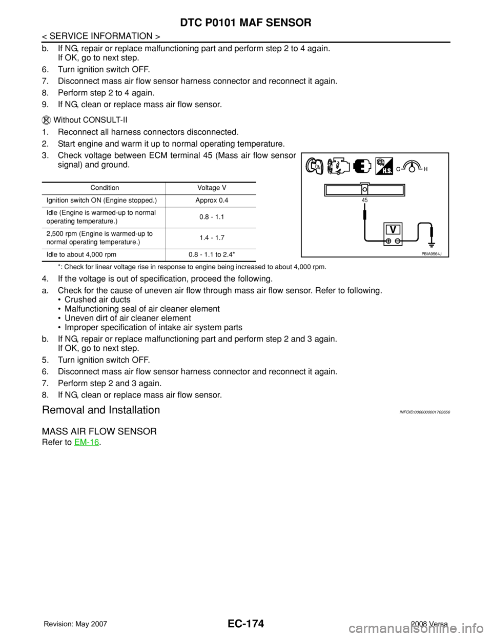
3. Check voltage between ECM terminal 45 (Mass air flow sensor
signal) and ground.
*: Check for linear voltage rise in response to engine being increased to about 4,000 rpm.
4. If the voltage is out of specification, proceed the following.
a. Check for the cause of uneven air flow through mass air flow sensor. Refer to following.
• Crushed air ducts
• Malfunctioning seal of air cleaner element
• Uneven dirt of air cleaner element
• Improper specification of intake air system parts
b. If NG, repair or replace malfunctioning part and perform step 2 and 3 again.
If OK, go to next step.
5. Turn ignition switch OFF.
6. Disconnect mass air flow sensor harness connector and reconnect it again.
7. Perform step 2 and 3 again.
8. If NG, clean or replace mass air flow sensor.
Removal and InstallationINFOID:0000000001702656
MASS AIR FLOW SENSOR
Refer to EM-16.
Condition Voltage V
Ignition switch ON (Engine stopped.) Approx 0.4
Idle (Engine is warmed-up to normal
operating temperature.)0.8 - 1.1
2,500 rpm (Engine is warmed-up to
normal operating temperature.)1.4 - 1.7
Idle to about 4,000 rpm 0.8 - 1.1 to 2.4*
PBIA9564J
Page 1252 of 2771

EC-178
< SERVICE INFORMATION >
DTC P0102, P0103 MAF SENSOR
Diagnosis Procedure
INFOID:0000000001702662
1.INSPECTION START
Which malfunction (P0102 or P0103) is duplicated?
P0102 or P0103
P0102 >> GO TO 2.
P0103 >> GO TO 3.
2.CHECK INTAKE SYSTEM
Check the following for connection.
• Air duct
• Vacuum hoses
• Intake air passage between air duct and intake manifold
OK or NG
OK >> GO TO 3.
NG >> Reconnect the parts.
3.CHECK GROUND CONNECTIONS
1. Turn ignition switch OFF.
2. Loosen and retighten ground screw on the body.
Refer to EC-142, "
Ground Inspection".
TER-
MI-
NAL
NO.WIRE
COLORITEM CONDITION DATA (DC Voltage)
32 PECM relay
(Self shut-off)[Engine is running]
[Ignition switch: OFF]
• For a few seconds after turning ignition
switch OFF0 - 1.0V
[Ignition switch: OFF]
• More than a few seconds after turning igni-
tion switch OFFBATTERY VOLTAGE
(11 - 14V)
45 G Mass air flow sensor[Engine is running]
•Warm-up condition
• Idle speed0.8 - 1.1V
[Engine is running]
•Warm-up condition
• Engine speed: 2,500 rpm1.4 - 1.7V
52 LGSensor ground
(Mass air flow sensor)[Engine is running]
•Warm-up condition
• Idle speedApproximately 0V
105 G Power supply for ECM[Ignition switch: ON]BATTERY VOLTAGE
(11 - 14V)
BBIA0698E
Page 1253 of 2771

DTC P0102, P0103 MAF SENSOR
EC-179
< SERVICE INFORMATION >
C
D
E
F
G
H
I
J
K
L
MA
EC
N
P OOK or NG
OK >> GO TO 4.
NG >> Repair or replace ground connections.
4.CHECK MAF SENSOR POWER SUPPLY CIRCUIT
1. Disconnect mass air flow (MAF) sensor (1) harness connector.
2. Turn ignition switch ON.
3. Check voltage between MAF sensor terminal 2 and ground with
CONSULT-II or tester.
OK or NG
OK >> GO TO 6.
NG >> GO TO 5.
5.DETECT MALFUNCTIONING PART
Check the following.
• Harness connectors E8, F8
• Harness for open or short between mass air flow sensor and ECM
• Harness for open or short between mass air flow sensor and IPDM E/R
>> Repair open circuit or short to ground or short to power in harness or connectors.
6.CHECK MAF SENSOR GROUND CIRCUIT FOR OPEN AND SHORT
1. Turn ignition switch OFF.
2. Disconnect ECM harness connector.
3. Check harness continuity between MAF sensor terminal 3 and ECM terminal 52.
Refer to Wiring Diagram.
4. Also check harness for short to ground and short to power.
OK or NG
OK >> GO TO 7.
NG >> Repair open circuit or short to ground or short to power in harness or connectors.
7.CHECK MAF SENSOR INPUT SIGNAL CIRCUIT FOR OPEN AND SHORT
1. Check harness continuity between MAF sensor terminal 4 and ECM terminal 45.
Refer to Wiring Diagram.
:Vehicle front
1. Body ground E24 2. Engine ground F9 3. Engine ground F16
4. Body ground E15
BBIA0701E
Voltage: Battery voltage
PBIB1168E
Continuity should exist.
Page 1254 of 2771
EC-180
< SERVICE INFORMATION >
DTC P0102, P0103 MAF SENSOR
2. Also check harness for short to ground and short to power.
OK or NG
OK >> GO TO 8.
NG >> Repair open circuit or short to ground or short to power in harness or connectors.
8.CHECK MASS AIR FLOW SENSOR
Refer to EC-180, "
Component Inspection".
OK or NG
OK >> GO TO 9.
NG >> Replace mass air flow sensor.
9.CHECK INTERMITTENT INCIDENT
Refer to EC-136
.
>>INSPECTION END
Component InspectionINFOID:0000000001702663
MASS AIR FLOW SENSOR
With CONSULT-II
1. Reconnect all harness connectors disconnected.
2. Start engine and warm it up to normal operating temperature.
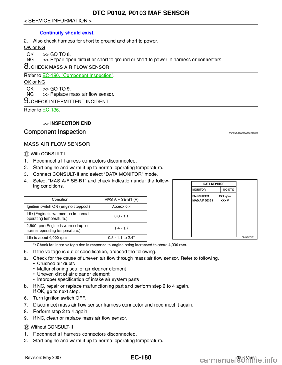
3. Connect CONSULT-II and select “DATA MONITOR” mode.
4. Select “MAS A/F SE-B1” and check indication under the follow-
ing conditions.
*: Check for linear voltage rise in response to engine being increased to about 4,000 rpm.
5. If the voltage is out of specification, proceed the following.
a. Check for the cause of uneven air flow through mass air flow sensor. Refer to following.
• Crushed air ducts
• Malfunctioning seal of air cleaner element
• Uneven dirt of air cleaner element
• Improper specification of intake air system parts
b. If NG, repair or replace malfunctioning part and perform step 2 to 4 again.
If OK, go to next step.
6. Turn ignition switch OFF.
7. Disconnect mass air flow sensor harness connector and reconnect it again.
8. Perform step 2 to 4 again.
9. If NG, clean or replace mass air flow sensor.
Without CONSULT-II
1. Reconnect all harness connectors disconnected.
2. Start engine and warm it up to normal operating temperature.Continuity should exist.
Condition MAS A/F SE-B1 (V)
Ignition switch ON (Engine stopped.) Approx 0.4
Idle (Engine is warmed-up to normal
operating temperature.)0.8 - 1.1
2,500 rpm (Engine is warmed-up to
normal operating temperature.)1.4 - 1.7
Idle to about 4,000 rpm 0.8 - 1.1 to 2.4*
PBIB2371E
Page 1255 of 2771
DTC P0102, P0103 MAF SENSOR
EC-181
< SERVICE INFORMATION >
C
D
E
F
G
H
I
J
K
L
MA
EC
N
P O
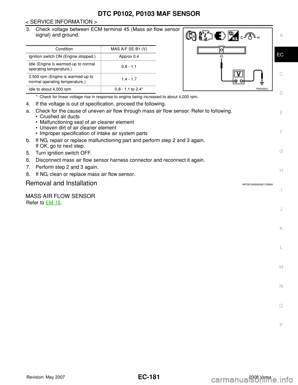
3. Check voltage between ECM terminal 45 (Mass air flow sensor
signal) and ground.
*: Check for linear voltage rise in response to engine being increased to about 4,000 rpm.
4. If the voltage is out of specification, proceed the following.
a. Check for the cause of uneven air flow through mass air flow sensor. Refer to following.
• Crushed air ducts
• Malfunctioning seal of air cleaner element
• Uneven dirt of air cleaner element
• Improper specification of intake air system parts
b. If NG, repair or replace malfunctioning part and perform step 2 and 3 again.
If OK, go to next step.
5. Turn ignition switch OFF.
6. Disconnect mass air flow sensor harness connector and reconnect it again.
7. Perform step 2 and 3 again.
8. If NG, clean or replace mass air flow sensor.
Removal and InstallationINFOID:0000000001702664
MASS AIR FLOW SENSOR
Refer to EM-16.
Condition MAS A/F SE-B1 (V)
Ignition switch ON (Engine stopped.) Approx 0.4
Idle (Engine is warmed-up to normal
operating temperature.)0.8 - 1.1
2,500 rpm (Engine is warmed-up to
normal operating temperature.)1.4 - 1.7
Idle to about 4,000 rpm 0.8 - 1.1 to 2.4*
PBIA9564J
Page 1259 of 2771
DTC P0112, P0113 IAT SENSOR
EC-185
< SERVICE INFORMATION >
C
D
E
F
G
H
I
J
K
L
MA
EC
N
P O
OK or NG
OK >> GO TO 2.
NG >> Repair or replace ground connections.
2.CHECK INTAKE AIR TEMPERATURE SENSOR POWER SUPPLY CIRCUIT
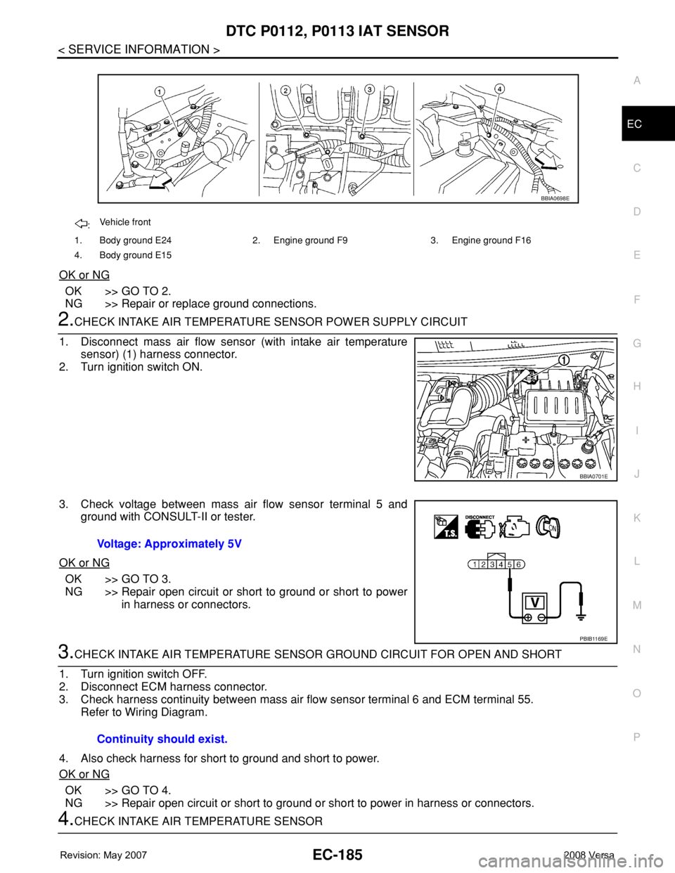
1. Disconnect mass air flow sensor (with intake air temperature
sensor) (1) harness connector.
2. Turn ignition switch ON.
3. Check voltage between mass air flow sensor terminal 5 and
ground with CONSULT-II or tester.
OK or NG
OK >> GO TO 3.
NG >> Repair open circuit or short to ground or short to power
in harness or connectors.
3.CHECK INTAKE AIR TEMPERATURE SENSOR GROUND CIRCUIT FOR OPEN AND SHORT
1. Turn ignition switch OFF.
2. Disconnect ECM harness connector.
3. Check harness continuity between mass air flow sensor terminal 6 and ECM terminal 55.
Refer to Wiring Diagram.
4. Also check harness for short to ground and short to power.
OK or NG
OK >> GO TO 4.
NG >> Repair open circuit or short to ground or short to power in harness or connectors.
4.CHECK INTAKE AIR TEMPERATURE SENSOR
:Vehicle front
1. Body ground E24 2. Engine ground F9 3. Engine ground F16
4. Body ground E15
BBIA0698E
BBIA0701E
Voltage: Approximately 5V
PBIB1169E
Continuity should exist.
Page 1264 of 2771
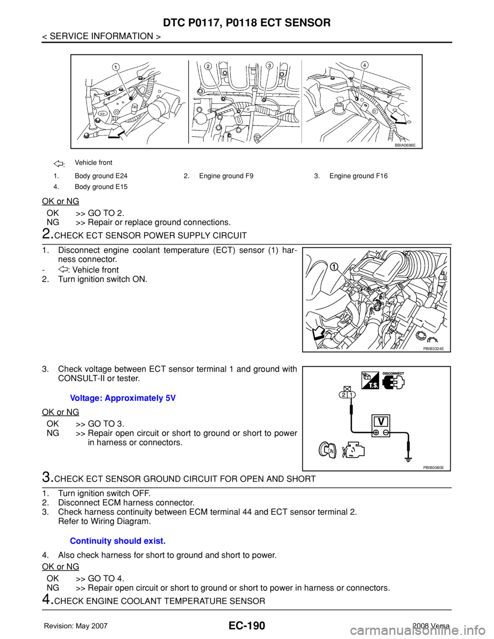
EC-190
< SERVICE INFORMATION >
DTC P0117, P0118 ECT SENSOR
OK or NG
OK >> GO TO 2.
NG >> Repair or replace ground connections.
2.CHECK ECT SENSOR POWER SUPPLY CIRCUIT
1. Disconnect engine coolant temperature (ECT) sensor (1) har-
ness connector.
- : Vehicle front
2. Turn ignition switch ON.
3. Check voltage between ECT sensor terminal 1 and ground with
CONSULT-II or tester.
OK or NG
OK >> GO TO 3.
NG >> Repair open circuit or short to ground or short to power
in harness or connectors.
3.CHECK ECT SENSOR GROUND CIRCUIT FOR OPEN AND SHORT
1. Turn ignition switch OFF.
2. Disconnect ECM harness connector.
3. Check harness continuity between ECM terminal 44 and ECT sensor terminal 2.
Refer to Wiring Diagram.
4. Also check harness for short to ground and short to power.
OK or NG
OK >> GO TO 4.
NG >> Repair open circuit or short to ground or short to power in harness or connectors.
4.CHECK ENGINE COOLANT TEMPERATURE SENSOR
:Vehicle front
1. Body ground E24 2. Engine ground F9 3. Engine ground F16
4. Body ground E15
BBIA0698E
PBIB3324E
Voltage: Approximately 5V
PBIB0080E
Continuity should exist.
Page 1265 of 2771
DTC P0117, P0118 ECT SENSOR
EC-191
< SERVICE INFORMATION >
C
D
E
F
G
H
I
J
K
L
MA
EC
N
P O
Refer to EC-191, "Component Inspection".
OK or NG
OK >> GO TO 5.
NG >> Replace engine coolant temperature sensor.
5.CHECK INTERMITTENT INCIDENT
Refer to EC-136
.
>>INSPECTION END
Component InspectionINFOID:0000000001702677
ENGINE COOLANT TEMPERATURE SENSOR
1. Check resistance between engine coolant temperature sensor
terminals 1 and 2 as shown in the figure.
2. If NG, replace engine coolant temperature sensor.
Removal and InstallationINFOID:0000000001702678
ENGINE COOLANT TEMPERATURE SENSOR
Refer to EM-62.
PBIB2005E
Temperature°C (°F) Resistance kΩ
20 (68) 2.1 - 2.9
50 (122) 0.68 - 1.00
90 (194) 0.236 - 0.260
SEF012P