2008 NISSAN TIIDA fuse diagram
[x] Cancel search: fuse diagramPage 1539 of 2771
DTC P2101 ELECTRIC THROTTLE CONTROL FUNCTION
EC-465
< SERVICE INFORMATION >
C
D
E
F
G
H
I
J
K
L
MA
EC
N
P O
7.DETECT MALFUNCTIONING PART
Check the following.
• Harness connectors E8, F8
• Harness for open or short between ECM and IPDM E/R
>> Repair open circuit or short to ground or short to power in harness or connectors.
8.CHECK FUSE
1. Disconnect 15A fuse.
2. Check 15A fuse for blown.
OK or NG
OK >> GO TO 9.
NG >> Replace 15A fuse.
9.CHECK INTERMITTENT INCIDENT
Refer to EC-136
.
OK or NG
OK >> Replace IPDM E/R. Refer to PG-26, "Removal and Installation of IPDM E/R".
NG >> Repair or replace harness or connectors.
10.CHECK THROTTLE CONTROL MOTOR OUTPUT SIGNAL CIRCUIT FOR OPEN OR SHORT
1. Turn ignition switch OFF.
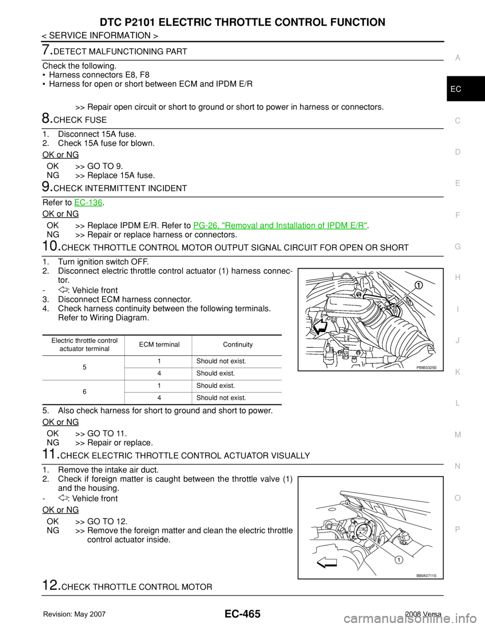
2. Disconnect electric throttle control actuator (1) harness connec-
tor.
- : Vehicle front
3. Disconnect ECM harness connector.
4. Check harness continuity between the following terminals.
Refer to Wiring Diagram.
5. Also check harness for short to ground and short to power.
OK or NG
OK >> GO TO 11.
NG >> Repair or replace.
11 .CHECK ELECTRIC THROTTLE CONTROL ACTUATOR VISUALLY
1. Remove the intake air duct.
2. Check if foreign matter is caught between the throttle valve (1)
and the housing.
- : Vehicle front
OK or NG
OK >> GO TO 12.
NG >> Remove the foreign matter and clean the electric throttle
control actuator inside.
12.CHECK THROTTLE CONTROL MOTOR
Electric throttle control
actuator terminalECM terminal Continuity
51 Should not exist.
4 Should exist.
61 Should exist.
4 Should not exist.
PBIB3325E
BBIA0711E
Page 1579 of 2771
DTC P2A00 A/F SENSOR 1
EC-505
< SERVICE INFORMATION >
C
D
E
F
G
H
I
J
K
L
MA
EC
N
P O
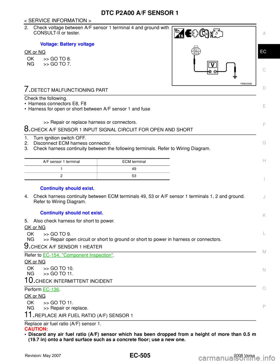
2. Check voltage between A/F sensor 1 terminal 4 and ground with
CONSULT-II or tester.
OK or NG
OK >> GO TO 8.
NG >> GO TO 7.
7.DETECT MALFUNCTIONING PART
Check the following.
• Harness connectors E8, F8
• Harness for open or short between A/F sensor 1 and fuse
>> Repair or replace harness or connectors.
8.CHECK A/F SENSOR 1 INPUT SIGNAL CIRCUIT FOR OPEN AND SHORT
1. Turn ignition switch OFF.
2. Disconnect ECM harness connector.
3. Check harness continuity between the following terminals. Refer to Wiring Diagram.
4. Check harness continuity between ECM terminals 49, 53 or A/F sensor 1 terminals 1, 2 and ground.
Refer to Wiring Diagram.
5. Also check harness for short to power.
OK or NG
OK >> GO TO 9.
NG >> Repair open circuit or short to ground or short to power in harness or connectors.
9.CHECK A/F SENSOR 1 HEATER
Refer to EC-154, "
Component Inspection".
OK or NG
OK >> GO TO 10.
NG >> GO TO 11.
10.CHECK INTERMITTENT INCIDENT
Perform EC-136
.
OK or NG
OK >> GO TO 11.
NG >> Repair or replace.
11 .REPLACE AIR FUEL RATIO (A/F) SENSOR 1
Replace air fuel ratio (A/F) sensor 1.
CAUTION:
• Discard any air fuel ratio (A/F) sensor which has been dropped from a height of more than 0.5 m
(19.7 in) onto a hard surface such as a concrete floor; use a new one. Voltage: Battery voltage
PBIB3308E
A/F sensor 1 terminal ECM terminal
149
253
Continuity should exist.
Continuity should not exist.
Page 1586 of 2771
EC-512
< SERVICE INFORMATION >
ASCD BRAKE SWITCH
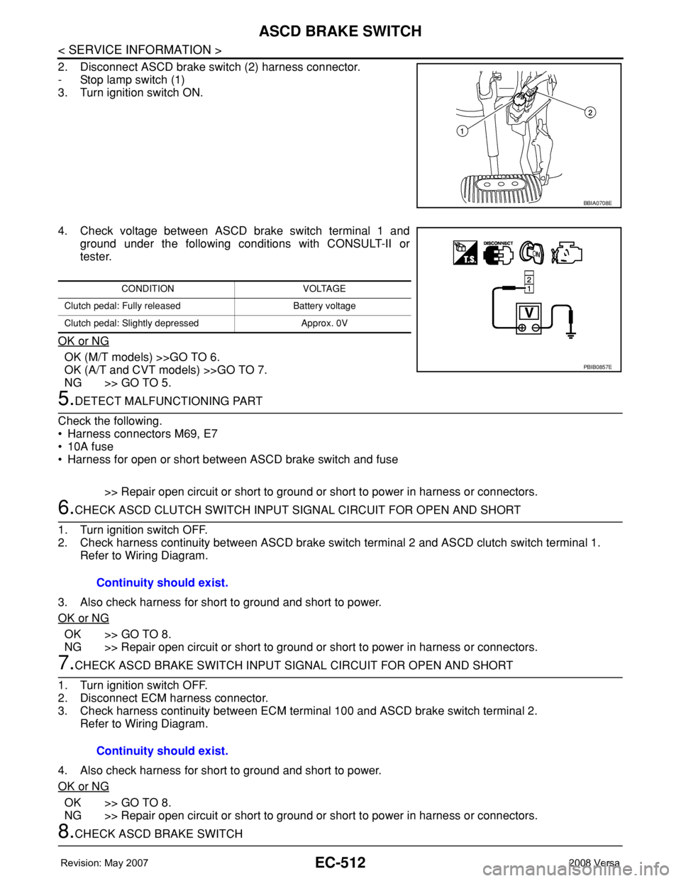
2. Disconnect ASCD brake switch (2) harness connector.
- Stop lamp switch (1)
3. Turn ignition switch ON.
4. Check voltage between ASCD brake switch terminal 1 and
ground under the following conditions with CONSULT-II or
tester.
OK or NG
OK (M/T models) >>GO TO 6.
OK (A/T and CVT models) >>GO TO 7.
NG >> GO TO 5.
5.DETECT MALFUNCTIONING PART
Check the following.
• Harness connectors M69, E7
• 10A fuse
• Harness for open or short between ASCD brake switch and fuse
>> Repair open circuit or short to ground or short to power in harness or connectors.
6.CHECK ASCD CLUTCH SWITCH INPUT SIGNAL CIRCUIT FOR OPEN AND SHORT
1. Turn ignition switch OFF.
2. Check harness continuity between ASCD brake switch terminal 2 and ASCD clutch switch terminal 1.
Refer to Wiring Diagram.
3. Also check harness for short to ground and short to power.
OK or NG
OK >> GO TO 8.
NG >> Repair open circuit or short to ground or short to power in harness or connectors.
7.CHECK ASCD BRAKE SWITCH INPUT SIGNAL CIRCUIT FOR OPEN AND SHORT
1. Turn ignition switch OFF.
2. Disconnect ECM harness connector.
3. Check harness continuity between ECM terminal 100 and ASCD brake switch terminal 2.
Refer to Wiring Diagram.
4. Also check harness for short to ground and short to power.
OK or NG
OK >> GO TO 8.
NG >> Repair open circuit or short to ground or short to power in harness or connectors.
8.CHECK ASCD BRAKE SWITCH
BBIA0708E
CONDITION VOLTAGE
Clutch pedal: Fully released Battery voltage
Clutch pedal: Slightly depressed Approx. 0V
PBIB0857E
Continuity should exist.
Continuity should exist.
Page 1598 of 2771
EC-524
< SERVICE INFORMATION >
FUEL INJECTOR
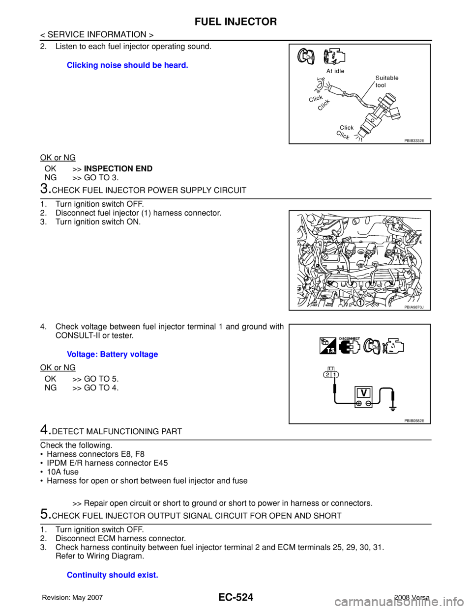
2. Listen to each fuel injector operating sound.
OK or NG
OK >>INSPECTION END
NG >> GO TO 3.
3.CHECK FUEL INJECTOR POWER SUPPLY CIRCUIT
1. Turn ignition switch OFF.
2. Disconnect fuel injector (1) harness connector.
3. Turn ignition switch ON.
4. Check voltage between fuel injector terminal 1 and ground with
CONSULT-II or tester.
OK or NG
OK >> GO TO 5.
NG >> GO TO 4.
4.DETECT MALFUNCTIONING PART
Check the following.
• Harness connectors E8, F8
• IPDM E/R harness connector E45
• 10A fuse
• Harness for open or short between fuel injector and fuse
>> Repair open circuit or short to ground or short to power in harness or connectors.
5.CHECK FUEL INJECTOR OUTPUT SIGNAL CIRCUIT FOR OPEN AND SHORT
1. Turn ignition switch OFF.
2. Disconnect ECM harness connector.
3. Check harness continuity between fuel injector terminal 2 and ECM terminals 25, 29, 30, 31.
Refer to Wiring Diagram.Clicking noise should be heard.
PBIB3332E
PBIA9870J
Voltage: Battery voltage
PBIB0582E
Continuity should exist.
Page 1603 of 2771
FUEL PUMP
EC-529
< SERVICE INFORMATION >
C
D
E
F
G
H
I
J
K
L
MA
EC
N
P O
4.DETECT MALFUNCTIONING PART
Check the following.
• Harness connectors E8, F8
• Harness for open or short between IPDM E/R and ECM
>> Repair open circuit or short to ground or short to power in harness or connectors.
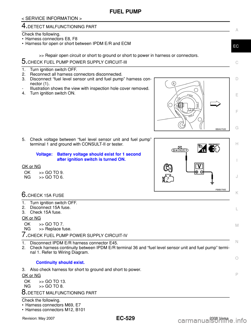
5.CHECK FUEL PUMP POWER SUPPLY CIRCUIT-III
1. Turn ignition switch OFF.
2. Reconnect all harness connectors disconnected.
3. Disconnect “fuel level sensor unit and fuel pump” harness con-
nector (1).
- Illustration shows the view with inspection hole cover removed.
4. Turn ignition switch ON.
5. Check voltage between “fuel level sensor unit and fuel pump”
terminal 1 and ground with CONSULT-II or tester.
OK or NG
OK >> GO TO 9.
NG >> GO TO 6.
6.CHECK 15A FUSE
1. Turn ignition switch OFF.
2. Disconnect 15A fuse.
3. Check 15A fuse.
OK or NG
OK >> GO TO 7.
NG >> Replace fuse.
7.CHECK FUEL PUMP POWER SUPPLY CIRCUIT-IV
1. Disconnect IPDM E/R harness connector E45.
2. Check harness continuity between IPDM E/R terminal 36 and “fuel level sensor unit and fuel pump” termi-
nal 1. Refer to Wiring Diagram.
3. Also check harness for short to ground and short to power.
OK or NG
OK >> GO TO 13.
NG >> GO TO 8.
8.DETECT MALFUNCTIONING PART
Check the following.
• Harness connectors M69, E7
• Harness connectors M12, B101
BBIA0702E
Voltage: Battery voltage should exist for 1 second
after ignition switch is turned ON.
PBIB0795E
Continuity should exist.
Page 1868 of 2771
HOW TO USE THIS MANUAL
GI-17
< SERVICE INFORMATION >
C
D
E
F
G
H
I
J
K
L
MB
GI
N
O
P
Harness Indication
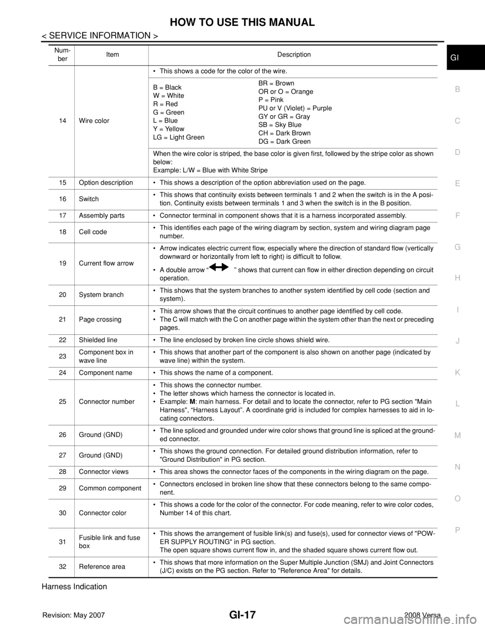
14 Wire color• This shows a code for the color of the wire.
B = Black
W = White
R = Red
G = Green
L = Blue
Y = Yellow
LG = Light GreenBR = Brown
OR or O = Orange
P = Pink
PU or V (Violet) = Purple
GY or GR = Gray
SB = Sky Blue
CH = Dark Brown
DG = Dark Green
When the wire color is striped, the base color is given first, followed by the stripe color as shown
below:
Example: L/W = Blue with White Stripe
15 Option description • This shows a description of the option abbreviation used on the page.
16 Switch• This shows that continuity exists between terminals 1 and 2 when the switch is in the A posi-
tion. Continuity exists between terminals 1 and 3 when the switch is in the B position.
17 Assembly parts • Connector terminal in component shows that it is a harness incorporated assembly.
18 Cell code• This identifies each page of the wiring diagram by section, system and wiring diagram page
number.
19 Current flow arrow• Arrow indicates electric current flow, especially where the direction of standard flow (vertically
downward or horizontally from left to right) is difficult to follow.
• A double arrow “ ” shows that current can flow in either direction depending on circuit
operation.
20 System branch• This shows that the system branches to another system identified by cell code (section and
system).
21 Page crossing• This arrow shows that the circuit continues to another page identified by cell code.
• The C will match with the C on another page within the system other than the next or preceding
pages.
22 Shielded line • The line enclosed by broken line circle shows shield wire.
23Component box in
wave line• This shows that another part of the component is also shown on another page (indicated by
wave line) within the system.
24 Component name • This shows the name of a component.
25 Connector number• This shows the connector number.
• The letter shows which harness the connector is located in.
•Example: M: main harness. For detail and to locate the connector, refer to PG section "Main
Harness", “Harness Layout”. A coordinate grid is included for complex harnesses to aid in lo-
cating connectors.
26 Ground (GND)• The line spliced and grounded under wire color shows that ground line is spliced at the ground-
ed connector.
27 Ground (GND)• This shows the ground connection. For detailed ground distribution information, refer to
"Ground Distribution" in PG section.
28 Connector views • This area shows the connector faces of the components in the wiring diagram on the page.
29 Common component• Connectors enclosed in broken line show that these connectors belong to the same compo-
nent.
30 Connector color• This shows a code for the color of the connector. For code meaning, refer to wire color codes,
Number 14 of this chart.
31Fusible link and fuse
box• This shows the arrangement of fusible link(s) and fuse(s), used for connector views of "POW-
ER SUPPLY ROUTING" in PG section.
The open square shows current flow in, and the shaded square shows current flow out.
32 Reference area• This shows that more information on the Super Multiple Junction (SMJ) and Joint Connectors
(J/C) exists on the PG section. Refer to "Reference Area" for details. Num-
berItem Description
Page 2434 of 2771
PG-1
ELECTRICAL
C
D
E
F
G
H
I
J
L
M
SECTION PG
A
B
PG
N
O
P
CONTENTS
POWER SUPPLY, GROUND & CIRCUIT ELEMENTS
SERVICE INFORMATION ............................2
PRECAUTIONS ...................................................2
Precaution for Supplemental Restraint System
(SRS) "AIR BAG" and "SEAT BELT PRE-TEN-
SIONER" ...................................................................
2
POWER SUPPLY ROUTING CIRCUIT ...............3
Schematic .................................................................3
Wiring Diagram - POWER - ......................................5
Fuse ........................................................................15
Fusible Link .............................................................15
Circuit Breaker (Built Into BCM) ..............................15
Circuit Breaker ........................................................15
IPDM E/R (INTELLIGENT POWER DISTRI-
BUTION MODULE ENGINE ROOM) .................
16
System Description .................................................16
CAN Communication System Description ...............17
Function of Detecting Ignition Relay Malfunction ....17
CONSULT-III Function (IPDM E/R) .........................17
Auto Active Test ......................................................19
IPDM E/R Terminal Arrangement ...........................22
Terminal and Reference Value for IPDM E/R .........23
IPDM E/R Power/Ground Circuit Inspection ...........25
Inspection with CONSULT-III (Self-Diagnosis) .......26
Removal and Installation of IPDM E/R ....................26
GROUND CIRCUIT ...........................................28
Ground Distribution ..................................................28
HARNESS .........................................................37
Harness Layout .......................................................37
Wiring Diagram Codes (Cell Codes) .......................58
ELECTRICAL UNITS LOCATION ....................61
Electrical Units Location ..........................................61
HARNESS CONNECTOR .................................65
Description ...............................................................65
ELECTRICAL UNITS ........................................68
Terminal Arrangement .............................................68
STANDARDIZED RELAY .................................69
Description ...............................................................69
SUPER MULTIPLE JUNCTION (SMJ) .............71
Terminal Arrangement .............................................71
FUSE BLOCK-JUNCTION BOX (J/B) ..............72
Terminal Arrangement .............................................72
FUSE AND FUSIBLE LINK BOX ......................73
Terminal Arrangement .............................................73