2008 NISSAN TIIDA Pressure
[x] Cancel search: PressurePage 47 of 2771
A/T CONTROL SYSTEM
AT-35
< SERVICE INFORMATION >
D
E
F
G
H
I
J
K
L
MA
B
AT
N
O
P
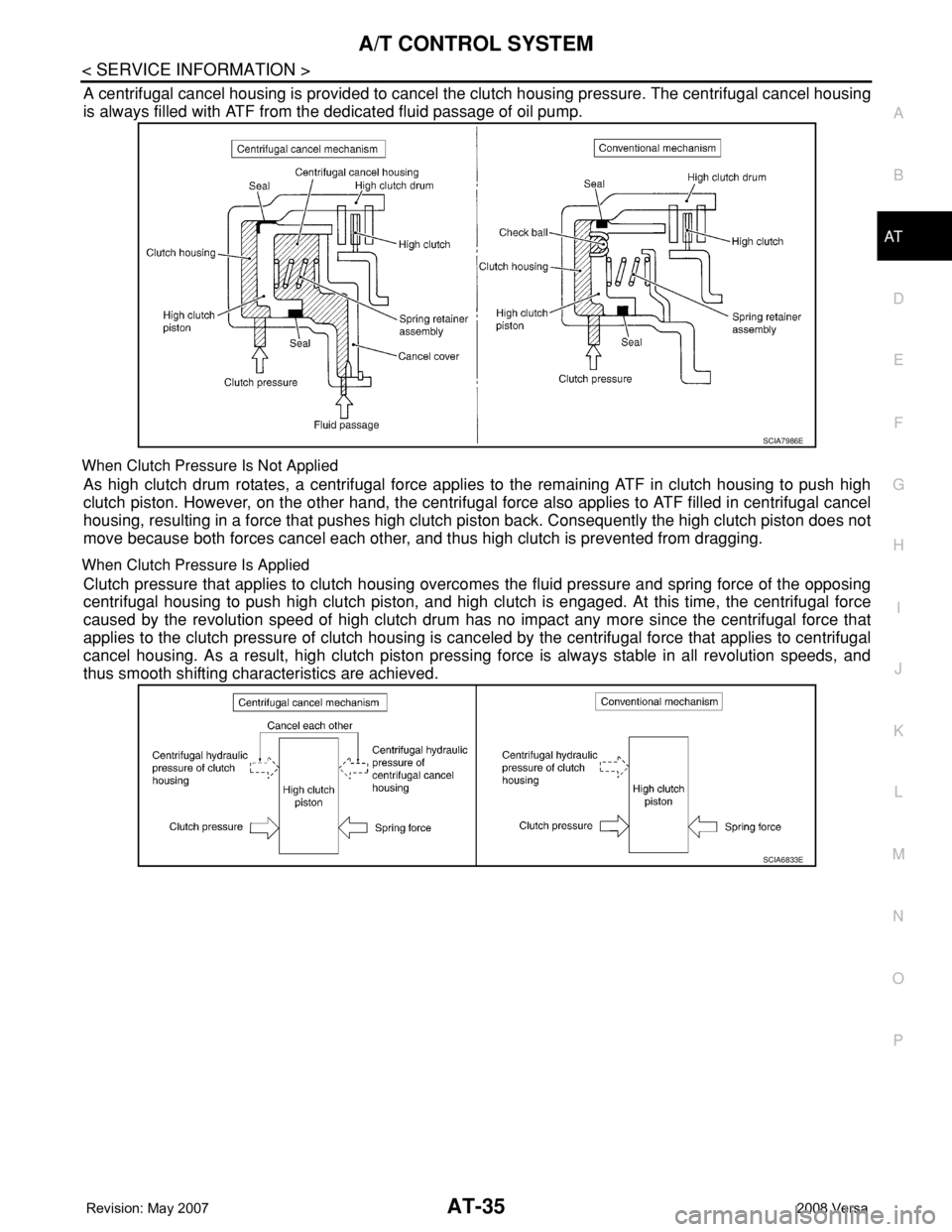
A centrifugal cancel housing is provided to cancel the clutch housing pressure. The centrifugal cancel housing
is always filled with ATF from the dedicated fluid passage of oil pump.
When Clutch Pressure Is Not Applied
As high clutch drum rotates, a centrifugal force applies to the remaining ATF in clutch housing to push high
clutch piston. However, on the other hand, the centrifugal force also applies to ATF filled in centrifugal cancel
housing, resulting in a force that pushes high clutch piston back. Consequently the high clutch piston does not
move because both forces cancel each other, and thus high clutch is prevented from dragging.
When Clutch Pressure Is Applied
Clutch pressure that applies to clutch housing overcomes the fluid pressure and spring force of the opposing
centrifugal housing to push high clutch piston, and high clutch is engaged. At this time, the centrifugal force
caused by the revolution speed of high clutch drum has no impact any more since the centrifugal force that
applies to the clutch pressure of clutch housing is canceled by the centrifugal force that applies to centrifugal
cancel housing. As a result, high clutch piston pressing force is always stable in all revolution speeds, and
thus smooth shifting characteristics are achieved.
SCIA7986E
SCIA6833E
Page 52 of 2771

AT-40
< SERVICE INFORMATION >
TROUBLE DIAGNOSIS
●: Solenoid ON
×: Solenoid OFF
–: Non-standard condition
Line Pressure Solenoid Valve
If non-standard solenoid signal is sent to TCM, line pressure solenoid valve is turned OFF to achieve maxi-
mum oil pressure.
Torque Converter Clutch Solenoid Valve
If non-standard solenoid signal is sent to TCM, torque converter clutch solenoid valve is turned OFF to release
lock-up.
Overrun Clutch Solenoid Valve
If non-standard solenoid signal is sent to TCM, overrun clutch solenoid valve is turned OFF to engage overrun
clutch. This will result in more effective engine brake during deceleration.
How to Perform Trouble Diagnosis for Quick and Accurate RepairINFOID:0000000001703179
INTRODUCTION
The TCM receives a signal from the vehicle speed sensor, accelera-
tor pedal position sensor or PNP switch and provides shift control or
lock-up control via A/T solenoid valves.
The TCM also communicates with the ECM by means of a signal
sent from sensing elements used with the OBD-related parts of the
A/T system for malfunction-diagnostic purposes. The TCM is capa-
ble of diagnosing malfunctioning parts while the ECM can store mal-
functions in its memory.
Input and output signals must always be correct and stable in the
operation of the A/T system. The A/T system must be in good oper-
ating condition and be free of valve seizure, solenoid valve malfunc-
tion, etc.
It is much more difficult to diagnose a malfunction that occurs intermittently rather than continuously. Most
intermittent malfunctions are caused by poor electric connections or improper wiring. In this case, careful
checking of suspected circuits may help prevent the replacement of good parts.
Shift positionNormalMalfunction in solenoid
valve AMalfunction in solenoid
valve BMalfunction in solenoid
valves A and B
A B Gear A B Gear A B Gear A B Gear
“D” position●●1st –●→×
3rd ●→×–
3rd ––
3rd ×●2nd –●→× ×–––
××3rd – x×–––
●×4th – x●→×–––
“2” position●●1st –●→×●→×–––
×●2nd –●→× ×–––
××3rd – x×–––
“1” position●●1st –●→×●→×–––
×●2nd –●→× ×–––
××3rd – x×–––
SAT631IA
Page 55 of 2771

TROUBLE DIAGNOSIS
AT-43
< SERVICE INFORMATION >
D
E
F
G
H
I
J
K
L
MA
B
AT
N
O
P Diagnostic Worksheet Chart
Customer name MR./MS Model & Year VIN
Trans. model Engine Mileage
Incident Date Manuf. Date In Service Date
Frequency❏ Continuous❏ Intermittent ( times a day)
Symptoms❏ Vehicle does not move. (❏ Any position❏ Particular position)
❏ No up-shift (❏ 1st → 2nd❏ 2nd → 3rd❏ 3rd → 4th)
❏ No down-shift (❏ 4th → 3rd❏ 3rd → 2nd❏ 2nd → 1st)
❏ Lock-up malfunction
❏ Shift point too high or too low.
❏ Shift shock or slip (❏ N → D❏ Lock-up❏ Any drive position)
❏ Noise or vibration
❏ No kick down
❏ No pattern select
❏ Others
()
Malfunction indicator lamp (MIL)❏ Continuously lit❏ Not lit
1.❏ Read the Fail-safe and listen to customer complaints.AT- 3 9,
"Information
from custom-
er"
2.❏ Check A/T fluidMA-22
❏ Leakage (Follow specified procedure)
❏ Fluid condition
❏ Fluid level
3.❏ Perform “STALL TEST” and “LINE PRESSURE TEST”.AT- 4 8
,
AT- 4 8
❏“STALL TEST”— Mark possible damaged components/others.
❏ Torque converter one-way clutch
❏ Reverse clutch
❏ Forward clutch
❏ Overrun clutch
❏ Forward one-way clutch❏ Low & reverse brake
❏ Low one-way clutch
❏ Engine
❏ Line pressure is low
❏ Clutches and brakes except high clutch and
brake band are OK
❏“LINE PRESSURE TEST”— Suspected parts:
Page 62 of 2771
AT-50
< SERVICE INFORMATION >
TROUBLE DIAGNOSIS
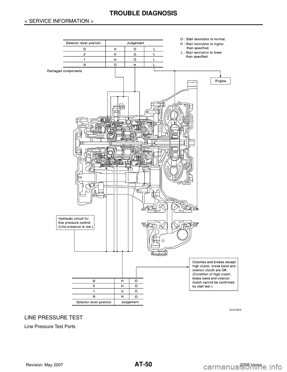
LINE PRESSURE TEST
Line Pressure Test Ports
SCIA7987E
Page 63 of 2771
TROUBLE DIAGNOSIS
AT-51
< SERVICE INFORMATION >
D
E
F
G
H
I
J
K
L
MA
B
AT
N
O
P
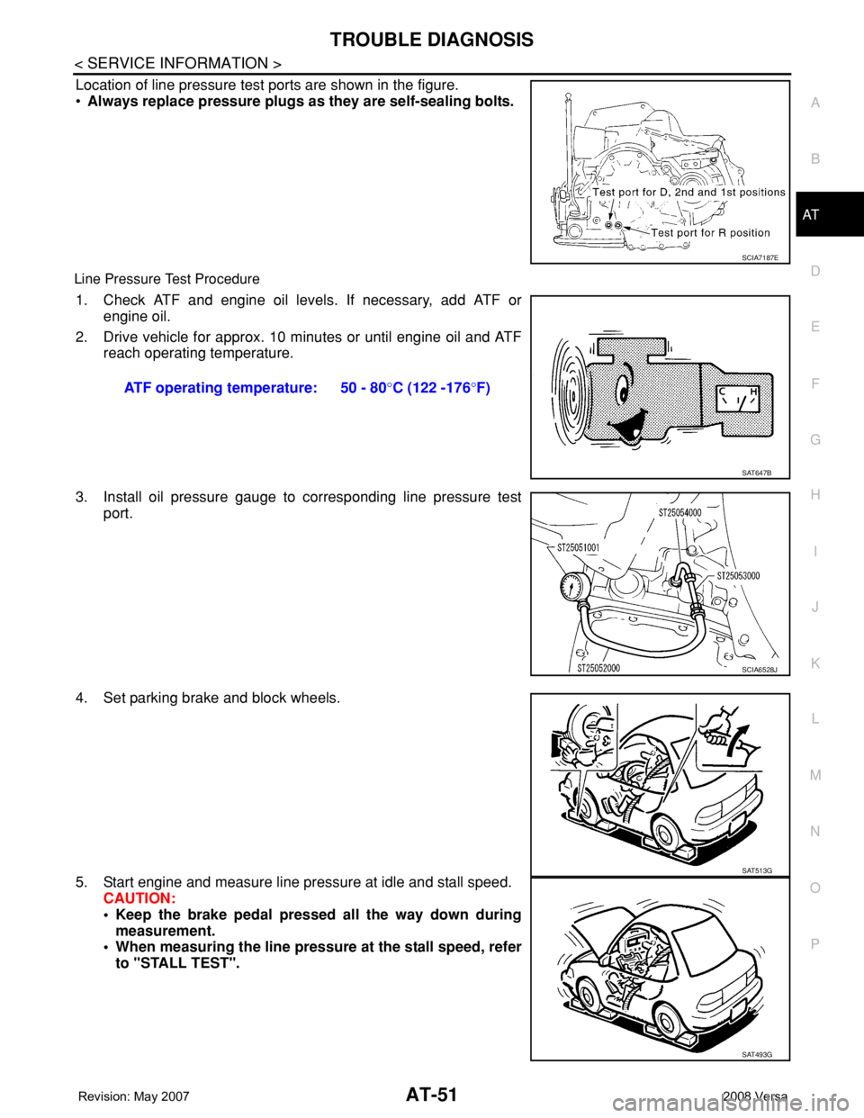
Location of line pressure test ports are shown in the figure.
•Always replace pressure plugs as they are self-sealing bolts.
Line Pressure Test Procedure
1. Check ATF and engine oil levels. If necessary, add ATF or
engine oil.
2. Drive vehicle for approx. 10 minutes or until engine oil and ATF
reach operating temperature.
3. Install oil pressure gauge to corresponding line pressure test
port.
4. Set parking brake and block wheels.
5. Start engine and measure line pressure at idle and stall speed.
CAUTION:
• Keep the brake pedal pressed all the way down during
measurement.
• When measuring the line pressure at the stall speed, refer
to "STALL TEST".
SCIA7187E
ATF operating temperature: 50 - 80°C (122 -176°F)
SAT647B
SCIA6528J
SAT513G
SAT493G
Page 64 of 2771
AT-52
< SERVICE INFORMATION >
TROUBLE DIAGNOSIS
Line Pressure
Judgement of Line Pressure Test
Road TestINFOID:0000000001703183
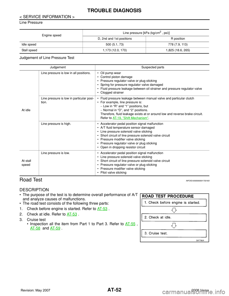
DESCRIPTION
• The purpose of the test is to determine overall performance of A/T
and analyze causes of malfunctions.
• The road test consists of the following three parts:
1. Check before engine is started. Refer to AT- 5 3
.
2. Check at idle. Refer to AT- 5 3
.
3. Cruise test
• Inspection all the item from Part 1 to Part 3. Refer to AT- 5 5
,
AT- 5 8
and AT- 5 9 .
Engine speedLine pressure [kPa (kg/cm
2 , psi)]
D, 2nd and 1st positions R position
Idle speed 500 (5.1, 73) 778 (7.9, 113)
Stall speed 1,173 (12.0, 170) 1,825 (18.6, 265)
Judgement Suspected parts
At idleLine pressure is low in all positions. • Oil pump wear
• Control piston damage
• Pressure regulator valve or plug sticking
• Spring for pressure regulator valve damaged
• Fluid pressure leakage between oil strainer and pressure regulator valve
• Clogged strainer
Line pressure is low in particular posi-
tion.• Fluid pressure leakage between manual valve and particular clutch
• For example, line pressure is:
− Low in “R” and “1” positions, but
− Normal in “D”, and “2” positions.
Therefore, fluid leakage exists at or around low and reverse brake circuit.
Refer to AT- 1 9 , "
Shift Mechanism".
Line pressure is high. • Accelerator pedal position signal malfunction
• A/T fluid temperature sensor damaged
• Line pressure solenoid valve sticking
• Short circuit of line pressure solenoid valve circuit
• Pressure modifier valve sticking
• Pressure regulator valve or plug sticking
• Open in dropping resistor circuit
At stall
speedLine pressure is low. • Accelerator pedal position signal malfunction
• Line pressure solenoid valve sticking
• Short circuit of line pressure solenoid valve circuit
• Pressure regulator valve or plug sticking
• Pressure modifier valve sticking
• Pilot valve sticking
SAT786A
Page 74 of 2771

AT-62
< SERVICE INFORMATION >
TROUBLE DIAGNOSIS
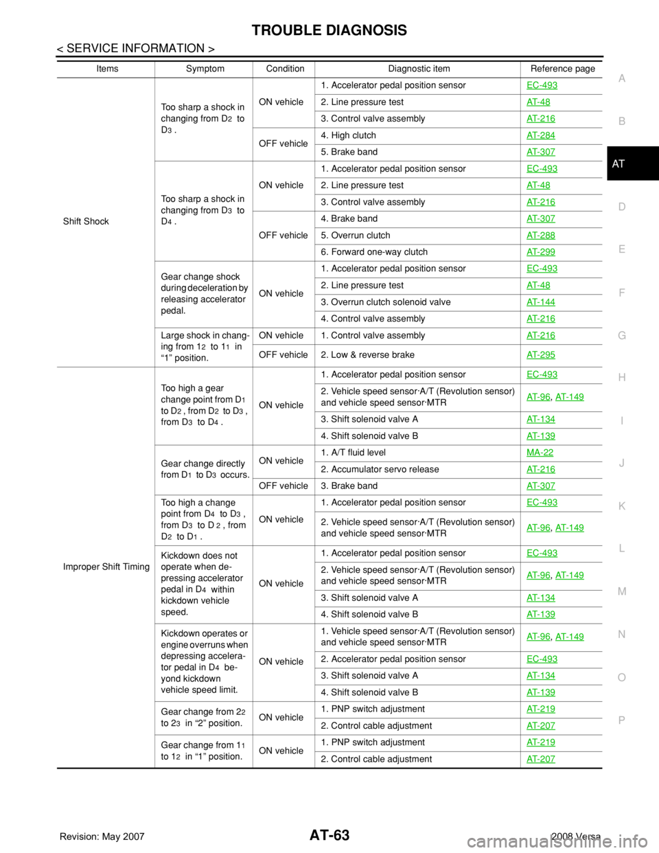
Perform inspections starting with number one and work up.
Items Symptom Condition Diagnostic item Reference page
No Lock-up Engage-
ment/TCC InoperativeTorque converter is
not locked up.ON vehicle1. Accelerator pedal position sensorEC-493
2. Vehicle speed sensor·A/T (Revolution sensor)
and vehicle speed sensor·MTRAT- 9 6, AT- 1 4 9
3. Engine speed signalAT- 1 0 1
4. A/T fluid temperature sensorAT- 9 1
5. Line pressure testAT- 4 8
6. Torque converter clutch solenoid valveAT- 11 9
7. Control valve assemblyAT- 2 1 6
OFF vehicle 8. Torque converterAT- 2 4 0
Torque converter
clutch piston slip.ON vehicle1. A/T fluid levelMA-22
2. Accelerator pedal position sensorEC-493
3. Line pressure testAT- 4 8
4. Torque converter clutch solenoid valveAT- 11 9
5. Line pressure solenoid valveAT- 1 2 9
6. Control valve assemblyAT- 2 1 6
OFF vehicle 7. Torque converterAT- 2 4 0
Lock-up point is ex-
tremely high or low.ON vehicle1. Accelerator pedal position sensorEC-4932. Vehicle speed sensor·A/T (Revolution sensor)
and vehicle speed sensor·MTRAT- 9 6, AT- 1 4 9
3. Torque converter clutch solenoid valveAT- 11 9
4. Control valve assemblyAT- 2 1 6
Shift ShockSharp shock in shift-
ing from “N” to “D” po-
sition.ON vehicle1. Engine idling speedEC-73
2. Accelerator pedal position sensorEC-493
3. Line pressure testAT- 4 8
4. A/T fluid temperature sensorAT- 9 1
5. Engine speed signalAT- 1 0 1
6. Line pressure solenoid valveAT- 1 2 9
7. Control valve assemblyAT- 2 1 6
8. Accumulator N-DAT- 2 1 6
OFF vehicle 9. Forward clutchAT- 2 8 8
Too sharp a shock in
changing from D
1 to
D
2 .ON vehicle1. Accelerator pedal position sensorEC-493
2. Line pressure testAT- 4 8
3. Accumulator servo releaseAT- 2 1 6
4. Control valve assemblyAT- 2 1 6
5. A/T fluid temperature sensorAT- 9 1
OFF vehicle 6. Brake bandAT- 3 0 7
Page 75 of 2771
TROUBLE DIAGNOSIS
AT-63
< SERVICE INFORMATION >
D
E
F
G
H
I
J
K
L
MA
B
AT
N
O
P
Shift ShockToo sharp a shock in
changing from D
2 to
D
3 .ON vehicle1. Accelerator pedal position sensorEC-493
2. Line pressure testAT- 4 8
3. Control valve assemblyAT- 2 1 6
OFF vehicle4. High clutchAT- 2 8 45. Brake bandAT- 3 0 7
Too sharp a shock in
changing from D
3 to
D
4 .ON vehicle1. Accelerator pedal position sensorEC-493
2. Line pressure testAT- 4 8
3. Control valve assemblyAT- 2 1 6
OFF vehicle4. Brake bandAT- 3 0 75. Overrun clutchAT- 2 8 8
6. Forward one-way clutchAT- 2 9 9
Gear change shock
during deceleration by
releasing accelerator
pedal.ON vehicle1. Accelerator pedal position sensorEC-4932. Line pressure testAT- 4 8
3. Overrun clutch solenoid valveAT- 1 4 4
4. Control valve assemblyAT- 2 1 6
Large shock in chang-
ing from 1
2 to 11 in
“1” position.ON vehicle 1. Control valve assemblyAT- 2 1 6OFF vehicle 2. Low & reverse brakeAT- 2 9 5
Improper Shift TimingToo high a gear
change point from D
1
to D
2 , from D2 to D3 ,
from D
3 to D4 .ON vehicle1. Accelerator pedal position sensorEC-493
2. Vehicle speed sensor·A/T (Revolution sensor)
and vehicle speed sensor·MTRAT- 9 6, AT- 1 4 9
3. Shift solenoid valve AAT- 1 3 4
4. Shift solenoid valve BAT- 1 3 9
Gear change directly
from D
1 to D3 occurs.ON vehicle1. A/T fluid levelMA-222. Accumulator servo releaseAT- 2 1 6
OFF vehicle 3. Brake bandAT- 3 0 7
Too high a change
point from D
4 to D3 ,
from D
3 to D 2 , from
D
2 to D1 .ON vehicle1. Accelerator pedal position sensorEC-493
2. Vehicle speed sensor·A/T (Revolution sensor)
and vehicle speed sensor·MTRAT- 9 6, AT- 1 4 9
Kickdown does not
operate when de-
pressing accelerator
pedal in D
4 within
kickdown vehicle
speed.ON vehicle1. Accelerator pedal position sensorEC-493
2. Vehicle speed sensor·A/T (Revolution sensor)
and vehicle speed sensor·MTRAT- 9 6, AT- 1 4 9
3. Shift solenoid valve AAT- 1 3 4
4. Shift solenoid valve BAT- 1 3 9
Kickdown operates or
engine overruns when
depressing accelera-
tor pedal in D
4 be-
yond kickdown
vehicle speed limit.ON vehicle1. Vehicle speed sensor·A/T (Revolution sensor)
and vehicle speed sensor·MTRAT- 9 6
, AT- 1 4 9
2. Accelerator pedal position sensorEC-493
3. Shift solenoid valve AAT- 1 3 4
4. Shift solenoid valve BAT- 1 3 9
Gear change from 22
to 2
3 in “2” position.ON vehicle1. PNP switch adjustmentAT- 2 1 92. Control cable adjustmentAT- 2 0 7
Gear change from 11
to 1
2 in “1” position.ON vehicle1. PNP switch adjustmentAT- 2 1 92. Control cable adjustmentAT- 2 0 7
Items Symptom Condition Diagnostic item Reference page