2008 NISSAN TIIDA spare tire
[x] Cancel search: spare tirePage 2183 of 2771
LT-46
< SERVICE INFORMATION >
FRONT FOG LAMP
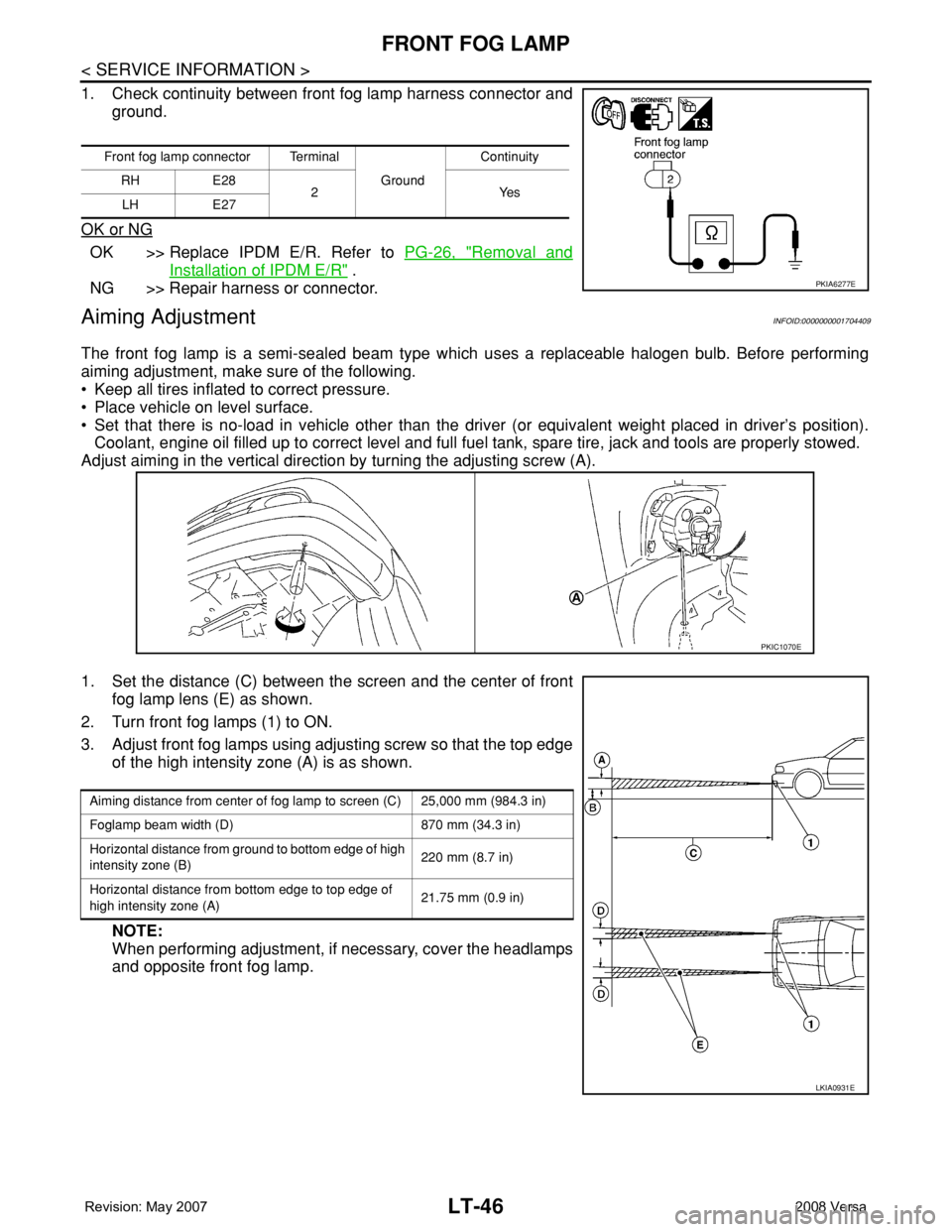
1. Check continuity between front fog lamp harness connector and
ground.
OK or NG
OK >> Replace IPDM E/R. Refer to PG-26, "Removal and
Installation of IPDM E/R" .
NG >> Repair harness or connector.
Aiming AdjustmentINFOID:0000000001704409
The front fog lamp is a semi-sealed beam type which uses a replaceable halogen bulb. Before performing
aiming adjustment, make sure of the following.
• Keep all tires inflated to correct pressure.
• Place vehicle on level surface.
• Set that there is no-load in vehicle other than the driver (or equivalent weight placed in driver’s position).
Coolant, engine oil filled up to correct level and full fuel tank, spare tire, jack and tools are properly stowed.
Adjust aiming in the vertical direction by turning the adjusting screw (A).
1. Set the distance (C) between the screen and the center of front
fog lamp lens (E) as shown.
2. Turn front fog lamps (1) to ON.
3. Adjust front fog lamps using adjusting screw so that the top edge
of the high intensity zone (A) is as shown.
NOTE:
When performing adjustment, if necessary, cover the headlamps
and opposite front fog lamp.
Front fog lamp connector Terminal
Ground Continuity
RH E28
2Yes
LH E27
PKIA6277E
PKIC1070E
Aiming distance from center of fog lamp to screen (C) 25,000 mm (984.3 in)
Foglamp beam width (D) 870 mm (34.3 in)
Horizontal distance from ground to bottom edge of high
intensity zone (B)220 mm (8.7 in)
Horizontal distance from bottom edge to top edge of
high intensity zone (A)21.75 mm (0.9 in)
LKIA0931E
Page 2264 of 2771
MA-4
< SERVICE INFORMATION >
GENERAL MAINTENANCE
GENERAL MAINTENANCE
Explanation of General MaintenanceINFOID:0000000001704720
General MaintenanceINFOID:0000000001704721
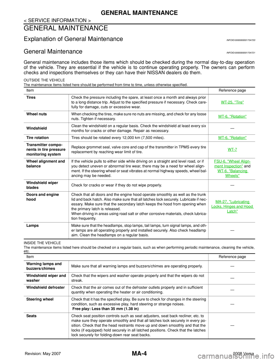
General maintenance includes those items which should be checked during the normal day-to-day operation
of the vehicle. They are essential if the vehicle is to continue operating properly. The owners can perform
checks and inspections themselves or they can have their NISSAN dealers do them.
OUTSIDE THE VEHICLE
The maintenance items listed here should be performed from time to time, unless otherwise specified.
INSIDE THE VEHICLE
The maintenance items listed here should be checked on a regular basis, such as when performing periodic maintenance, cleaning the vehicle,
etc.
ItemReference page
TiresCheck the pressure including the spare, at least once a month and always prior
to a long distance trip. Adjust to the specified pressure if necessary. Check care-
fully for damage, cuts or excessive wear.WT-25, "
Tire"
Wheel nutsWhen checking the tires, make sure no nuts are missing, and check for any loose
nuts. Tighten if necessary.WT-6, "Rotation"
WindshieldClean the windshield on a regular basis. Check the windshield at least every six
months for cracks or other damage. Repair as necessary.—
Tire rotationTires should be rotated every 12,000 km (7,500 miles).WT-6, "
Rotation"
Transmitter compo-
nents in tire pressure
monitoring systemReplace grommet seal, valve core and cap of the transmitter in TPMS every tire
replacement by reaching wear limit of tire.WT-7
Wheel alignment and
balanceIf the vehicle pulls to either side while driving on a straight and level road, or if
you detect uneven or abnormal tire wear, there may be a need for wheel align-
ment. If the steering wheel or seat vibrates at normal highway speeds, wheel bal-
ancing may be needed.FSU-6, "Wheel Align-
ment Inspection" and
WT-6, "
Balancing
Wheels"
Windshield wiper
bladesCheck for cracks or wear if they do not wipe properly. —
Doors and engine
hoodCheck that all doors and the engine hood operate smoothly as well as the trunk
lid and back hatch. Also make sure that all latches lock securely. Lubricate if nec-
essary. Make sure that the secondary latch keeps the hood from opening when
the primary latch is released.
When driving in areas using road salt or other corrosive materials, check lubrica-
tion frequently.MA-27, "
Lubricating
Locks, Hinges and Hood
Latch"
LampsMake sure that the headlamps, stop lamps, tail lamps, turn signal lamps, and oth-
er lamps are all operating properly and installed securely. Also check headlamp
aim. Clean the headlamps on a regular basis.—
ItemReference page
Warning lamps and
buzzers/chimesMake sure that all warning lamps and buzzers/chimes are operating properly. —
Windshield wiper and
washerCheck that the wipers and washer operate properly and that the wipers do not
streak.—
Windshield defrosterCheck that the air comes out of the defroster outlets properly and in sufficient
quantity when operating the heater or air conditioning.—
Steering wheelCheck that it has the specified play. Be sure to check for changes in the steering
condition, such as excessive play, hard steering or strange noises.
Free play: Less than 35 mm (1.38 in)—
SeatsCheck seat position controls such as seat adjusters, seat back recliner, etc. to
make sure they operate smoothly and that all latches lock securely in every po-
sition. Check that the head restraints move up and down smoothly and that the
locks (if equipped) hold securely in all latched positions. Check that the latches
lock securely for folding-down rear seat backs.—
Page 2283 of 2771
CHASSIS AND BODY MAINTENANCE
MA-23
< SERVICE INFORMATION >
C
D
E
F
G
H
I
J
K
MA
B
MA
N
O
P
2. Stop engine.
3. Drain A/T fluid by removing the drain plug. Reinstall the drain plug to the specified torque.
CAUTION:
Do not reuse drain plug gasket.
4. Refill the transaxle with new specified A/T fluid through the A/T fluid charging pipe. Always refill the tran-
saxle with the same volume of A/T fluid that was drained out.
5. Run engine at idle speed for 5 minutes.
6. Check A/T fluid level and condition. Refer to MA-22, "
Checking A/T Fluid" .
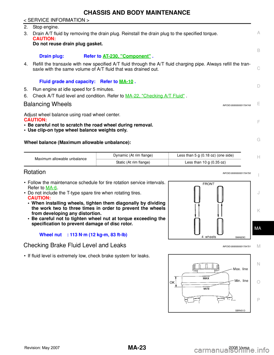
Balancing WheelsINFOID:0000000001704749
Adjust wheel balance using road wheel center.
CAUTION:
• Be careful not to scratch the road wheel during removal.
• Use clip-on type wheel balance weights only.
Wheel balance (Maximum allowable unbalance):
RotationINFOID:0000000001704750
• Follow the maintenance schedule for tire rotation service intervals.
Refer to MA-6
.
• Do not include the T-type spare tire when rotating tires.
CAUTION:
• When installing wheels, tighten them diagonally by dividing
the work two to three times in order to prevent the wheels
from developing any distortion.
• Be careful not to tighten wheel nut at torque exceeding the
specification to prevent damage of disc rotor.
Checking Brake Fluid Level and LeaksINFOID:0000000001704751
• If fluid level is extremely low, check brake system for leaks.Drain plug: Refer to AT-230, "
Component" .
Fluid grade and capacity: Refer to MA-10
.
Maximum allowable unbalanceDynamic (At rim flange) Less than 5 g (0.18 oz) (one side)
Static (At rim flange) Less than 10 g (0.35 oz)
Wheel nut : 113 N·m (12 kg-m, 83 ft-lb)SMA829C
SBR451D
Page 2561 of 2771
RSU-2
< SERVICE INFORMATION >
PRECAUTIONS
SERVICE INFORMATION
PRECAUTIONS
Precaution for Supplemental Restraint System (SRS) "AIR BAG" and "SEAT BELT
PRE-TENSIONER"
INFOID:0000000001703732
The Supplemental Restraint System such as “AIR BAG” and “SEAT BELT PRE-TENSIONER”, used along
with a front seat belt, helps to reduce the risk or severity of injury to the driver and front passenger for certain
types of collision. This system includes seat belt switch inputs and dual stage front air bag modules. The SRS
system uses the seat belt switches to determine the front air bag deployment, and may only deploy one front
air bag, depending on the severity of a collision and whether the front occupants are belted or unbelted.
Information necessary to service the system safely is included in the SRS and SB section of this Service Man-
ual.
WARNING:
• To avoid rendering the SRS inoperative, which could increase the risk of personal injury or death in
the event of a collision which would result in air bag inflation, all maintenance must be performed by
an authorized NISSAN/INFINITI dealer.
• Improper maintenance, including incorrect removal and installation of the SRS, can lead to personal
injury caused by unintentional activation of the system. For removal of Spiral Cable and Air Bag
Module, see the SRS section.
• Do not use electrical test equipment on any circuit related to the SRS unless instructed to in this
Service Manual. SRS wiring harnesses can be identified by yellow and/or orange harnesses or har-
ness connectors.
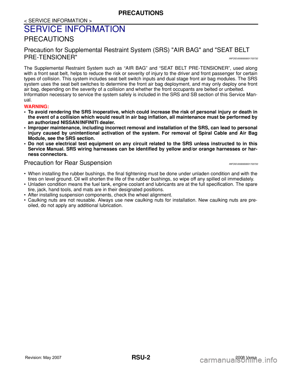
Precaution for Rear SuspensionINFOID:0000000001703733
• When installing the rubber bushings, the final tightening must be done under unladen condition and with the
tires on level ground. Oil will shorten the life of the rubber bushings, so wipe off any spilled oil immediately.
• Unladen condition means the fuel tank, engine coolant and lubricants are at the full specification. The spare
tire, jack, hand tools, and mats are in their designated positions.
• After installing suspension components, check the wheel alignment.
• Caulking nuts are not reusable. Always use new caulking nuts for installation. New caulking nuts are pre-
oiled, do not apply any additional lubrication.
Page 2564 of 2771
REAR SUSPENSION ASSEMBLY
RSU-5
< SERVICE INFORMATION >
C
D
F
G
H
I
J
K
L
MA
B
RSU
N
O
P
REAR SUSPENSION ASSEMBLY
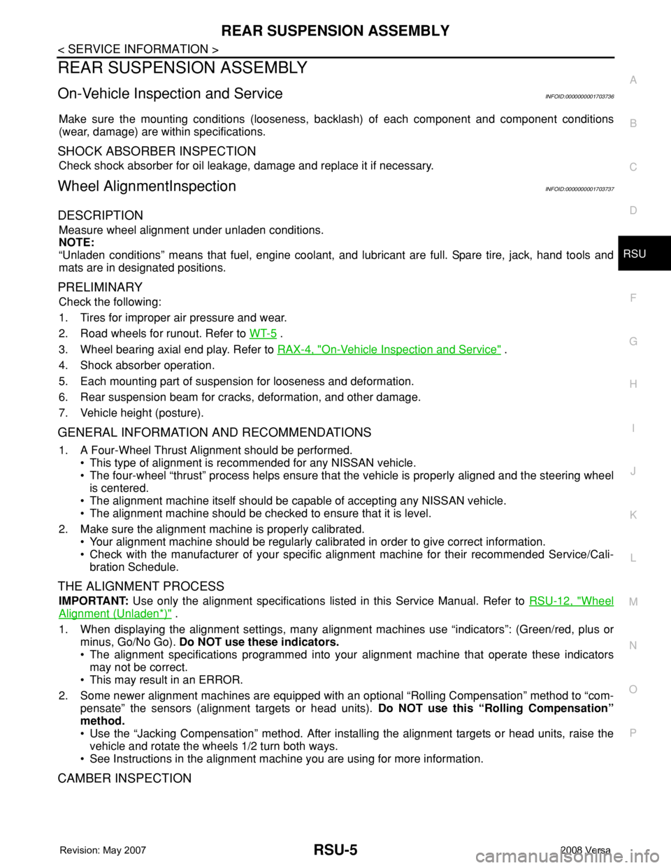
On-Vehicle Inspection and ServiceINFOID:0000000001703736
Make sure the mounting conditions (looseness, backlash) of each component and component conditions
(wear, damage) are within specifications.
SHOCK ABSORBER INSPECTION
Check shock absorber for oil leakage, damage and replace it if necessary.
Wheel AlignmentInspectionINFOID:0000000001703737
DESCRIPTION
Measure wheel alignment under unladen conditions.
NOTE:
“Unladen conditions” means that fuel, engine coolant, and lubricant are full. Spare tire, jack, hand tools and
mats are in designated positions.
PRELIMINARY
Check the following:
1. Tires for improper air pressure and wear.
2. Road wheels for runout. Refer to WT-5
.
3. Wheel bearing axial end play. Refer to RAX-4, "
On-Vehicle Inspection and Service" .
4. Shock absorber operation.
5. Each mounting part of suspension for looseness and deformation.
6. Rear suspension beam for cracks, deformation, and other damage.
7. Vehicle height (posture).
GENERAL INFORMATION AND RECOMMENDATIONS
1. A Four-Wheel Thrust Alignment should be performed.
• This type of alignment is recommended for any NISSAN vehicle.
• The four-wheel “thrust” process helps ensure that the vehicle is properly aligned and the steering wheel
is centered.
• The alignment machine itself should be capable of accepting any NISSAN vehicle.
• The alignment machine should be checked to ensure that it is level.
2. Make sure the alignment machine is properly calibrated.
• Your alignment machine should be regularly calibrated in order to give correct information.
• Check with the manufacturer of your specific alignment machine for their recommended Service/Cali-
bration Schedule.
THE ALIGNMENT PROCESS
IMPORTANT: Use only the alignment specifications listed in this Service Manual. Refer to RSU-12, "Wheel
Alignment (Unladen*)" .
1. When displaying the alignment settings, many alignment machines use “indicators”: (Green/red, plus or
minus, Go/No Go). Do NOT use these indicators.
• The alignment specifications programmed into your alignment machine that operate these indicators
may not be correct.
• This may result in an ERROR.
2. Some newer alignment machines are equipped with an optional “Rolling Compensation” method to “com-
pensate” the sensors (alignment targets or head units). Do NOT use this “Rolling Compensation”
method.
• Use the “Jacking Compensation” method. After installing the alignment targets or head units, raise the
vehicle and rotate the wheels 1/2 turn both ways.
• See Instructions in the alignment machine you are using for more information.
CAMBER INSPECTION
Page 2571 of 2771
RSU-12
< SERVICE INFORMATION >
SERVICE DATA AND SPECIFICATIONS (SDS)
SERVICE DATA AND SPECIFICATIONS (SDS)
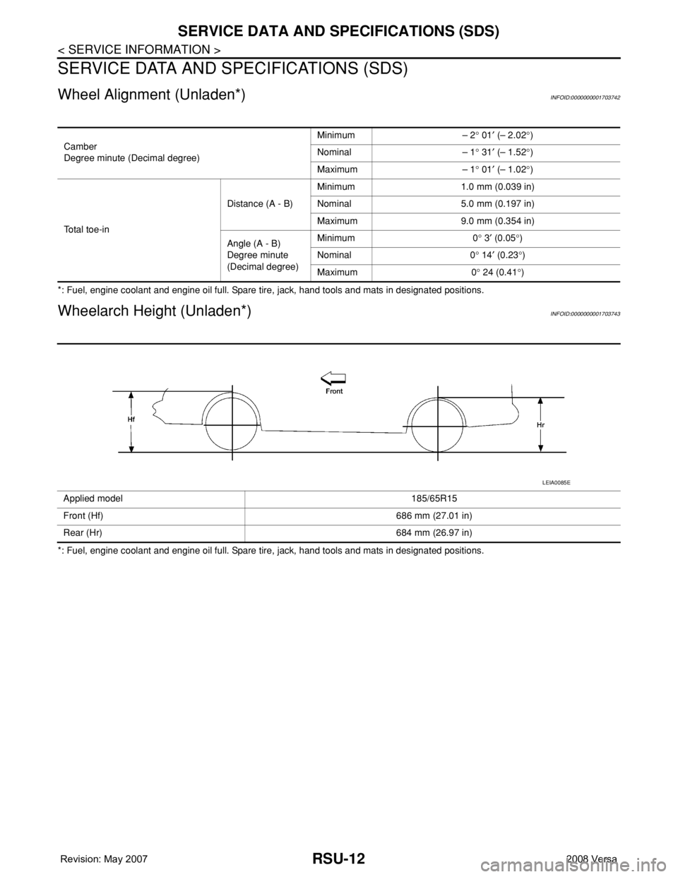
Wheel Alignment (Unladen*)INFOID:0000000001703742
*: Fuel, engine coolant and engine oil full. Spare tire, jack, hand tools and mats in designated positions.
Wheelarch Height (Unladen*)INFOID:0000000001703743
*: Fuel, engine coolant and engine oil full. Spare tire, jack, hand tools and mats in designated positions.Camber
Degree minute (Decimal degree)Minimum – 2° 01′ (– 2.02°)
Nominal – 1° 31′ (– 1.52°)
Maximum – 1° 01′ (– 1.02°)
Total toe-inDistance (A - B)Minimum 1.0 mm (0.039 in)
Nominal 5.0 mm (0.197 in)
Maximum 9.0 mm (0.354 in)
Angle (A - B)
Degree minute
(Decimal degree)Minimum 0° 3′ (0.05°)
Nominal 0° 14′ (0.23°)
Maximum 0° 24 (0.41°)
Applied model 185/65R15
Front (Hf) 686 mm (27.01 in)
Rear (Hr) 684 mm (26.97 in)
LEIA0085E
Page 2714 of 2771
WT-6
< SERVICE INFORMATION >
ROAD WHEEL TIRE ASSEMBLY
ROAD WHEEL TIRE ASSEMBLY
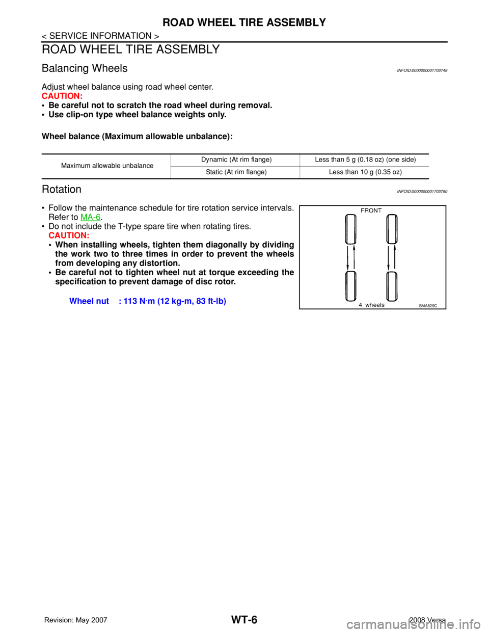
Balancing WheelsINFOID:0000000001703749
Adjust wheel balance using road wheel center.
CAUTION:
• Be careful not to scratch the road wheel during removal.
• Use clip-on type wheel balance weights only.
Wheel balance (Maximum allowable unbalance):
RotationINFOID:0000000001703750
• Follow the maintenance schedule for tire rotation service intervals.
Refer to MA-6
.
• Do not include the T-type spare tire when rotating tires.
CAUTION:
• When installing wheels, tighten them diagonally by dividing
the work two to three times in order to prevent the wheels
from developing any distortion.
• Be careful not to tighten wheel nut at torque exceeding the
specification to prevent damage of disc rotor.
Maximum allowable unbalanceDynamic (At rim flange) Less than 5 g (0.18 oz) (one side)
Static (At rim flange) Less than 10 g (0.35 oz)
Wheel nut : 113 N·m (12 kg-m, 83 ft-lb)SMA829C
Page 2733 of 2771
SERVICE DATA AND SPECIFICATIONS (SDS)
WT-25
< SERVICE INFORMATION >
C
D
F
G
H
I
J
K
L
MA
B
WT
N
O
P
SERVICE DATA AND SPECIFICATIONS (SDS)
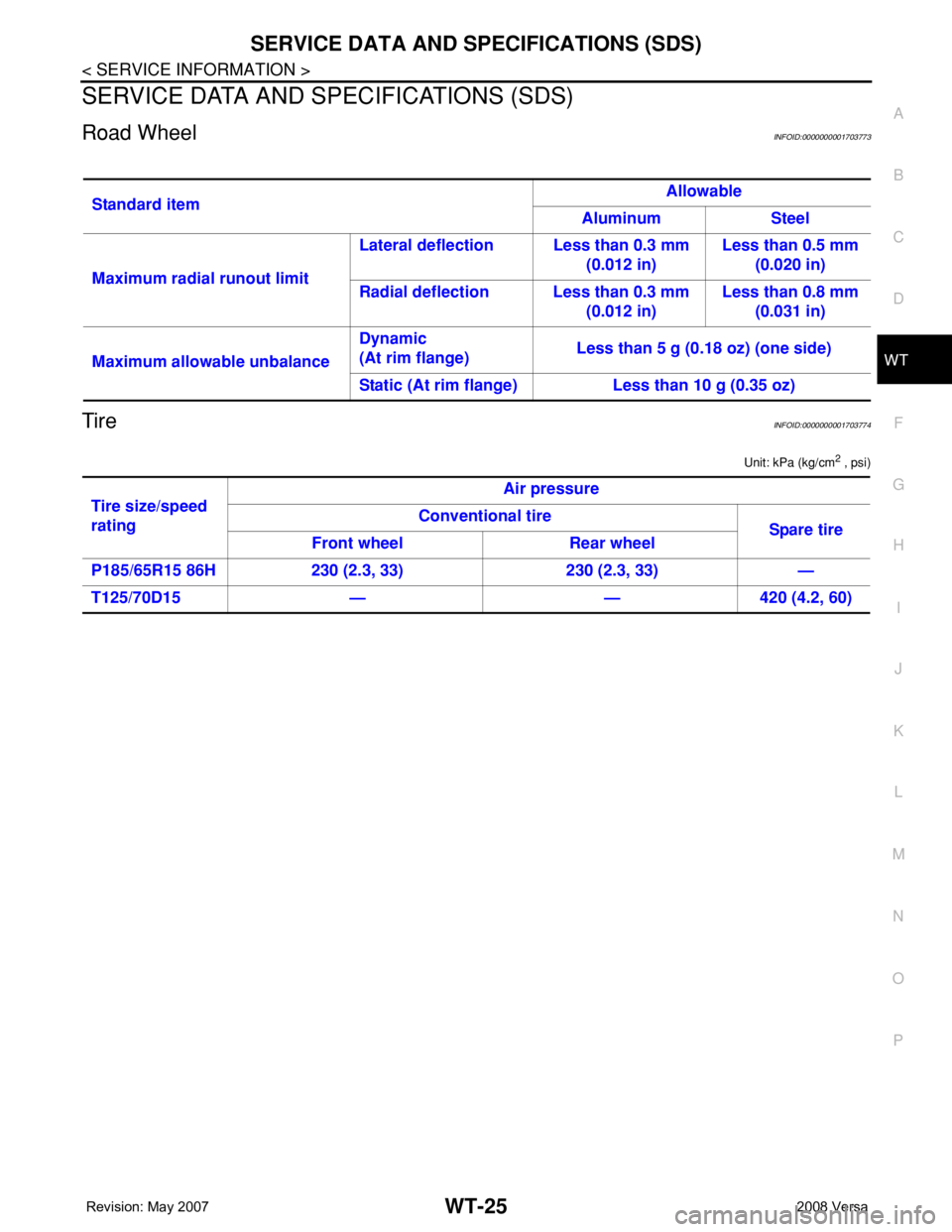
Road WheelINFOID:0000000001703773
TireINFOID:0000000001703774
Unit: kPa (kg/cm2 , psi)
Standard itemAllowable
Aluminum Steel
Maximum radial runout limitLateral deflection Less than 0.3 mm
(0.012 in)Less than 0.5 mm
(0.020 in)
Radial deflection Less than 0.3 mm
(0.012 in)Less than 0.8 mm
(0.031 in)
Maximum allowable unbalanceDynamic
(At rim flange)Less than 5 g (0.18 oz) (one side)
Static (At rim flange) Less than 10 g (0.35 oz)
Tire size/speed
ratingAir pressure
Conventional tire
Spare tire
Front wheel Rear wheel
P185/65R15 86H 230 (2.3, 33) 230 (2.3, 33) —
T125/70D15 — — 420 (4.2, 60)