2008 NISSAN TIIDA exhaust
[x] Cancel search: exhaustPage 1098 of 2771
EC-24
< SERVICE INFORMATION >
ENGINE CONTROL SYSTEM
fuel ratio (A/F) sensor 1 in the exhaust manifold to monitor whether the engine operation is rich or lean. The
ECM adjusts the injection pulse width according to the sensor voltage signal. For more information about air
fuel ratio (A/F) sensor 1, refer to EC-213
. This maintains the mixture ratio within the range of stoichiometric
(ideal air/fuel mixture).
This stage is referred to as the closed loop control condition.
Heated oxygen sensor 2 is located downstream of the three way catalyst (manifold). Even if the switching
characteristics of air fuel ratio (A/F) sensor 1 shift, the air/fuel ratio is controlled to stoichiometric by the signal
from heated oxygen sensor 2.
Open Loop Control
The open loop system condition refers to when the ECM detects any of the following conditions. Feedback
control stops in order to maintain stabilized fuel combustion.
• Deceleration and acceleration
• High-load, high-speed operation
• Malfunction of air fuel ratio (A/F) sensor 1 or its circuit
• Insufficient activation of air fuel ratio (A/F) sensor 1 at low engine coolant temperature
• High engine coolant temperature
• During warm-up
• After shifting from N to D (A/T and CVT models)
• When starting the engine
MIXTURE RATIO SELF-LEARNING CONTROL
The mixture ratio feedback control system monitors the mixture ratio signal transmitted from air fuel ratio (A/F)
sensor 1. This feedback signal is then sent to the ECM. The ECM controls the basic mixture ratio as close to
the theoretical mixture ratio as possible. However, the basic mixture ratio is not necessarily controlled as orig-
inally designed. Both manufacturing differences (i.e., mass air flow sensor hot wire) and characteristic
changes during operation (i.e., fuel injector clogging) directly affect mixture ratio.
Accordingly, the difference between the basic and theoretical mixture ratios is monitored in this system. This is
then computed in terms of “injection pulse duration” to automatically compensate for the difference between
the two ratios.
“Fuel trim” refers to the feedback compensation value compared against the basic injection duration. Fuel trim
includes short term fuel trim and long term fuel trim.
“Short term fuel trim” is the short-term fuel compensation used to maintain the mixture ratio at its theoretical
value. The signal from air fuel ratio (A/F) sensor 1 indicates whether the mixture ratio is RICH or LEAN com-
pared to the theoretical value. The signal then triggers a reduction in fuel volume if the mixture ratio is rich, and
an increase in fuel volume if it is lean.
“Long term fuel trim” is overall fuel compensation carried out long-term to compensate for continual deviation
of the short term fuel trim from the central value. Such deviation will occur due to individual engine differences,
wear over time and changes in the usage environment.
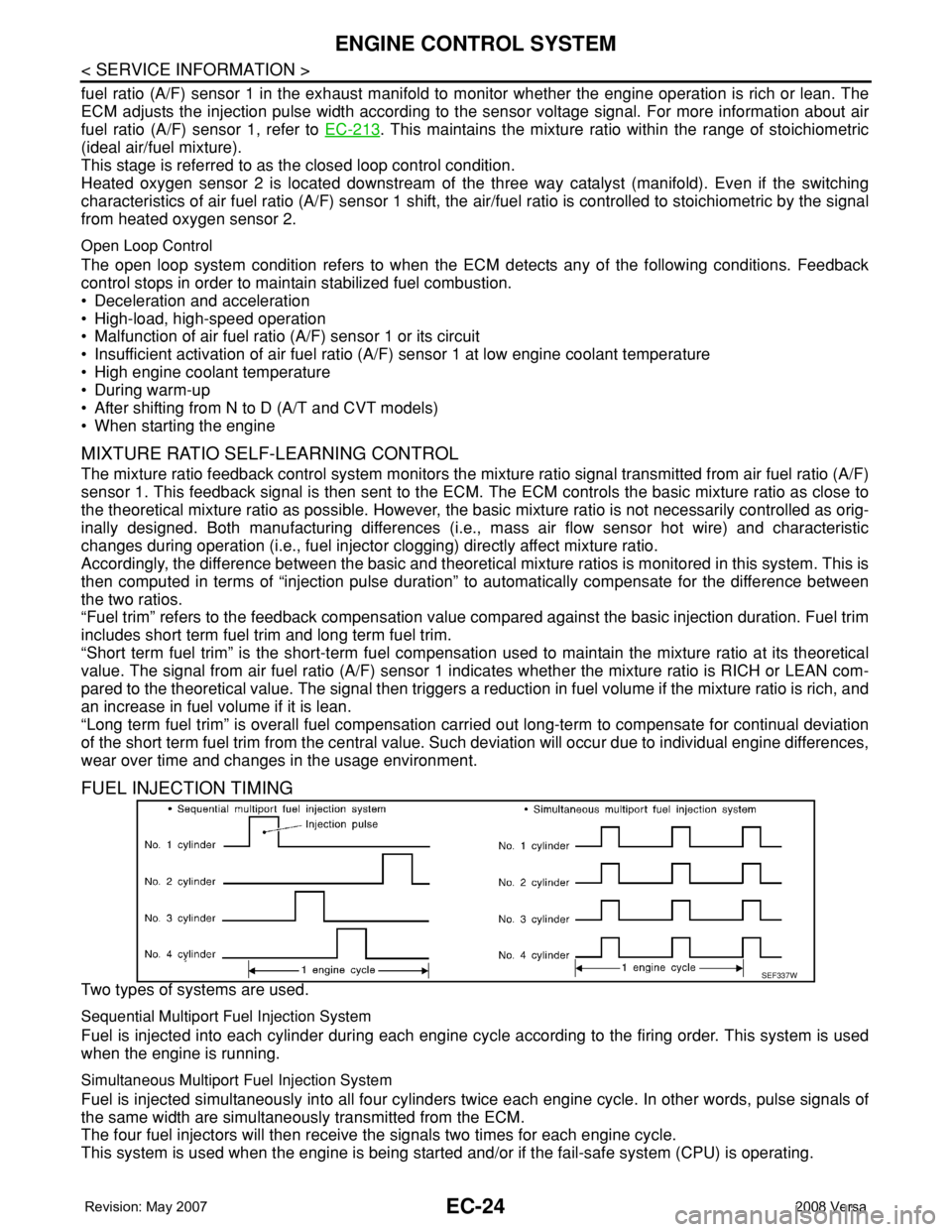
FUEL INJECTION TIMING
Two types of systems are used.
Sequential Multiport Fuel Injection System
Fuel is injected into each cylinder during each engine cycle according to the firing order. This system is used
when the engine is running.
Simultaneous Multiport Fuel Injection System
Fuel is injected simultaneously into all four cylinders twice each engine cycle. In other words, pulse signals of
the same width are simultaneously transmitted from the ECM.
The four fuel injectors will then receive the signals two times for each engine cycle.
This system is used when the engine is being started and/or if the fail-safe system (CPU) is operating.
SEF337W
Page 1138 of 2771

EC-64
< SERVICE INFORMATION >
ON BOARD DIAGNOSTIC (OBD) SYSTEM
C) without the same malfunction recurring. The “TIME” in “SELF-DIAGNOSTIC RESULTS” mode of CON-
SULT-II will count the number of times the vehicle is driven.
• The 1st trip DTC is not displayed when the self-diagnosis results in OK for the 2nd trip.
SUMMARY CHART
For details about patterns B and C under “Fuel Injection System” and “Misfire”, see "EXPLANATION FOR DRIVING PATTERNS FOR
“MISFIRE
For details about patterns A and B under “Other”, see "EXPLANATION FOR DRIVING PATTERNS FOR “MISFIRE
*1: Clear timing is at the moment OK is detected.
*2: Clear timing is when the same malfunction is detected in the 2nd trip.
RELATIONSHIP BETWEEN MIL, DTC, 1ST TRIP DTC AND DRIVING PATTERNS FOR “MISFIRE
Items Fuel Injection System Misfire Other
MIL (goes off) 3 (pattern B) 3 (pattern B) 3 (pattern B)
DTC, Freeze Frame Data (no
display)80 (pattern C) 80 (pattern C) 40 (pattern A)
1st Trip DTC (clear) 1 (pattern C), *1 1 (pattern C), *1 1 (pattern B)
1st Trip Freeze Frame Data
(clear)*1, *2 *1, *2 1 (pattern B)
Page 1139 of 2771
ON BOARD DIAGNOSTIC (OBD) SYSTEM
EC-65
< SERVICE INFORMATION >
C
D
E
F
G
H
I
J
K
L
MA
EC
N
P O
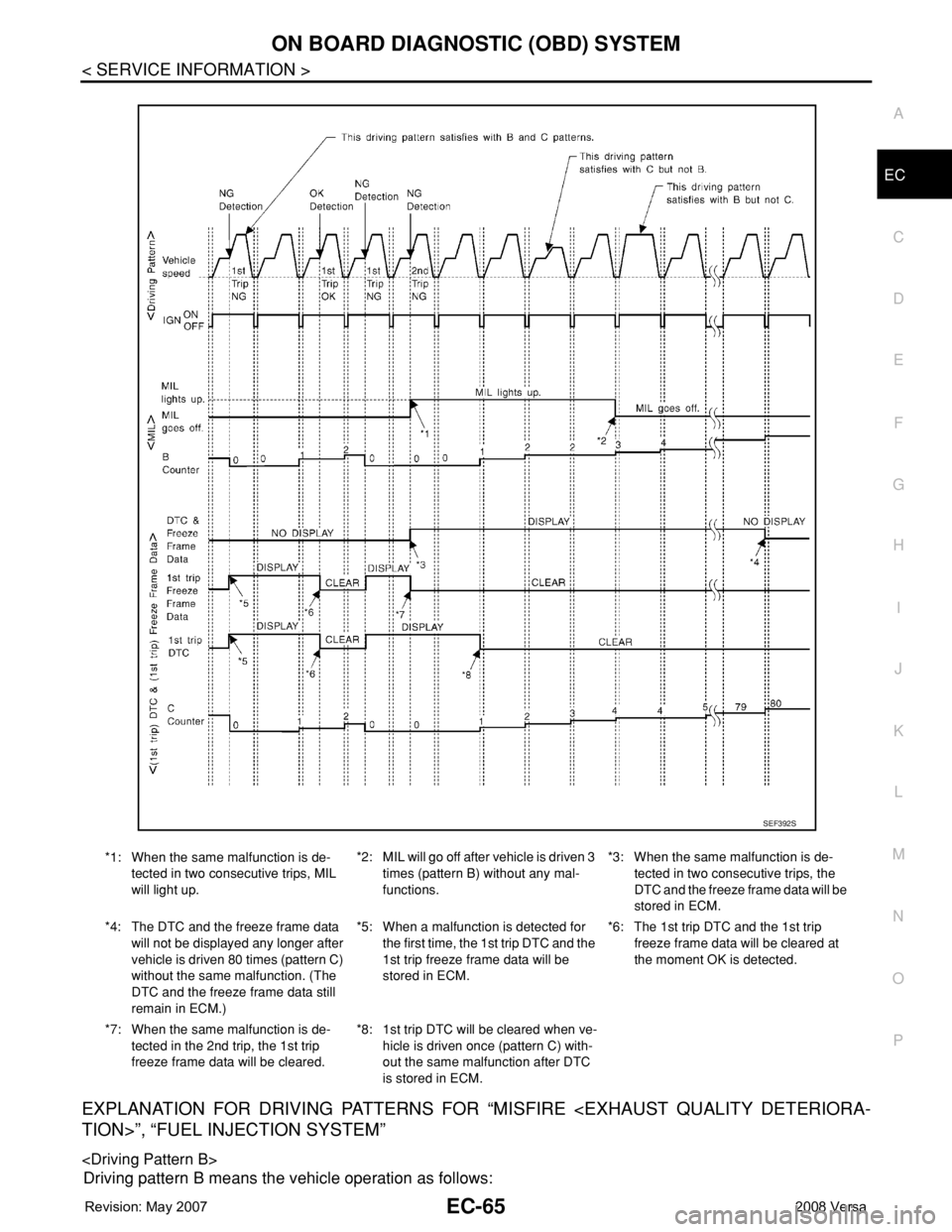
EXPLANATION FOR DRIVING PATTERNS FOR “MISFIRE
Driving pattern B means the vehicle operation as follows:
*1: When the same malfunction is de-
tected in two consecutive trips, MIL
will light up.*2: MIL will go off after vehicle is driven 3
times (pattern B) without any mal-
functions.*3: When the same malfunction is de-
tected in two consecutive trips, the
DTC and the freeze frame data will be
stored in ECM.
*4: The DTC and the freeze frame data
will not be displayed any longer after
vehicle is driven 80 times (pattern C)
without the same malfunction. (The
DTC and the freeze frame data still
remain in ECM.)*5: When a malfunction is detected for
the first time, the 1st trip DTC and the
1st trip freeze frame data will be
stored in ECM.*6: The 1st trip DTC and the 1st trip
freeze frame data will be cleared at
the moment OK is detected.
*7: When the same malfunction is de-
tected in the 2nd trip, the 1st trip
freeze frame data will be cleared.*8: 1st trip DTC will be cleared when ve-
hicle is driven once (pattern C) with-
out the same malfunction after DTC
is stored in ECM.
SEF392S
Page 1140 of 2771

EC-66
< SERVICE INFORMATION >
ON BOARD DIAGNOSTIC (OBD) SYSTEM
All components and systems should be monitored at least once by the OBD system.
• The B counter will be cleared when the malfunction is detected once regardless of the driving pattern.
• The B counter will be counted up when driving pattern B is satisfied without any malfunction.
• The MIL will go off when the B counter reaches 3. (*2 in “OBD SYSTEM OPERATION CHART”)
Driving pattern C means the vehicle operation as follows:
The following conditions should be satisfied at the same time:
Engine speed: (Engine speed in the freeze frame data) ±375 rpm
Calculated load value: (Calculated load value in the freeze frame data) x (1±0.1) [%]
Engine coolant temperature (T) condition:
• When the freeze frame data shows lower than 70°C (158°F), “T” should be lower than 70°C (158°F).
• When the freeze frame data shows higher than or equal to 70°C (158°F), “T” should be higher than or equal
to 70°C (158°F).
Example:
If the stored freeze frame data is as follows:
Engine speed: 850 rpm, Calculated load value: 30%, Engine coolant temperature: 80°C (176°F)
To be satisfied with driving pattern C, the vehicle should run under the following conditions:
Engine speed: 475 - 1,225 rpm, Calculated load value: 27 - 33%, Engine coolant temperature: more than 70°C
(158°F)
• The C counter will be cleared when the malfunction is detected regardless of vehicle conditions above.
• The C counter will be counted up when vehicle conditions above is satisfied without the same malfunction.
• The DTC will not be displayed after C counter reaches 80.
• The 1st trip DTC will be cleared when C counter is counted once without the same malfunction after DTC is
stored in ECM.
RELATIONSHIP BETWEEN MIL, DTC, 1ST TRIP DTC AND DRIVING PATTERNS EXCEPT FOR
“MISFIRE
Page 1141 of 2771
ON BOARD DIAGNOSTIC (OBD) SYSTEM
EC-67
< SERVICE INFORMATION >
C
D
E
F
G
H
I
J
K
L
MA
EC
N
P O
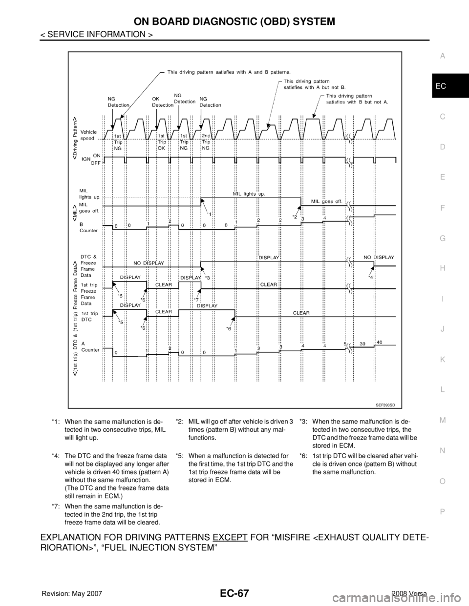
EXPLANATION FOR DRIVING PATTERNS EXCEPT FOR “MISFIRE
*1: When the same malfunction is de-
tected in two consecutive trips, MIL
will light up.*2: MIL will go off after vehicle is driven 3
times (pattern B) without any mal-
functions.*3: When the same malfunction is de-
tected in two consecutive trips, the
DTC and the freeze frame data will be
stored in ECM.
*4: The DTC and the freeze frame data
will not be displayed any longer after
vehicle is driven 40 times (pattern A)
without the same malfunction.
(The DTC and the freeze frame data
still remain in ECM.)*5: When a malfunction is detected for
the first time, the 1st trip DTC and the
1st trip freeze frame data will be
stored in ECM.*6: 1st trip DTC will be cleared after vehi-
cle is driven once (pattern B) without
the same malfunction.
*7: When the same malfunction is de-
tected in the 2nd trip, the 1st trip
freeze frame data will be cleared.
SEF393SD
Page 1165 of 2771
TROUBLE DIAGNOSIS
EC-91
< SERVICE INFORMATION >
C
D
E
F
G
H
I
J
K
L
MA
EC
N
P O
Air Air duct
55555 5EM-16
Air cleanerEM-16
Air leakage from air duct
(Mass air flow sensor — electric
throttle control actuator)
5555EM-16
Electric throttle control actuatorEM-18
Air leakage from intake manifold/
Collector/GasketEM-18
Cranking Battery
111111
11SC-4
Generator circuitSC-20
Starter circuit 3SC-8
Signal plate 6EM-76
Park/neutral position (PNP)
switch4MT-12, AT-
86 or
CVT-65
Engine Cylinder head
55555 55 5EM-62
Cylinder head gasket 4 3
Cylinder block
66666 66 64
EM-76
Piston
Piston ring
Connecting rod
Bearing
Crankshaft
Va l v e
mecha-
nismTiming chain
55555 55 5EM-37
CamshaftEM-47
Intake valve timing controlEM-37
Intake valve
3EM-62
Exhaust valve
Exhaust Exhaust manifold/Tube/Muffler/
Gasket
55555 55 5EM-21
, EX-
4Three way catalyst
Lubrica-
tionOil pan/Oil strainer/Oil pump/Oil
filter/Oil gallery
55555 55 5EM-24
, LU-
9
Oil level (Low)/Filthy oilLU-6
SYMPTOM
Reference
page
HARD/NO START/RESTART (EXCP. HA)
ENGINE STALL
HESITATION/SURGING/FLAT SPOT
SPARK KNOCK/DETONATION
LACK OF POWER/POOR ACCELERATION
HIGH IDLE/LOW IDLE
ROUGH IDLE/HUNTING
IDLING VIBRATION
SLOW/NO RETURN TO IDLE
OVERHEATS/WATER TEMPERATURE HIGH
EXCESSIVE FUEL CONSUMPTION
EXCESSIVE OIL CONSUMPTION
BATTERY DEAD (UNDER CHARGE)
Warranty symptom code AA AB AC AD AE AF AG AH AJ AK AL AM HA
Page 1229 of 2771
DTC P0031, P0032 A/F SENSOR 1 HEATER
EC-155
< SERVICE INFORMATION >
C
D
E
F
G
H
I
J
K
L
MA
EC
N
P O
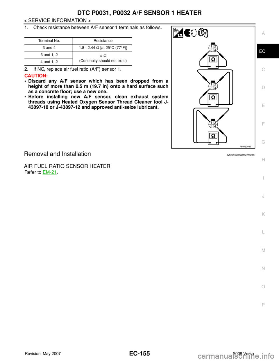
1. Check resistance between A/F sensor 1 terminals as follows.
2. If NG, replace air fuel ratio (A/F) sensor 1.
CAUTION:
• Discard any A/F sensor which has been dropped from a
height of more than 0.5 m (19.7 in) onto a hard surface such
as a concrete floor; use a new one.
• Before installing new A/F sensor, clean exhaust system
threads using Heated Oxygen Sensor Thread Cleaner tool J-
43897-18 or J-43897-12 and approved anti-seize lubricant.
Removal and InstallationINFOID:0000000001702631
AIR FUEL RATIO SENSOR HEATER
Refer to EM-21.
Terminal No. Resistance
3 and 4 1.8 - 2.44 Ω [at 25°C (77°F)]
3 and 1, 2
∞ Ω
(Continuity should not exist)
4 and 1, 2
PBIB3309E
Page 1235 of 2771
DTC P0037, P0038 HO2S2 HEATER
EC-161
< SERVICE INFORMATION >
C
D
E
F
G
H
I
J
K
L
MA
EC
N
P O
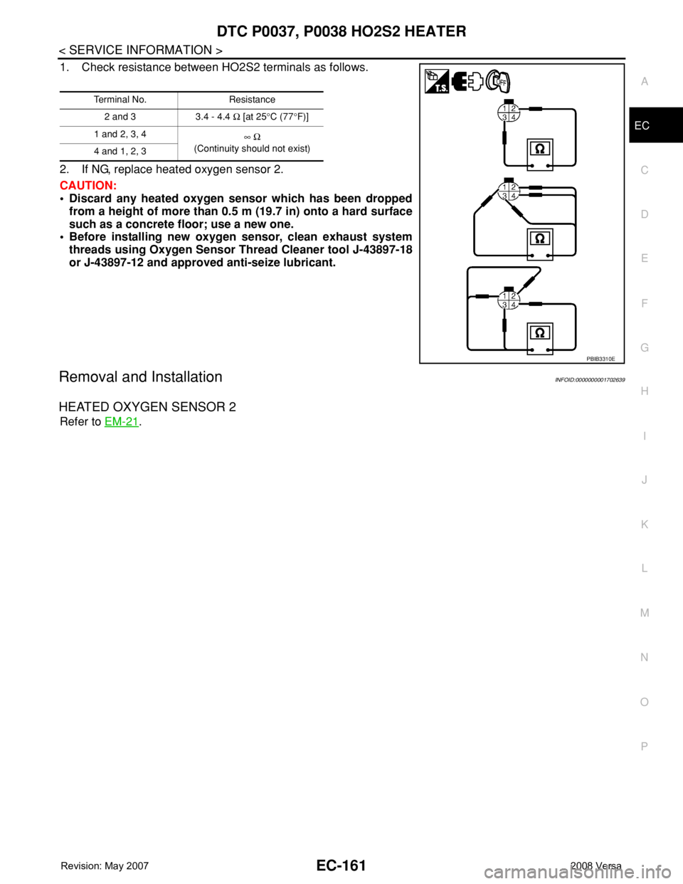
1. Check resistance between HO2S2 terminals as follows.
2. If NG, replace heated oxygen sensor 2.
CAUTION:
• Discard any heated oxygen sensor which has been dropped
from a height of more than 0.5 m (19.7 in) onto a hard surface
such as a concrete floor; use a new one.
• Before installing new oxygen sensor, clean exhaust system
threads using Oxygen Sensor Thread Cleaner tool J-43897-18
or J-43897-12 and approved anti-seize lubricant.
Removal and InstallationINFOID:0000000001702639
HEATED OXYGEN SENSOR 2
Refer to EM-21.
Terminal No. Resistance
2 and 3 3.4 - 4.4 Ω [at 25°C (77°F)]
1 and 2, 3, 4
∞ Ω
(Continuity should not exist)
4 and 1, 2, 3
PBIB3310E