2008 NISSAN TIIDA coolant reservoir
[x] Cancel search: coolant reservoirPage 1488 of 2771

EC-414
< SERVICE INFORMATION >
DTC P1217 ENGINE OVER TEMPERATURE
Never remove the radiator cap when the engine is hot. Serious burns could be caused by high pres-
sure fluid escaping from the reservoir tank or the radiator.
Wrap a thick cloth around cap. Carefully remove the cap by turning it a quarter turn to allow built-up
pressure to escape. Then turn the cap all the way off.
WITH CONSULT-II
1. Check the coolant level in the reservoir tank and radiator.
Allow engine to cool before checking coolant level.
If the coolant level in the reservoir tank and/or radiator is below
the proper range, skip the following steps and go to EC-417,
"Diagnosis Procedure" or EC-417, "Diagnosis Procedure".
2. Confirm whether customer filled the coolant or not. If customer
filled the coolant, skip the following steps and go to EC-417,
"Diagnosis Procedure" or EC-417, "Diagnosis Procedure".
3. Turn ignition switch ON.
4. Perform “COOLING FAN” in “ACTIVE TEST” mode with CON-
SULT-II.
5. If the results are NG, go to EC-417, "
Diagnosis Procedure" or
EC-417, "
Diagnosis Procedure".
WITH GST
Models with A/C
1. Check the coolant level in the reservoir tank and radiator.
Allow engine to cool before checking coolant level.
If the coolant level in the reservoir tank and/or radiator is below
the proper range, skip the following steps and go to EC-417,
"Diagnosis Procedure".
2. Confirm whether customer filled the coolant or not. If customer
filled the coolant, skip the following steps and go to EC-417,
"Diagnosis Procedure".
3. Start engine.
CAUTION:
Be careful not to overheat engine.
4. Set temperature control switch to full cold position.
5. Turn air conditioner switch ON.
6. Turn blower fan switch ON.
7. Run engine at idle for a few minutes with air conditioner operating.
CAUTION:
Be careful not to overheat engine.
SEF621W
SEF646X
SEF621W
Page 1489 of 2771
DTC P1217 ENGINE OVER TEMPERATURE
EC-415
< SERVICE INFORMATION >
C
D
E
F
G
H
I
J
K
L
MA
EC
N
P O
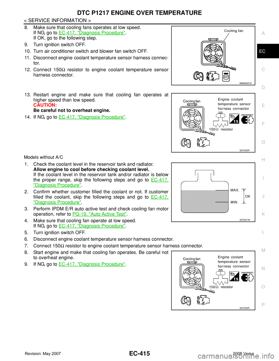
8. Make sure that cooling fans operates at low speed.
If NG, go to EC-417, "
Diagnosis Procedure".
If OK, go to the following step.
9. Turn ignition switch OFF.
10. Turn air conditioner switch and blower fan switch OFF.
11. Disconnect engine coolant temperature sensor harness connec-
tor.
12. Connect 150Ω resistor to engine coolant temperature sensor
harness connector.
13. Restart engine and make sure that cooling fan operates at
higher speed than low speed.
CAUTION:
Be careful not to overheat engine.
14. If NG, go to EC-417, "
Diagnosis Procedure".
Models without A/C
1. Check the coolant level in the reservoir tank and radiator.
Allow engine to cool before checking coolant level.
If the coolant level in the reservoir tank and/or radiator is below
the proper range, skip the following steps and go to EC-417,
"Diagnosis Procedure".
2. Confirm whether customer filled the coolant or not. If customer
filled the coolant, skip the following steps and go to EC-417,
"Diagnosis Procedure".
3. Perform IPDM E/R auto active test and check cooling fan motor
operation, refer to PG-19, "
Auto Active Test".
4. Make sure that cooling fan operate at low speed.
If NG, go to EC-417, "
Diagnosis Procedure".
5. Turn ignition switch OFF.
6. Disconnect engine coolant temperature sensor harness connector.
7. Connect 150Ω resistor to engine coolant temperature sensor harness connector.
8. Start engine and make that cooling fan operates. Be careful not
to overheat engine.
9. If NG, go to EC-417, "
Diagnosis Procedure".
MBIB0651E
SEF023R
SEF621W
SEF023R
Page 1498 of 2771

EC-424
< SERVICE INFORMATION >
DTC P1217 ENGINE OVER TEMPERATURE
OK >> GO TO 6.
NG >> Replace cooling fan motor.
6.CHECK INTERMITTENT INCIDENT
Perform EC-136
.
OK or NG
OK >> Replace IPDM E/R. Refer to PG-26, "Removal and Installation of IPDM E/R".
NG >> Repair or replace harness or connector.
Main 13 Causes of OverheatingINFOID:0000000001702935
*1: Turn the ignition switch ON.
*2: Engine running at 3,000 rpm for 10 minutes.
*3: Drive at 90 km/h (55 MPH) for 30 minutes and then let idle for 10 minutes.
*4: After 60 minutes of cool down time.
For more information, refer to CO-5
.
Component InspectionINFOID:0000000001702936
COOLING FAN MOTOR
Model with A/C
Engine Step Inspection item Equipment Standard Reference page
OFF 1 • Blocked radiator
• Blocked condenser
• Blocked radiator grille
• Blocked bumper• Visual No blocking —
2 • Coolant mixture • Coolant tester 50 - 50% coolant mixture See MA-11, "
Anti-freeze
Coolant Mixture Ratio".
3 • Coolant level • Visual Coolant up to MAX level in
reservoir tank and radiator
filler neckSee CO-8, "
Inspection".
4 • Radiator cap • Pressure tester 59 - 98 kPa
(0.6 - 1.0 kg/cm
2, 9 - 14
psi) (Limit)See CO-13, "
Checking
Radiator Cap".
ON*
25 • Coolant leaks • Visual No leaks See CO-8, "Inspection".
ON*
26 • Thermostat • Touch the upper and
lower radiator hosesBoth hoses should be hot See CO-17, and CO-11
ON*17 • Cooling fan • CONSULT-II Operating See trouble diagnosis for
DTC P1217 (EC-417, "
Di-
agnosis Procedure").
OFF 8 • Combustion gas leak • Color checker chemical
tester 4 Gas analyzerNegative —
ON*
39 • Coolant temperature
gauge• Visual Gauge less than 3/4 when
driving—
• Coolant overflow to res-
ervoir tank• Visual No overflow during driving
and idlingSee CO-8, "
Changing En-
gine Coolant".
OFF*
410 • Coolant return from res-
ervoir tank to radiator• Visual Should be initial level in
reservoir tankSee CO-8, "Inspection".
OFF 11 • Water control valve• Remove and inspect
the valveWithin the specified valueSee CO-19, "
Removal
and Installation"
OFF 12 • Cylinder head • Straight gauge feeler
gauge0.1 mm (0.004 in) Maxi-
mum distortion (warping)See EM-62.
13 • Cylinder block and pis-
tons• Visual No scuffing on cylinder
walls or pistonSee EM-76
.
Page 2265 of 2771

GENERAL MAINTENANCE
MA-5
< SERVICE INFORMATION >
C
D
E
F
G
H
I
J
K
MA
B
MA
N
O
P
UNDER THE HOOD AND VEHICLE
The maintenance items listed here should be checked periodically (e.g. each time you check the engine oil or refuel).
Seat belts
Check that all parts of the seat belt system (e.g. buckles, anchors, adjusters and
retractors) operate properly and smoothly and are installed securely. Check the
belt webbing for cuts, fraying, wear or damage.MA-27, "Checking Seat
Belts, Buckles, Retrac-
tors, Anchors and Adjust-
ers"
Accelerator pedalCheck the pedal for smooth operation and make sure the pedal does not catch
or require uneven effort. Keep the floor mats away from the pedal.—
Clutch pedalMake sure the pedal operates smoothly and check that it has the proper free play.MA-21
BrakesCheck that the brake does not pull the vehicle to one side when applied. —
Brake pedal and
boosterCheck the pedal for smooth operation and make sure it has the proper distance
under it when depressed fully. Check the brake booster function. Be sure to keep
floor mats away from the pedal.BR-5, "
Inspection and
Adjustment" and BR-18,
"On Board Inspection"
Parking brakeCheck that the lever has the proper travel and make sure that the vehicle is held
securely on a fairly steep hill when only the parking brake is applied.PB-4, "On-Vehicle Ser-
vice"
Automatic transaxle
“Park” mechanismCheck that the lock release button on the selector lever operates properly and
smoothly. On a fairly steep hill check that the vehicle is held securely with the se-
lector lever in the “P” position without applying any brakes.—
CVT P (Park) position
mechanismOn a fairly steep hill check that the vehicle is held securely with the selector lever
in the “P” position without applying any brakes.— ItemReference page
ItemReference page
Windshield wash-
er fluidCheck that there is adequate fluid in the tank. —
Engine coolant
levelCheck the coolant level when the engine is cold.CO-8, "
Inspection"
A/C condenser,
radiator and hos-
esCheck the front of the condenser and radiator and clean off any dirt, insects, leaves,
etc., that may have accumulated. Make sure the radiator hoses have no cracks, de-
formation, deterioration or loose connections.—
Brake and clutch
fluid levelsMake sure that the brake and clutch fluid levels are between the “MAX” and “MIN”
lines on the reservoirs.BR-8, "
On Board Inspec-
tion" and MA-21, "Checking
Clutch Fluid Level and
Leaks"
BatteryCheck the fluid level in each cell. It should be between the “MAX” and “MIN” lines.
Vehicles operated in high temperatures or under severe conditions require frequent
checks of the battery fluid level.—
Engine drive beltsMake sure that no belt is frayed, worn, cracked or oily.MA-12
Engine oil levelCheck the level on the dipstick after parking the vehicle on a level spot and turning
off the engine.LU-6, "Inspection"
Automatic tran-
saxle fluid levelCheck the level on the dipstick after putting the selector lever in “P” with the engine
idling.MA-19 and MA-22
Exhaust systemMake sure there are no loose supports, cracks or holes. If the sound of the exhaust
seems unusual or there is a smell of exhaust fumes, immediately locate the trouble
and correct it.MA-19
UnderbodyThe underbody is frequently exposed to corrosive substances such as those used
on icy roads or to control dust. It is very important to remove these substances, oth-
erwise rust will form on the floor pan, frame, fuel lines and around the exhaust sys-
tem. At the end of winter, the underbody should be thoroughly flushed with plain
water, being careful to clean those areas where mud and dirt can easily accumu-
late.—
Fluid leaksCheck under the vehicle for fuel, oil, water or other fluid leaks after the vehicle has
been parked for a while. Water dripping from the air conditioner after use is normal.
If you should notice any leaks or gasoline fumes are evident, check for the cause
and correct it immediately.—
Page 2270 of 2771

MA-10
< SERVICE INFORMATION >
RECOMMENDED FLUIDS AND LUBRICANTS
RECOMMENDED FLUIDS AND LUBRICANTS
Fluids and LubricantsINFOID:0000000001704725
*1: For further details, see “Engine Oil Recommendation”.
*2: DEXRON
TM III / MERCONTM , or equivalent may also be used. Outside the continental United States and Alaska contact a NISSAN
dealership for more information regarding suitable fluids, including recommended brand(s) of DEXRONTM III / MERCONTM Automatic
Transmission Fluid.
*3: Using transaxle fluid other than Genuine NISSAN CVT Fluid NS-2 will damage the CVT, which is not covered by the NISSAN
new vehicle limited warranty.
*4: Available in mainland U.S.A. through your NISSAN dealer.
*5: For further details, see “Air conditioner specification label”.
SAE Viscosity NumberINFOID:0000000001704726
NISSAN recommends the use of an energy conserving oil in order to improve fuel economy.
Select only engine oils that meet the American Petroleum Institute (API) certification and International Lubrica-
tion Standardization and Approval Committee (ILSAC) certification and SAE viscosity standard. These oils
have the API certification mark on the front of the container. Oils which do not have the specified quality label
should not be used as they could cause engine damage.
DescriptionCapacity (Approximate)
Recommended Fluids/Lubricants
Liter US measure Imp measure
Fuel 52.0 13 3/4 gal 11 1/2 galUnleaded gasoline with an octane rating of
at least 87 AKI (RON 91)
Engine oil
Drain and refillWith oil filter
change3.9 4 1/8 qt 3 3/8 qt
• Engine oil with API Certification Mark *1
• Viscosity SAE 5W-30 Without oil filter
change3.7 3 7/8 qt 3 1/4 qt
Dry engine (engine overhaul) 4.9 5 1/8 qt 4 3/8 qt
Cooling system
(with reservoir at max level)6.8 7 1/4 qt 6 qtGenuine NISSAN Long Life Anti-freeze
Coolant or equivalent
Manual transaxle fluid (MTF) 2.0 4 1/4 pt 3 1/2 ptEFF XT4447 M+ 75W-80 or API GL-4, Vis-
cosity SAE 75W-80
Automatic transaxle fluid (ATF) 7.9 8 3/8 qt 7 qtGenuine NISSAN Matic “D” ATF (Continen-
tal U.S. and Alaska) or Canada NISSAN
Automatic Transmission Fluid *2
CVT fluid 8.3 8 3/4 qt 7 1/4 qt Genuine NISSAN CVT Fluid NS-2 *3
Brake and clutch fluid — — —Genuine NISSAN Super Heavy Duty Brake
Fluid*4 or equivalent DOT 3 (US FMVSS
No. 116)
Multi-purpose grease — — — NLGI No. 2 (Lithium soap base)
Windshield washer fluid 4.5 4 3/4 qt 4 qtGenuine NISSAN Windshield Washer Con-
centrate Cleaner & Anti-Freeze or equiva-
lent
Air conditioning system refrigerant 0.45 ± 0.05 kg 0.99 ± 0.11 lb 0.99 ± 0.11 lb HFC-134a (R-134a) *5
Air conditioning
system oilTyp e 1
120 m4.1 fl oz 4.2 fl ozNISSAN A/C System Lubricant Type R or
equivalent *5
Typ e 2
100 m3.4 fl oz 3.5 fl ozNISSAN A/C System Lubricant Type S or
equivalent *5
Page 2273 of 2771

ENGINE MAINTENANCE
MA-13
< SERVICE INFORMATION >
C
D
E
F
G
H
I
J
K
MA
B
MA
N
O
P
2. Remove reservoir tank as necessary, and drain engine coolant and clean reservoir tank before installing.
Refer to CO-11
.
3. Check drained engine coolant for contaminants such as rust, corrosion or discoloration.
If contaminated, flush the engine cooling system. Refer to "FLUSHING COOLING SYSTEM" .
REFILLING ENGINE COOLANT
1. Install reservoir tank if removed. Refer to CO-11 .
2. Install radiator drain plug.
•If water drain plug on cylinder block is removed, close and tighten it. Refer to EM-76
.
CAUTION:
Be sure to clean radiator drain plug and install with new O-ring. Refer to CO-11, "
Component" .
3. Make sure that each hose clamp has been firmly tightened.
4. Remove air duct assembly. Refer to EM-16
.
5. Disconnect heater hose (1) at position ( ) as shown.
• Front
• Enhance heater hose as high as possible.
6. Fill radiator and reservoir tank to specified level.
•Pour engine coolant through engine coolant filler neck
slowly of less than 2 (2 1/8 US qt, 1-3/4 lmp qt) a minute
to allow air in system to escape.
•Use NISSAN Genuine Engine Coolant or equivalent mixed
with water (distilled or demineralized). Fill cooling system
to specification. Refer to MA-10
.
• When engine coolant overflows disconnected heater hose,
connect heater hose, and continue filling the engine coolant, if
heater hose is disconnected.
7. Install radiator cap.
8. Install air duct assembly. Refer to EM-16
.
9. Warm up until opening thermostat. Standard for warming-up time is approximately 10 minutes at 3,000
rpm.
• Make sure thermostat opening condition by touching radiator hose (lower) to see a flow of warm water.
CAUTION:
Watch water temperature gauge so as not to overheat the engine.
10. Stop engine and cool down to less than approximately 50°C (122°F).
• Cool down using fan to reduce the time.
• If necessary, refill radiator up to filler neck with engine coolant.
11. Refill reservoir tank to “MAX” level line with engine coolant.
12. Repeat steps 6 through 10 two or more times with radiator cap installed until engine coolant level no
longer drops.
13. Check cooling system for leaks with engine running.
14. Warm up engine, and check for sound of engine coolant flow while running engine from idle up to 3,000
rpm with heater temperature controller set at several position between “COOL” and “WARM”.
• Sound may be noticeable at heater unit.
15. Repeat step 14 three times.
16. If sound is heard, bleed air from cooling system by repeating steps 6 through 10 until engine coolant level
no longer drops.
FLUSHING COOLING SYSTEM
PBIC3802E
SMA182B
Page 2274 of 2771

MA-14
< SERVICE INFORMATION >
ENGINE MAINTENANCE
1. Install reservoir tank if removed. Refer to CO-11 .
2. Install radiator drain plug.
•If water drain plug on cylinder block is removed, close and tighten it. Refer to EM-76
.
CAUTION:
Be sure to clean radiator drain plug and install with new O-ring. Refer to CO-11, "
Component" .
3. Fill radiator and reservoir tank with water and reinstall radiator cap.
4. Run engine and warm it up to normal operating temperature.
5. Rev engine two or three times under no-load.
6. Stop engine and wait until it cools down.
7. Drain water from the cooling system. Refer to "DRAINING ENGINE COOLANT" .
8. Repeat steps 1 through 7 until clear water begins to drain from radiator.
InspectionINFOID:0000000001704732
LEVEL CHECK
• Check if the reservoir tank engine coolant level is within the “MIN”
to “MAX” range when engine is cool.
• Adjust the engine coolant level as necessary.
CHECKING COOLING SYSTEM FOR LEAKS
To check for leaks, apply pressure to the cooling system using Tool.
WARNING:
Never remove the radiator cap when the engine is hot. Serious
burns could occur from high pressure coolant escaping from
the radiator.
CAUTION:
Higher pressure than specified may cause radiator damage.
Checking Fuel LineINFOID:0000000001704733
Inspect fuel lines, fuel filler cap and fuel tank for improper attach-
ment, leaks, cracks, damage, loose connections, chafing or deterio-
ration.
If necessary, repair or replace damaged parts.
Changing Air Cleaner FilterINFOID:0000000001704734
REMOVAL
SMA412B
Tool number : EG17650301 (J-33984-A)
Testing pressure
: 157 kPa (1.6 kg/cm
2 , 23 psi)
WBIA0568E
SMA803A