2008 NISSAN TIIDA brakes
[x] Cancel search: brakesPage 303 of 2771
REPAIR FOR COMPONENT PARTS
AT-291
< SERVICE INFORMATION >
D
E
F
G
H
I
J
K
L
MA
B
AT
N
O
P
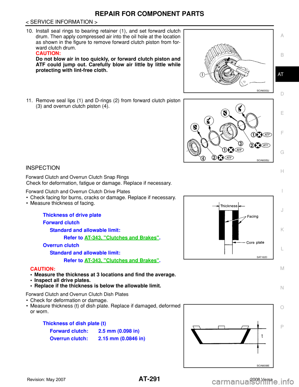
10. Install seal rings to bearing retainer (1), and set forward clutch
drum. Then apply compressed air into the oil hole at the location
as shown in the figure to remove forward clutch piston from for-
ward clutch drum.
CAUTION:
Do not blow air in too quickly, or forward clutch piston and
ATF could jump out. Carefully blow air little by little while
protecting with lint-free cloth.
11. Remove seal lips (1) and D-rings (2) from forward clutch piston
(3) and overrun clutch piston (4).
INSPECTION
Forward Clutch and Overrun Clutch Snap Rings
Check for deformation, fatigue or damage. Replace if necessary.
Forward Clutch and Overrun Clutch Drive Plates
• Check facing for burns, cracks or damage. Replace if necessary.
• Measure thickness of facing.
CAUTION:
• Measure the thickness at 3 locations and find the average.
• Inspect all drive plates.
• Replace if the thickness is below the allowable limit.
Forward Clutch and Overrun Clutch Dish Plates
• Check for deformation or damage.
• Measure thickness (t) of dish plate. Replace if damaged, deformed
or worn.
SCIA6003J
SCIA6005J
Thickness of drive plate
Forward clutch
Standard and allowable limit:
Refer to AT-343, "
Clutches and Brakes".
Overrun clutch
Standard and allowable limit:
Refer to AT-343, "
Clutches and Brakes".SAT162D
Thickness of dish plate (t)
Forward clutch: 2.5 mm (0.098 in)
Overrun clutch: 2.15 mm (0.0846 in)
SCIA8008E
Page 306 of 2771
AT-294
< SERVICE INFORMATION >
REPAIR FOR COMPONENT PARTS
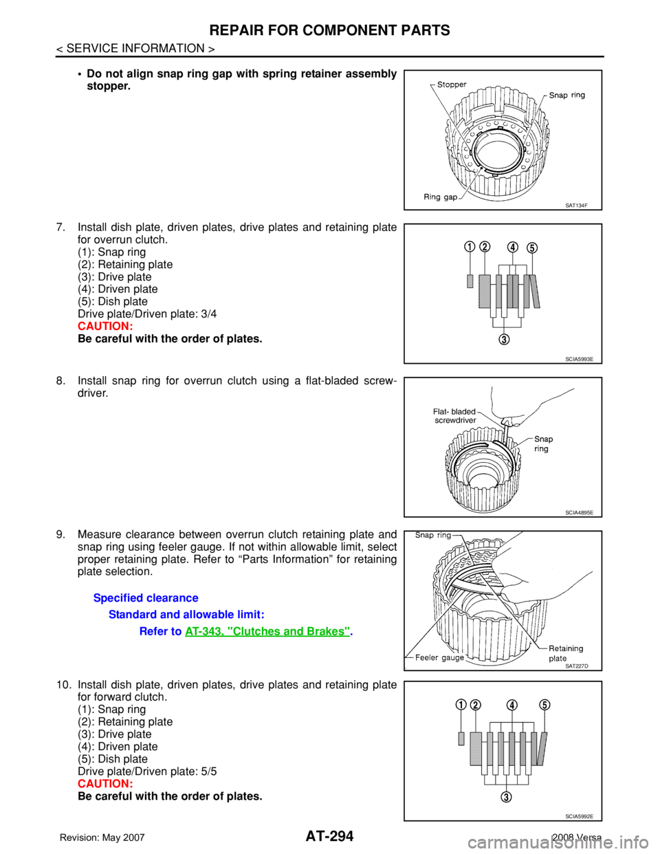
• Do not align snap ring gap with spring retainer assembly
stopper.
7. Install dish plate, driven plates, drive plates and retaining plate
for overrun clutch.
(1): Snap ring
(2): Retaining plate
(3): Drive plate
(4): Driven plate
(5): Dish plate
Drive plate/Driven plate: 3/4
CAUTION:
Be careful with the order of plates.
8. Install snap ring for overrun clutch using a flat-bladed screw-
driver.
9. Measure clearance between overrun clutch retaining plate and
snap ring using feeler gauge. If not within allowable limit, select
proper retaining plate. Refer to “Parts Information” for retaining
plate selection.
10. Install dish plate, driven plates, drive plates and retaining plate
for forward clutch.
(1): Snap ring
(2): Retaining plate
(3): Drive plate
(4): Driven plate
(5): Dish plate
Drive plate/Driven plate: 5/5
CAUTION:
Be careful with the order of plates.
SAT134F
SCIA5993E
SCIA4895E
Specified clearance
Standard and allowable limit:
Refer to AT-343, "
Clutches and Brakes".
SAT227D
SCIA5992E
Page 307 of 2771
REPAIR FOR COMPONENT PARTS
AT-295
< SERVICE INFORMATION >
D
E
F
G
H
I
J
K
L
MA
B
AT
N
O
P
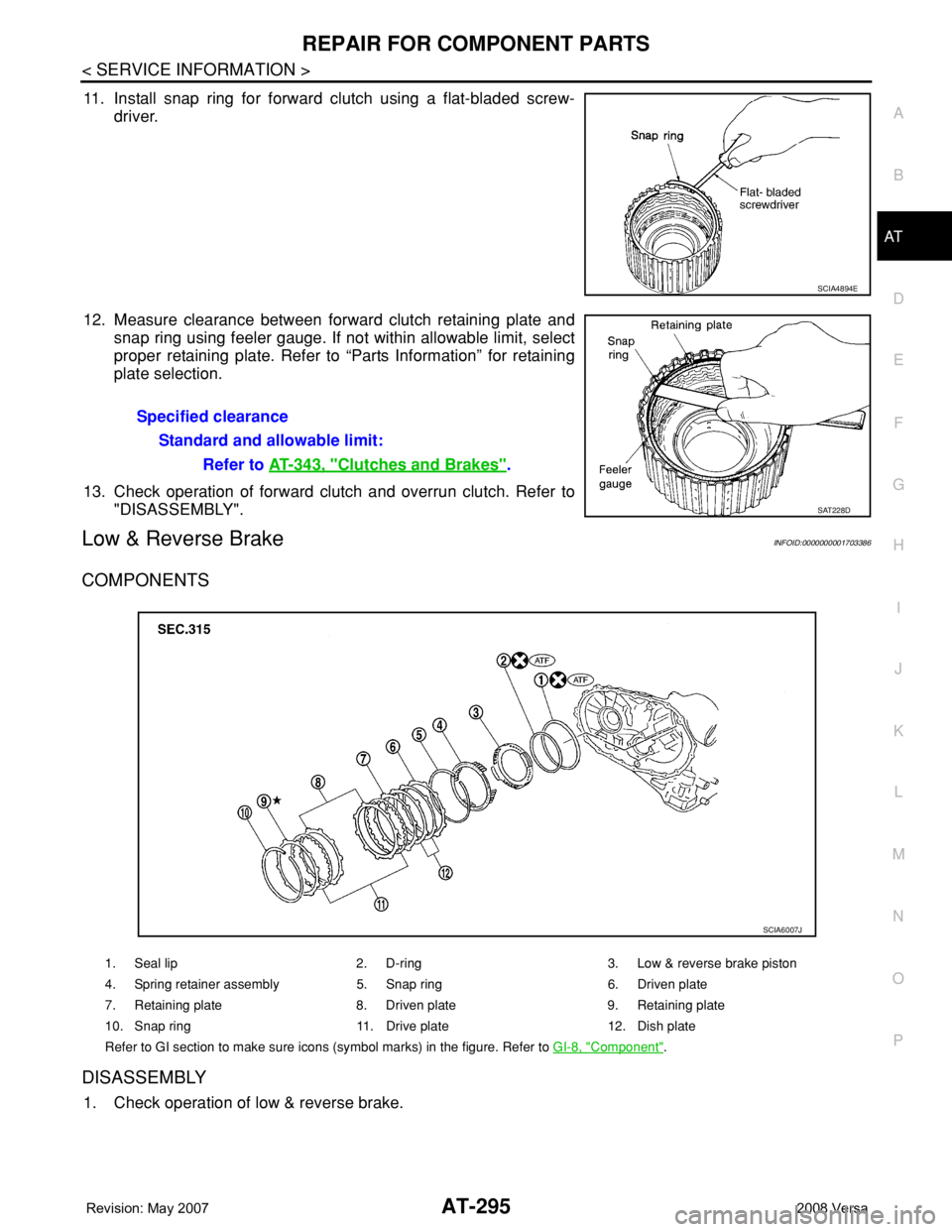
11. Install snap ring for forward clutch using a flat-bladed screw-
driver.
12. Measure clearance between forward clutch retaining plate and
snap ring using feeler gauge. If not within allowable limit, select
proper retaining plate. Refer to “Parts Information” for retaining
plate selection.
13. Check operation of forward clutch and overrun clutch. Refer to
"DISASSEMBLY".
Low & Reverse BrakeINFOID:0000000001703386
COMPONENTS
DISASSEMBLY
1. Check operation of low & reverse brake.
SCIA4894E
Specified clearance
Standard and allowable limit:
Refer to AT-343, "
Clutches and Brakes".
SAT228D
1. Seal lip 2. D-ring 3. Low & reverse brake piston
4. Spring retainer assembly 5. Snap ring 6. Driven plate
7. Retaining plate 8. Driven plate 9. Retaining plate
10. Snap ring 11. Drive plate 12. Dish plate
Refer to GI section to make sure icons (symbol marks) in the figure. Refer to GI-8, "
Component".
SCIA6007J
Page 309 of 2771
REPAIR FOR COMPONENT PARTS
AT-297
< SERVICE INFORMATION >
D
E
F
G
H
I
J
K
L
MA
B
AT
N
O
P
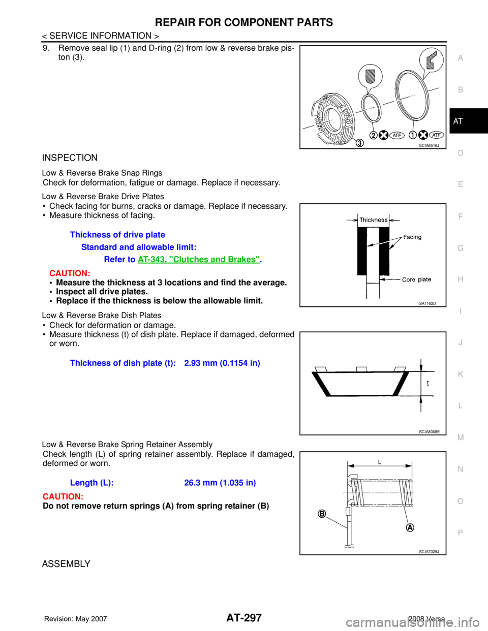
9. Remove seal lip (1) and D-ring (2) from low & reverse brake pis-
ton (3).
INSPECTION
Low & Reverse Brake Snap Rings
Check for deformation, fatigue or damage. Replace if necessary.
Low & Reverse Brake Drive Plates
• Check facing for burns, cracks or damage. Replace if necessary.
• Measure thickness of facing.
CAUTION:
• Measure the thickness at 3 locations and find the average.
• Inspect all drive plates.
• Replace if the thickness is below the allowable limit.
Low & Reverse Brake Dish Plates
• Check for deformation or damage.
• Measure thickness (t) of dish plate. Replace if damaged, deformed
or worn.
Low & Reverse Brake Spring Retainer Assembly
Check length (L) of spring retainer assembly. Replace if damaged,
deformed or worn.
CAUTION:
Do not remove return springs (A) from spring retainer (B)
ASSEMBLY
SCIA6516J
Thickness of drive plate
Standard and allowable limit:
Refer to AT-343, "
Clutches and Brakes".
SAT162D
Thickness of dish plate (t): 2.93 mm (0.1154 in)
SCIA8008E
Length (L): 26.3 mm (1.035 in)
SCIA7025J
Page 311 of 2771
REPAIR FOR COMPONENT PARTS
AT-299
< SERVICE INFORMATION >
D
E
F
G
H
I
J
K
L
MA
B
AT
N
O
P
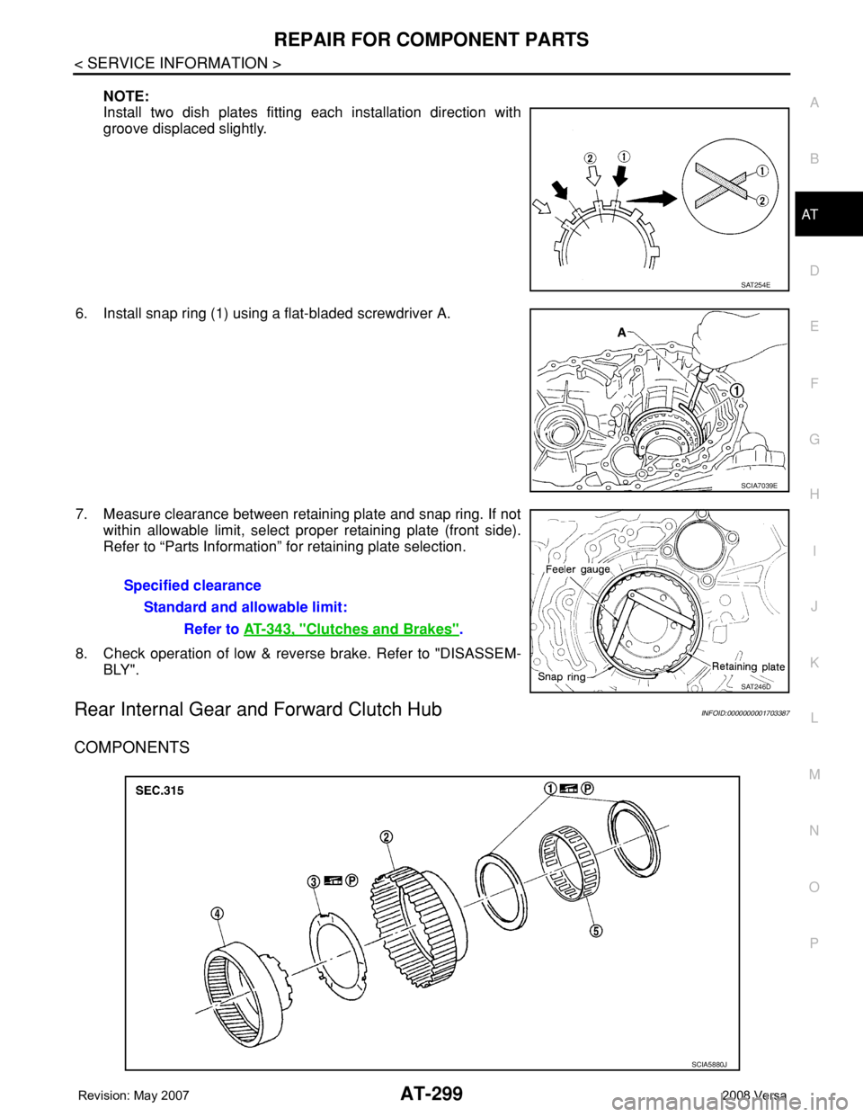
NOTE:
Install two dish plates fitting each installation direction with
groove displaced slightly.
6. Install snap ring (1) using a flat-bladed screwdriver A.
7. Measure clearance between retaining plate and snap ring. If not
within allowable limit, select proper retaining plate (front side).
Refer to “Parts Information” for retaining plate selection.
8. Check operation of low & reverse brake. Refer to "DISASSEM-
BLY".
Rear Internal Gear and Forward Clutch HubINFOID:0000000001703387
COMPONENTS
SAT254E
SCIA7039E
Specified clearance
Standard and allowable limit:
Refer to AT-343, "
Clutches and Brakes".
SAT246D
SCIA5880J
Page 355 of 2771

SERVICE DATA AND SPECIFICATIONS (SDS)
AT-343
< SERVICE INFORMATION >
D
E
F
G
H
I
J
K
L
MA
B
AT
N
O
P
Control ValvesINFOID:0000000001703402
CONTROL VALVE SPRINGS
Unit: mm (in)
AccumulatorINFOID:0000000001703403
RETURN SPRINGS
Unit: mm (in)
Unit: mm (in)
O-RINGS
Unit: mm (in)
Clutches and BrakesINFOID:0000000001703404
REVERSE CLUTCH
Location spring designation Free length (l) Outer diameter (D)
Upper bodyL14 Pilot valve spring 38.98 (1.5346) 8.9 (0.350)
L151–2 accumulator valve spring 20.5 (0.807) 6.95 (0.2736)
1–2 accumulator piston spring 55.66 (2.1913) 19.5 (0.768)
L16 1st reducing valve spring 27.0 (1.063) 7.0 (0.276)
L17 3–2 timing valve spring 23.0 (0.906) 6.65 (0.2618)
L18 Overrun clutch reducing valve spring 37.5 (1.476) 7.0 (0.276)
L19 Torque converter relief valve spring 33.3 (1.311) 9.0 (0.354)
L20 Torque converter clutch control valve spring 53.01 (2.0870) 6.5 (0.256)
L21 Cooler check valve spring 28.04 (1.1039) 7.15 (0.2815)
Lower bodyL3 Pressure regulator valve spring 45.0 (1.772) 15.0 (0.591)
L4 Overrun clutch control valve spring 21.7 (0.854) 7.0 (0.276)
L5 Accumulator control valve spring 22.0 (0.866) 6.5 (0.256)
L6 Shift valve A spring 21.7 (0.854) 7.0 (0.276)
L7 Shuttle valve spring 51.0 (2.008) 5.65 (0.2224)
L12 Shift valve B spring 21.7 (0.854) 7.0 (0.276)
L13Pressure modifier valve spring 32.0 (1.260) 6.9 (0.272)
Pressure modifier piston spring 30.5 (1.201) 9.8 (0.386)
— Line pressure relief valve spring 17.02 (0.6701) 8.0 (0.315)
— Torque converter pressure holding spring 9.0 (0.354) 7.3 (0.287)
Location Free length (L1)
Servo release accumulator 62.8 (2.472)
Location Length (L2)
N-D accumulator46.5 (1.831)
Location Inner diameter (Small) Inner diameter (Large)
Servo release accumulator 26.9 (1.059) 44.2 (1.740)
N-D accumulator 34.6 (1.362) 39.4 (1.551)
Number of drive plates2
Number of driven plates2
Drive plate thickness [mm (in)]Standard 2.0 (0.079)
Allowable limit 1.8 (0.071)
Page 732 of 2771

BR-1
BRAKES
C
D
E
G
H
I
J
K
L
M
SECTION BR
A
B
BR
N
O
P
CONTENTS
BRAKE SYSTEM
SERVICE INFORMATION ............................2
PRECAUTIONS ...................................................2
Precaution for Supplemental Restraint System
(SRS) "AIR BAG" and "SEAT BELT PRE-TEN-
SIONER" ...................................................................
2
Precaution for Brake System ....................................2
PREPARATION ...................................................3
Commercial Service Tool ..........................................3
NOISE, VIBRATION AND HARSHNESS
(NVH) TROUBLESHOOTING .............................
4
NVH Troubleshooting Chart ......................................4
BRAKE PEDAL ...................................................5
Inspection and Adjustment ........................................5
Removal and Installation ...........................................6
BRAKE FLUID .....................................................8
On Board Inspection .................................................8
Drain and Refill ..........................................................8
Bleeding Brake System .............................................8
BRAKE TUBE AND HOSE ................................10
Hydraulic Circuit ......................................................10
Front Brake Tube and Hose ....................................10
Rear Brake Tube and Hose ....................................11
Inspection After Installation .....................................11
BRAKE MASTER CYLINDER ............................13
On-Board Inspection ...............................................13
Removal and Installation .........................................13
Disassembly and Assembly ....................................13
BRAKE BOOSTER ...........................................18
On Board Inspection ................................................18
Removal and Installation .........................................18
VACUUM LINES ...............................................21
Component ..............................................................21
Removal and Installation .........................................21
Inspection ................................................................21
FRONT DISC BRAKE .......................................23
On Board Inspection ................................................23
Component ..............................................................23
Removal and Installation of Brake Pad ...................24
Removal and Installation of Brake Caliper Assem-
bly ............................................................................
25
Disassembly and Assembly of Brake Caliper As-
sembly .....................................................................
25
Brake Burnishing Procedure ....................................28
REAR DRUM BRAKE .......................................29
Component ..............................................................29
Removal and Installation of Drum Brake Assembly
....
29
Removal and Installation of Wheel Cylinder ............32
Disassembly and Assembly of Wheel Cylinder .......32
SERVICE DATA AND SPECIFICATIONS
(SDS) .................................................................
33
General Specification ..............................................33
Brake Pedal .............................................................33
Check Valve ............................................................33
Brake Booster ..........................................................33
Front Disc Brake ......................................................33
Rear Drum Brake .....................................................34
Page 766 of 2771

BRC-1
BRAKES
C
D
E
G
H
I
J
K
L
M
SECTION BRC
A
B
BRC
N
O
P
CONTENTS
BRAKE CONTROL SYSTEM
ABS
SERVICE INFORMATION ............................
2
PRECAUTIONS ...................................................2
Precaution for Supplemental Restraint System
(SRS) "AIR BAG" and "SEAT BELT PRE-TEN-
SIONER" ...................................................................
2
Precaution for Brake System ....................................2
Precaution for Brake Control .....................................2
Precaution for CAN System ......................................3
PREPARATION ...................................................4
Special Service Tool .................................................4
Commercial Service Tool ..........................................4
SYSTEM DESCRIPTION .....................................5
System Component ...................................................5
ABS Function ............................................................5
EBD Function ............................................................5
Fail-Safe Function .....................................................5
Hydraulic Circuit Diagram .........................................6
CAN COMMUNICATION .....................................7
System Description ...................................................7
TROUBLE DIAGNOSIS ......................................8
How to Perform Trouble Diagnosis for Quick and
Accurate Repair ........................................................
8
Component Parts and Harness Connector Loca-
tion ..........................................................................
11
Schematic ...............................................................12
Wiring Diagram - ABS - ...........................................13
Basic Inspection ......................................................16
Warning Lamp and Indicator Timing ........................17
Control Unit Input/Output Signal Standard ..............17
CONSULT-III Function (ABS) ..................................18
TROUBLE DIAGNOSIS FOR SELF-DIAG-
NOSTIC ITEMS .................................................
24
Wheel Sensor System .............................................24
ABS Control Unit Inspection ....................................25
Solenoid Valve System Inspection ..........................25
Actuator Motor, Motor Relay, and Circuit Inspec-
tion ...........................................................................
26
ABS Control Unit Power and Ground Systems In-
spection ...................................................................
27
CAN Communication System Inspection .................28
TROUBLE DIAGNOSES FOR SYMPTOMS .....29
ABS Works Frequently ............................................29
Unexpected Pedal Action ........................................29
Long Stopping Distance ..........................................30
ABS Does Not Work ................................................30
Pedal Vibration or ABS Operation Noise .................30
WHEEL SENSORS ...........................................32
Removal and Installation .........................................32
SENSOR ROTOR ..............................................34
Removal and Installation .........................................34
ACTUATOR AND ELECTRIC UNIT (ASSEM-
BLY) ..................................................................
35
Removal and Installation .........................................35