2008 NISSAN TIIDA air control
[x] Cancel search: air controlPage 68 of 2771
AT-56
< SERVICE INFORMATION >
TROUBLE DIAGNOSIS
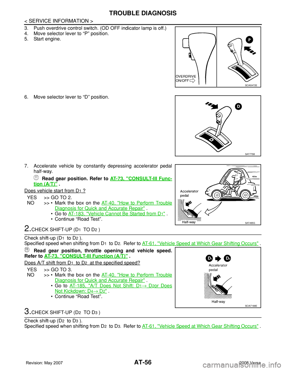
3. Push overdrive control switch. (OD OFF indicator lamp is off.)
4. Move selector lever to “P” position.
5. Start engine.
6. Move selector lever to “D” position.
7. Accelerate vehicle by constantly depressing accelerator pedal
half-way.
Read gear position. Refer to AT-73, "
CONSULT-III Func-
tion (A/T)" .
Does vehicle start from D
1 ?
YES >> GO TO 2.
NO >> • Mark the box on the AT-40, "
How to Perform Trouble
Diagnosis for Quick and Accurate Repair" .
•Go to AT-183, "
Vehicle Cannot Be Started from D1" .
• Continue “Road Test”.
2.CHECK SHIFT-UP (D1 TO D2 )
Check shift-up (D
1 to D2 ).
Specified speed when shifting from D
1 to D2. Refer to AT-61, "Vehicle Speed at Which Gear Shifting Occurs" .
Read gear position, throttle opening and vehicle speed.
Refer to AT-73, "
CONSULT-III Function (A/T)" .
Does A/T shift from D
1 to D2 at the specified speed?
YES >> GO TO 3.
NO >> • Mark the box on the AT-40, "
How to Perform Trouble
Diagnosis for Quick and Accurate Repair" .
•Go to AT-185, "
A/T Does Not Shift: D1→ D2or Does
Not Kickdown: D4→ D2" .
• Continue “Road Test”.
3.CHECK SHIFT-UP (D2 TO D3 )
Check shift-up (D
2 to D3 ).
Specified speed when shifting from D
2 to D3. Refer to AT-61, "Vehicle Speed at Which Gear Shifting Occurs" .
SCIA5472E
SAT775B
SAT495G
SCIA7188E
Page 70 of 2771
AT-58
< SERVICE INFORMATION >
TROUBLE DIAGNOSIS
• Continue “Road Test”.
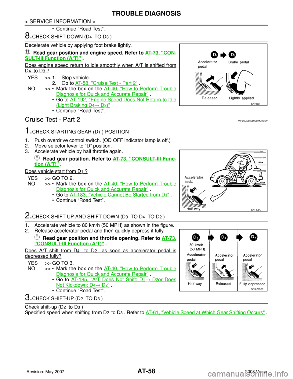
8.CHECK SHIFT-DOWN (D4 TO D3 )
Decelerate vehicle by applying foot brake lightly.
Read gear position and engine speed. Refer to AT-73, "
CON-
SULT-III Function (A/T)" .
Does engine speed return to idle smoothly when A/T is shifted from
D4 to D3 ?
YES >> 1. Stop vehicle.
2. Go to AT-58, "
Cruise Test - Part 2" .
NO >> • Mark the box on the AT-40, "
How to Perform Trouble
Diagnosis for Quick and Accurate Repair" .
•Go to AT-192, "
Engine Speed Does Not Return to Idle
(Light Braking D4→ D3)" .
• Continue “Road Test”.
Cruise Test - Part 2INFOID:0000000001703187
1.CHECK STARTING GEAR (D1 ) POSITION
1. Push overdrive control switch. (OD OFF indicator lamp is off.)
2. Move selector lever to “D” position.
3. Accelerate vehicle by half throttle again.
Read gear position. Refer to AT-73, "
CONSULT-III Func-
tion (A/T)" .
Does vehicle start from D
1 ?
YES >> GO TO 2.
NO >> • Mark the box on the AT-40, "
How to Perform Trouble
Diagnosis for Quick and Accurate Repair" .
•Go to AT-183, "
Vehicle Cannot Be Started from D1" .
• Continue “Road Test”.
2.CHECK SHIFT-UP AND SHIFT-DOWN (D3 TO D4 TO D2 )
1. Accelerate vehicle to 80 km/h (50 MPH) as shown in the figure.
2. Release accelerator pedal and then quickly depress it fully.
Read gear position and throttle opening. Refer to AT-73,
"CONSULT-III Function (A/T)" .
Does A/T shift from D
4 to D2 as soon as accelerator pedal is
depressed fully?
YES >> GO TO 3.
NO >> • Mark the box on the AT-40, "
How to Perform Trouble
Diagnosis for Quick and Accurate Repair" .
•Go to AT-185, "
A/T Does Not Shift: D1→ D2or Does
Not Kickdown: D4→ D2" .
• Continue “Road Test”.
3.CHECK SHIFT-UP (D2 TO D3 )
Check shift-up (D
2 to D3 )
Specified speed when shifting from D
2 to D3 . Refer to AT-61, "Vehicle Speed at Which Gear Shifting Occurs" .
SAT959I
SAT495G
SCIA7192E
Page 71 of 2771
TROUBLE DIAGNOSIS
AT-59
< SERVICE INFORMATION >
D
E
F
G
H
I
J
K
L
MA
B
AT
N
O
P
Read gear position, throttle opening and vehicle speed.
Refer to AT-73, "
CONSULT-III Function (A/T)" .
Does A/T shift from D
2 to D3 at the specified speed?
YES >> GO TO 4.
NO >> • Mark the box on the AT-40, "
How to Perform Trouble
Diagnosis for Quick and Accurate Repair" .
•Go to AT-186, "
A/T Does Not Shift: D2→ D3" .
• Continue “Road Test”.
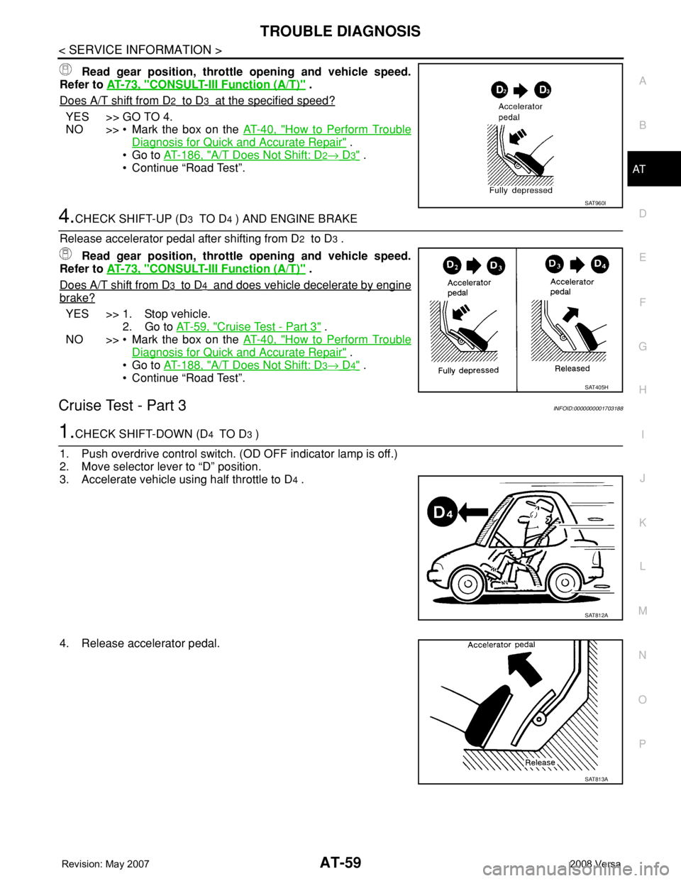
4.CHECK SHIFT-UP (D3 TO D4 ) AND ENGINE BRAKE
Release accelerator pedal after shifting from D
2 to D3 .
Read gear position, throttle opening and vehicle speed.
Refer to AT-73, "
CONSULT-III Function (A/T)" .
Does A/T shift from D
3 to D4 and does vehicle decelerate by engine
brake?
YES >> 1. Stop vehicle.
2. Go to AT-59, "
Cruise Test - Part 3" .
NO >> • Mark the box on the AT-40, "
How to Perform Trouble
Diagnosis for Quick and Accurate Repair" .
•Go to AT-188, "
A/T Does Not Shift: D3→ D4" .
• Continue “Road Test”.
Cruise Test - Part 3INFOID:0000000001703188
1.CHECK SHIFT-DOWN (D4 TO D3 )
1. Push overdrive control switch. (OD OFF indicator lamp is off.)
2. Move selector lever to “D” position.
3. Accelerate vehicle using half throttle to D
4 .
4. Release accelerator pedal.
SAT960I
SAT405H
SAT812A
SAT813A
Page 72 of 2771
AT-60
< SERVICE INFORMATION >
TROUBLE DIAGNOSIS
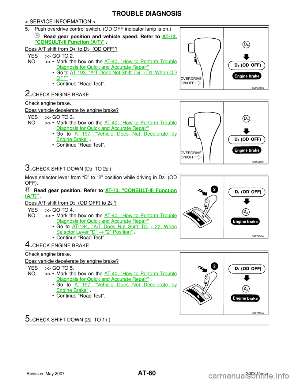
5. Push overdrive control switch. (OD OFF indicator lamp is on.)
Read gear position and vehicle speed. Refer to AT-73,
"CONSULT-III Function (A/T)" .
Does A/T shift from D
4 to D3 (OD OFF)?
YES >> GO TO 2.
NO >> • Mark the box on the AT-40, "
How to Perform Trouble
Diagnosis for Quick and Accurate Repair" .
•Go to AT-193, "
A/T Does Not Shift: D4→ D3, When OD
OFF" .
• Continue “Road Test”.
2.CHECK ENGINE BRAKE
Check engine brake.
Does vehicle decelerate by engine brake?
YES >> GO TO 3.
NO >> • Mark the box on the AT-40, "
How to Perform Trouble
Diagnosis for Quick and Accurate Repair" .
•Go to AT-197, "
Vehicle Does Not Decelerate by
Engine Brake" .
• Continue “Road Test”.
3.CHECK SHIFT-DOWN (D3 TO 22 )
Move selector lever from “D” to “2” position while driving in D
3 (OD
OFF).
Read gear position. Refer to AT-73, "
CONSULT-III Function
(A/T)" .
Does A/T shift from D
3 (OD OFF) to 22 ?
YES >> GO TO 4.
NO >> • Mark the box on the AT-40, "
How to Perform Trouble
Diagnosis for Quick and Accurate Repair" .
•Go to AT-194, "
A/T Does Not Shift: D3→ 22, When
Selector Lever "D" → "2" Position" .
• Continue “Road Test”.
4.CHECK ENGINE BRAKE
Check engine brake.
Does vehicle decelerate by engine brake?
YES >> GO TO 5.
NO >> • Mark the box on the AT-40, "
How to Perform Trouble
Diagnosis for Quick and Accurate Repair" .
•Go to AT-197, "
Vehicle Does Not Decelerate by
Engine Brake" .
• Continue “Road Test”.
5.CHECK SHIFT-DOWN (22 TO 11 )
SCIA5469E
SCIA5469E
SAT791GA
SAT791GA
Page 87 of 2771
TROUBLE DIAGNOSIS
AT-75
< SERVICE INFORMATION >
D
E
F
G
H
I
J
K
L
MA
B
AT
N
O
P
SELF-DIAGNOSTIC RESULT MODE
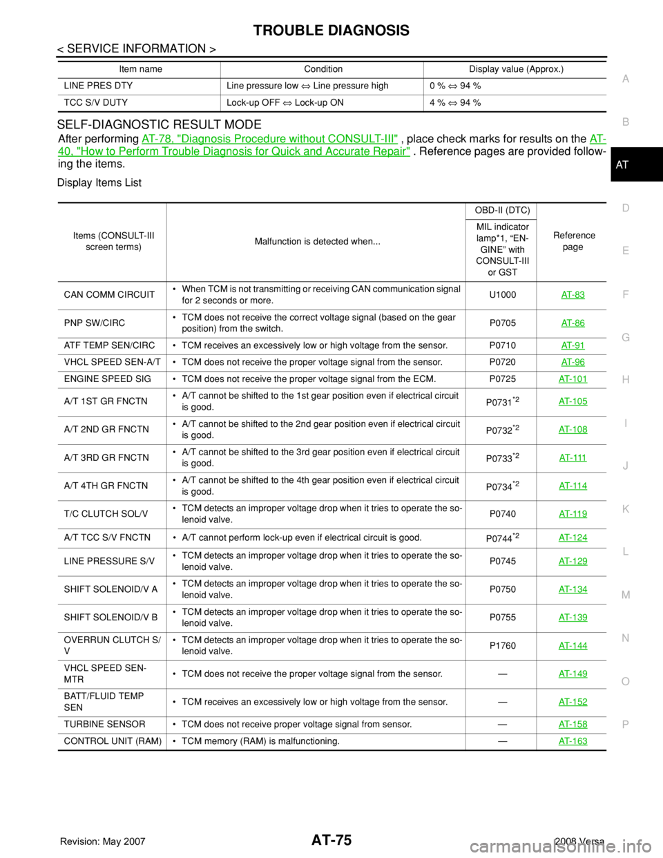
After performing AT-78, "Diagnosis Procedure without CONSULT-III" , place check marks for results on the AT-
40, "How to Perform Trouble Diagnosis for Quick and Accurate Repair" . Reference pages are provided follow-
ing the items.
Display Items List
LINE PRES DTY Line pressure low ⇔ Line pressure high 0 % ⇔ 94 %
TCC S/V DUTY Lock-up OFF ⇔ Lock-up ON 4 % ⇔ 94 % Item name Condition Display value (Approx.)
Items (CONSULT-III
screen terms)Malfunction is detected when...OBD-II (DTC)
Reference
page MIL indicator
lamp*1, “EN-
GINE” with
CONSULT-III
or GST
CAN COMM CIRCUIT• When TCM is not transmitting or receiving CAN communication signal
for 2 seconds or more.U1000AT- 8 3
PNP SW/CIRC• TCM does not receive the correct voltage signal (based on the gear
position) from the switch.P0705AT- 8 6
ATF TEMP SEN/CIRC • TCM receives an excessively low or high voltage from the sensor. P0710AT- 9 1
VHCL SPEED SEN-A/T • TCM does not receive the proper voltage signal from the sensor. P0720AT- 9 6
ENGINE SPEED SIG • TCM does not receive the proper voltage signal from the ECM. P0725AT- 1 0 1
A/T 1ST GR FNCTN• A/T cannot be shifted to the 1st gear position even if electrical circuit
is good.P0731*2AT- 1 0 5
A/T 2ND GR FNCTN• A/T cannot be shifted to the 2nd gear position even if electrical circuit
is good.P0732*2AT- 1 0 8
A/T 3RD GR FNCTN• A/T cannot be shifted to the 3rd gear position even if electrical circuit
is good.P0733*2AT- 111
A/T 4TH GR FNCTN• A/T cannot be shifted to the 4th gear position even if electrical circuit
is good.P0734*2AT- 11 4
T/C CLUTCH SOL/V• TCM detects an improper voltage drop when it tries to operate the so-
lenoid valve.P0740AT- 11 9
A/T TCC S/V FNCTN • A/T cannot perform lock-up even if electrical circuit is good.
P0744*2AT- 1 2 4
LINE PRESSURE S/V• TCM detects an improper voltage drop when it tries to operate the so-
lenoid valve.P0745AT- 1 2 9
SHIFT SOLENOID/V A• TCM detects an improper voltage drop when it tries to operate the so-
lenoid valve.P0750AT- 1 3 4
SHIFT SOLENOID/V B• TCM detects an improper voltage drop when it tries to operate the so-
lenoid valve.P0755 AT- 1 3 9
OVERRUN CLUTCH S/
V• TCM detects an improper voltage drop when it tries to operate the so-
lenoid valve.P1760AT- 1 4 4
VHCL SPEED SEN-
MTR• TCM does not receive the proper voltage signal from the sensor. —AT- 1 4 9
BATT/FLUID TEMP
SEN• TCM receives an excessively low or high voltage from the sensor. —AT- 1 5 2
TURBINE SENSOR • TCM does not receive proper voltage signal from sensor. —AT- 1 5 8
CONTROL UNIT (RAM) • TCM memory (RAM) is malfunctioning. —AT- 1 6 3
Page 94 of 2771
AT-82
< SERVICE INFORMATION >
TROUBLE DIAGNOSIS
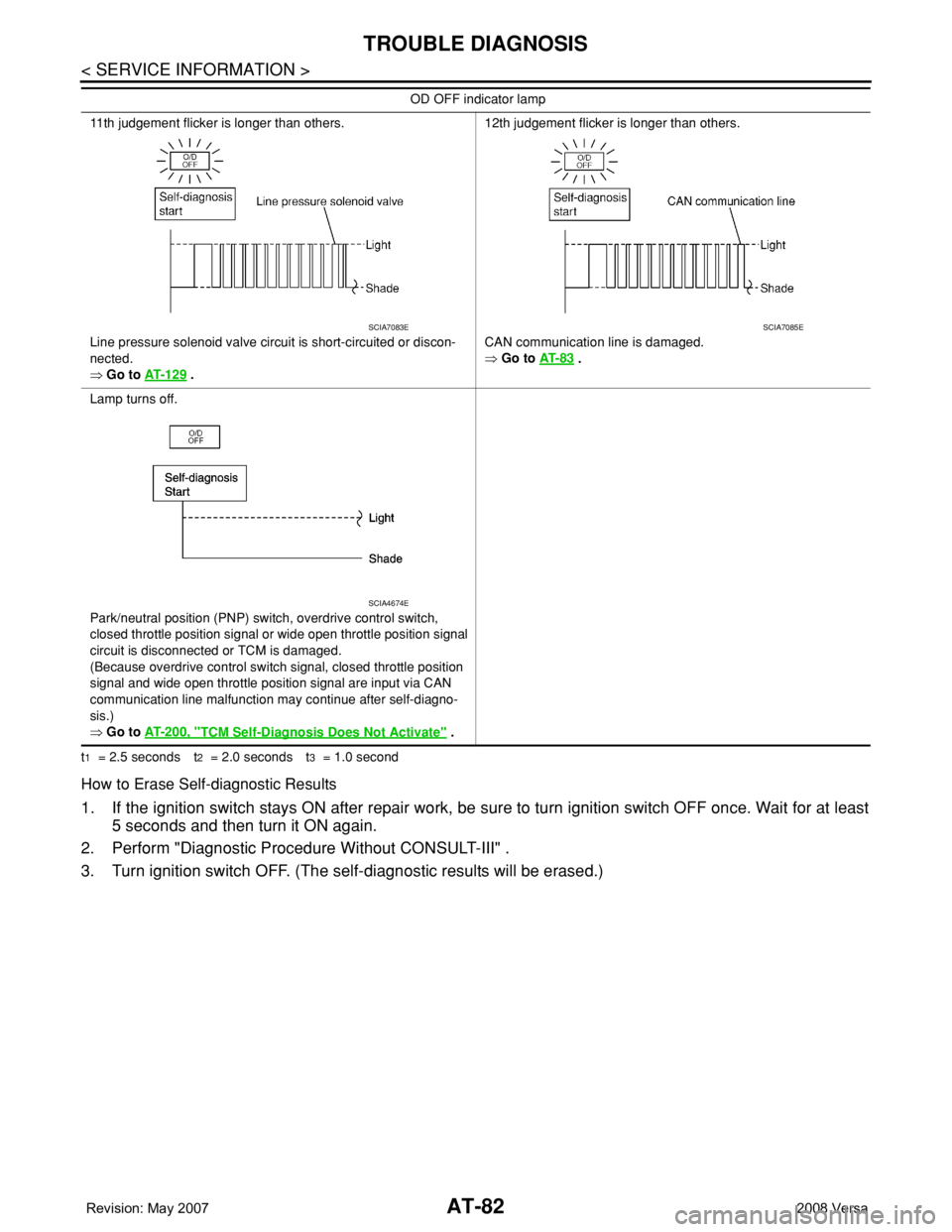
t1 = 2.5 seconds t2 = 2.0 seconds t3 = 1.0 second
How to Erase Self-diagnostic Results
1. If the ignition switch stays ON after repair work, be sure to turn ignition switch OFF once. Wait for at least
5 seconds and then turn it ON again.
2. Perform "Diagnostic Procedure Without CONSULT-III" .
3. Turn ignition switch OFF. (The self-diagnostic results will be erased.)
11th judgement flicker is longer than others.
Line pressure solenoid valve circuit is short-circuited or discon-
nected.
⇒ Go to AT- 1 2 9
.12th judgement flicker is longer than others.
CAN communication line is damaged.
⇒ Go to AT- 8 3
.
Lamp turns off.
Park/neutral position (PNP) switch, overdrive control switch,
closed throttle position signal or wide open throttle position signal
circuit is disconnected or TCM is damaged.
(Because overdrive control switch signal, closed throttle position
signal and wide open throttle position signal are input via CAN
communication line malfunction may continue after self-diagno-
sis.)
⇒ Go to AT- 2 0 0 , "
TCM Self-Diagnosis Does Not Activate" . OD OFF indicator lamp
SCIA7083ESCIA7085E
SCIA4674E
Page 95 of 2771
DTC U1000 CAN COMMUNICATION LINE
AT-83
< SERVICE INFORMATION >
D
E
F
G
H
I
J
K
L
MA
B
AT
N
O
P
DTC U1000 CAN COMMUNICATION LINE
DescriptionINFOID:0000000001703195
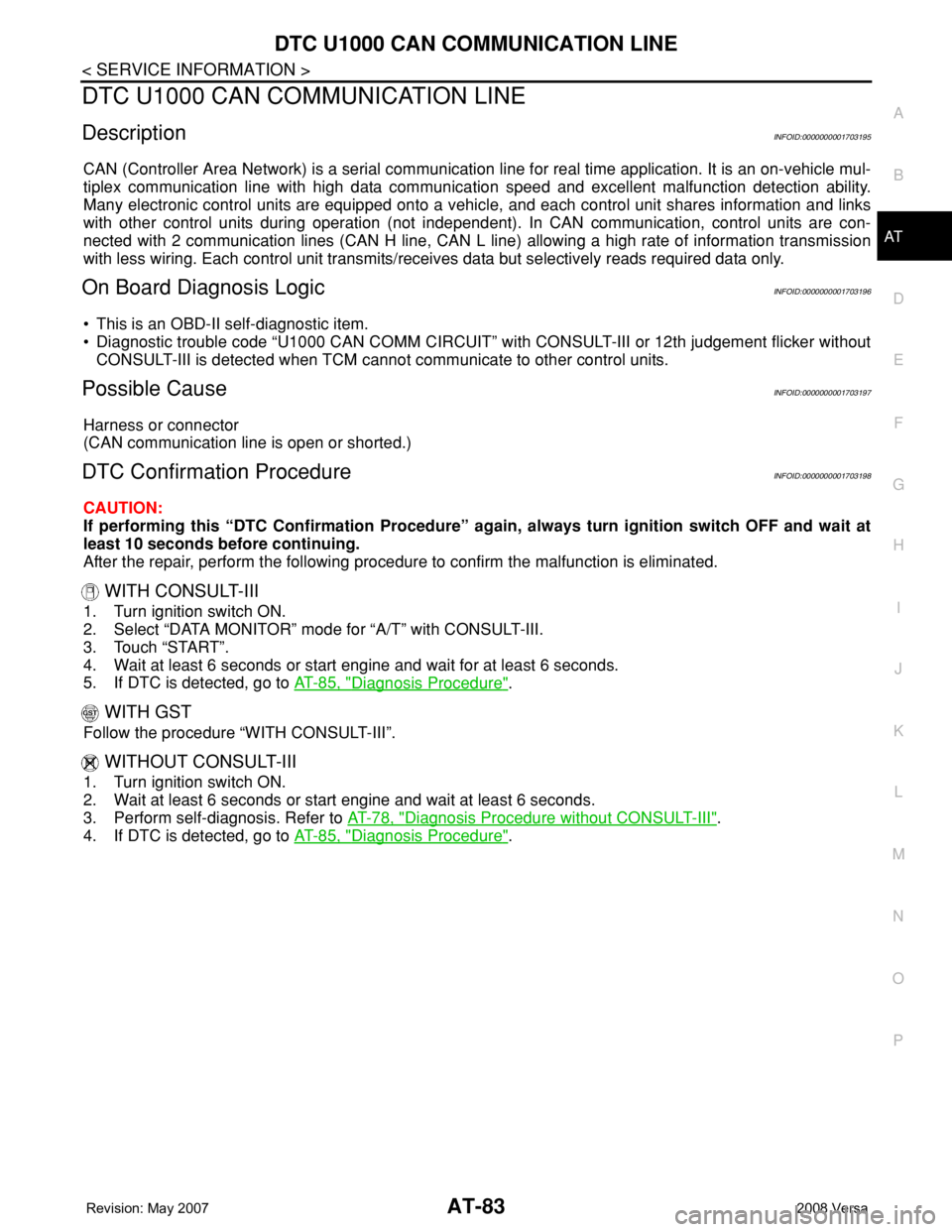
CAN (Controller Area Network) is a serial communication line for real time application. It is an on-vehicle mul-
tiplex communication line with high data communication speed and excellent malfunction detection ability.
Many electronic control units are equipped onto a vehicle, and each control unit shares information and links
with other control units during operation (not independent). In CAN communication, control units are con-
nected with 2 communication lines (CAN H line, CAN L line) allowing a high rate of information transmission
with less wiring. Each control unit transmits/receives data but selectively reads required data only.
On Board Diagnosis LogicINFOID:0000000001703196
• This is an OBD-II self-diagnostic item.
• Diagnostic trouble code “U1000 CAN COMM CIRCUIT” with CONSULT-III or 12th judgement flicker without
CONSULT-III is detected when TCM cannot communicate to other control units.
Possible CauseINFOID:0000000001703197
Harness or connector
(CAN communication line is open or shorted.)
DTC Confirmation ProcedureINFOID:0000000001703198
CAUTION:
If performing this “DTC Confirmation Procedure” again, always turn ignition switch OFF and wait at
least 10 seconds before continuing.
After the repair, perform the following procedure to confirm the malfunction is eliminated.
WITH CONSULT-III
1. Turn ignition switch ON.
2. Select “DATA MONITOR” mode for “A/T” with CONSULT-III.
3. Touch “START”.
4. Wait at least 6 seconds or start engine and wait for at least 6 seconds.
5. If DTC is detected, go to AT-85, "
Diagnosis Procedure".
WITH GST
Follow the procedure “WITH CONSULT-III”.
WITHOUT CONSULT-III
1. Turn ignition switch ON.
2. Wait at least 6 seconds or start engine and wait at least 6 seconds.
3. Perform self-diagnosis. Refer to AT-78, "
Diagnosis Procedure without CONSULT-III".
4. If DTC is detected, go to AT-85, "
Diagnosis Procedure".
Page 101 of 2771
DTC P0705 PARK/NEUTRAL POSITION (PNP) SWITCH
AT-89
< SERVICE INFORMATION >
D
E
F
G
H
I
J
K
L
MA
B
AT
N
O
P
NG >> GO TO 3.
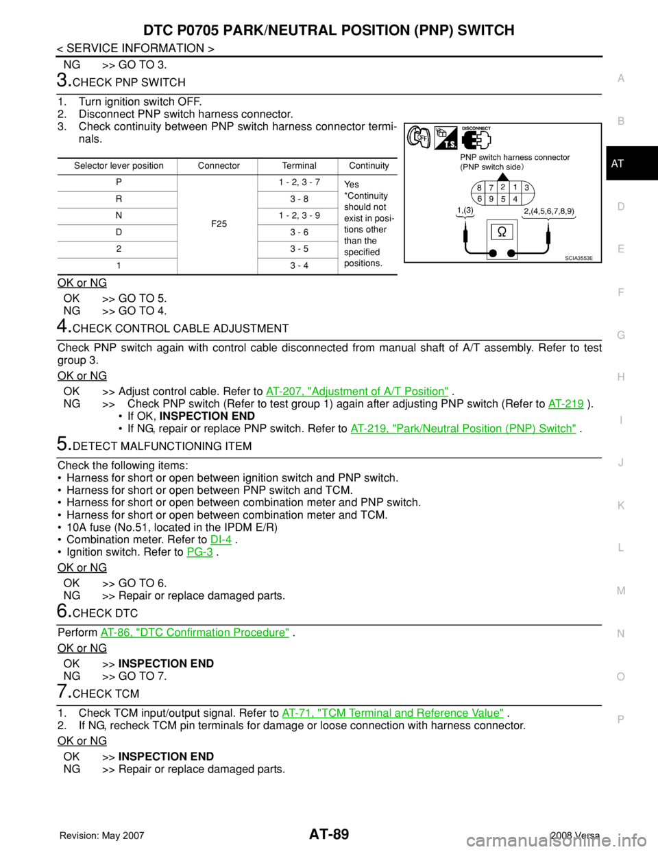
3.CHECK PNP SWITCH
1. Turn ignition switch OFF.
2. Disconnect PNP switch harness connector.
3. Check continuity between PNP switch harness connector termi-
nals.
OK or NG
OK >> GO TO 5.
NG >> GO TO 4.
4.CHECK CONTROL CABLE ADJUSTMENT
Check PNP switch again with control cable disconnected from manual shaft of A/T assembly. Refer to test
group 3.
OK or NG
OK >> Adjust control cable. Refer to AT-207, "Adjustment of A/T Position" .
NG >> Check PNP switch (Refer to test group 1) again after adjusting PNP switch (Refer to AT-219
).
• If OK, INSPECTION END
• If NG, repair or replace PNP switch. Refer to AT-219, "
Park/Neutral Position (PNP) Switch" .
5.DETECT MALFUNCTIONING ITEM
Check the following items:
• Harness for short or open between ignition switch and PNP switch.
• Harness for short or open between PNP switch and TCM.
• Harness for short or open between combination meter and PNP switch.
• Harness for short or open between combination meter and TCM.
• 10A fuse (No.51, located in the IPDM E/R)
• Combination meter. Refer to DI-4
.
• Ignition switch. Refer to PG-3
.
OK or NG
OK >> GO TO 6.
NG >> Repair or replace damaged parts.
6.CHECK DTC
Perform AT-86, "
DTC Confirmation Procedure" .
OK or NG
OK >>INSPECTION END
NG >> GO TO 7.
7.CHECK TCM
1. Check TCM input/output signal. Refer to AT-71, "
TCM Terminal and Reference Value" .
2. If NG, recheck TCM pin terminals for damage or loose connection with harness connector.
OK or NG
OK >>INSPECTION END
NG >> Repair or replace damaged parts.
Selector lever position Connector Terminal Continuity
P
F251 - 2, 3 - 7
Ye s
*Continuity
should not
exist in posi-
tions other
than the
specified
positions. R3 - 8
N 1 - 2, 3 - 9
D3 - 6
23 - 5
13 - 4
SCIA3553E