2008 NISSAN TIIDA Concentric Slave Cylinder CSC
[x] Cancel search: Concentric Slave Cylinder CSCPage 802 of 2771

CL-1
TRANSMISSION/TRANSAXLE
D
E
F
G
H
I
J
K
L
M
SECTION CL
A
B
CL
N
O
P
CONTENTS
CLUTCH
SERVICE INFORMATION ............................2
PRECAUTIONS ...................................................2
Precaution for Supplemental Restraint System
(SRS) "AIR BAG" and "SEAT BELT PRE-TEN-
SIONER" ...................................................................
2
Precaution for Procedure without Cowl Top Cover ......2
Service Notice or Precaution .....................................2
PREPARATION ...................................................3
Special Service Tool .................................................3
Commercial Service Tool ..........................................3
NOISE, VIBRATION AND HARSHNESS
(NVH) TROUBLESHOOTING .............................
4
NVH Troubleshooting Chart ......................................4
CLUTCH PEDAL .................................................5
On-vehicle Inspection and Adjustment ......................5
Removal and Installation ...........................................6
CLUTCH FLUID ...................................................8
Air Bleeding Procedure .............................................8
CLUTCH MASTER CYLINDER .........................9
Removal and Installation ..........................................9
CSC (CONCENTRIC SLAVE CYLINDER) .......11
Removal and Installation .........................................11
CLUTCH PIPING ...............................................12
Removal and Installation .........................................12
CLUTCH DISC, CLUTCH COVER AND FLY-
WHEEL ..............................................................
13
Removal and Installation .........................................13
SERVICE DATA AND SPECIFICATIONS
(SDS) .................................................................
16
Clutch Control System .............................................16
Clutch Pedal ............................................................16
Clutch Disc ..............................................................16
Clutch Cover ............................................................16
Page 803 of 2771
CL-2
< SERVICE INFORMATION >
PRECAUTIONS
SERVICE INFORMATION
PRECAUTIONS
Precaution for Supplemental Restraint System (SRS) "AIR BAG" and "SEAT BELT
PRE-TENSIONER"
INFOID:0000000001703112
The Supplemental Restraint System such as “AIR BAG” and “SEAT BELT PRE-TENSIONER”, used along
with a front seat belt, helps to reduce the risk or severity of injury to the driver and front passenger for certain
types of collision. This system includes seat belt switch inputs and dual stage front air bag modules. The SRS
system uses the seat belt switches to determine the front air bag deployment, and may only deploy one front
air bag, depending on the severity of a collision and whether the front occupants are belted or unbelted.
Information necessary to service the system safely is included in the SRS and SB section of this Service Man-
ual.
WARNING:
• To avoid rendering the SRS inoperative, which could increase the risk of personal injury or death in
the event of a collision which would result in air bag inflation, all maintenance must be performed by
an authorized NISSAN/INFINITI dealer.
• Improper maintenance, including incorrect removal and installation of the SRS, can lead to personal
injury caused by unintentional activation of the system. For removal of Spiral Cable and Air Bag
Module, see the SRS section.
• Do not use electrical test equipment on any circuit related to the SRS unless instructed to in this
Service Manual. SRS wiring harnesses can be identified by yellow and/or orange harnesses or har-
ness connectors.
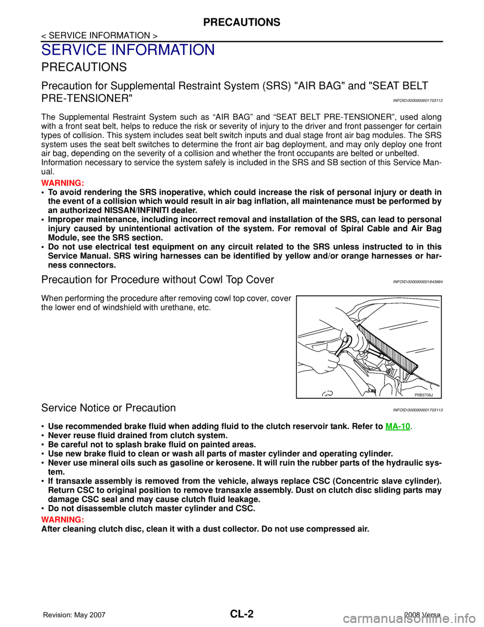
Precaution for Procedure without Cowl Top CoverINFOID:0000000001843684
When performing the procedure after removing cowl top cover, cover
the lower end of windshield with urethane, etc.
Service Notice or PrecautionINFOID:0000000001703113
•Use recommended brake fluid when adding fluid to the clutch reservoir tank. Refer to MA-10.
•Never reuse fluid drained from clutch system.
•Be careful not to splash brake fluid on painted areas.
•Use new brake fluid to clean or wash all parts of master cylinder and operating cylinder.
•Never use mineral oils such as gasoline or kerosene. It will ruin the rubber parts of the hydraulic sys-
tem.
•If transaxle assembly is removed from the vehicle, always replace CSC (Concentric slave cylinder).
Return CSC to original position to remove transaxle assembly. Dust on clutch disc sliding parts may
damage CSC seal and may cause clutch fluid leakage.
•Do not disassemble clutch master cylinder and CSC.
WARNING:
After cleaning clutch disc, clean it with a dust collector. Do not use compressed air.
PIIB3706J
Page 805 of 2771

CL-4
< SERVICE INFORMATION >
NOISE, VIBRATION AND HARSHNESS (NVH) TROUBLESHOOTING
NOISE, VIBRATION AND HARSHNESS (NVH) TROUBLESHOOTING
NVH Troubleshooting ChartINFOID:0000000001703116
Use the chart below to help you find the cause of the symptom. The numbers indicate the order of the inspec-
tion. If necessary, repair or replace these parts.
Reference pageCL-5CL-8EM-72CL-11CL-13EM-93
SUSPECTED PARTS (Possible cause)
CLUTCH PEDAL (Inspection and adjustment)
CLUTCH LINE (Air in line)
ENGINE MOUNTING (Loose)
CSC (Concentric slave cylinder) (Worn, dirty or damaged)
CLUTCH DISC (Out of true)
CLUTCH DISC (Runout is excessive)
CLUTCH DISC (Lining broken)
CLUTCH DISC (Dirty or burned)
CLUTCH DISC (Oily)
CLUTCH DISC (Worn out)
CLUTCH DISC (Hardened)
CLUTCH DISC (Lack of spline grease)
DIAPHRAGM SPRING (Damaged)
DIAPHRAGM SPRING (Out of tip alignment)
PRESSURE PLATE (Distortion)
FLYWHEEL (Distortion)
SymptomClutch grabs/chatters 1 2 2 2 2 2
Clutch pedal spongy 1
Clutch noisy 1
Clutch slips 1 2 2 3 4 5
Clutch does not disengage 12 55555 5667
Page 812 of 2771
CSC (CONCENTRIC SLAVE CYLINDER)
CL-11
< SERVICE INFORMATION >
D
E
F
G
H
I
J
K
L
MA
B
CL
N
O
P
CSC (CONCENTRIC SLAVE CYLINDER)
Removal and InstallationINFOID:0000000001703121
CAUTION:
• If transaxle assembly is removed from the vehicle, always replace CSC (Concentric slave cylinder).
Return CSC insert to original position to remove transaxle assembly. Dust on clutch disc sliding
parts may damage CSC seal and may cause clutch fluid leakage.
• Keep painted surface of the body and other parts free of clutch fluid. If it spills, wipe up immediately
and wash the affected area with water.
REMOVAL
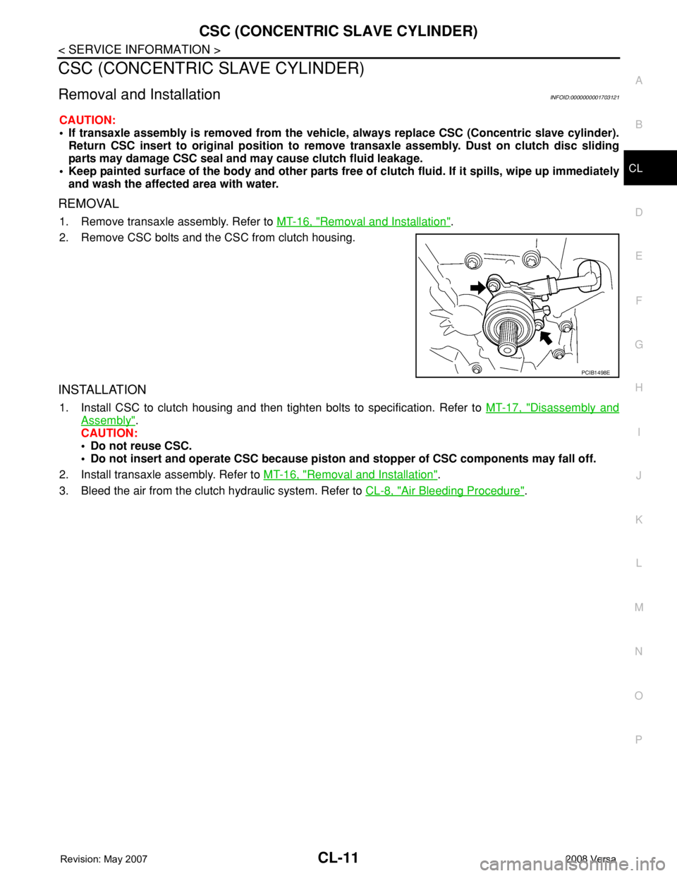
1. Remove transaxle assembly. Refer to MT-16, "Removal and Installation".
2. Remove CSC bolts and the CSC from clutch housing.
INSTALLATION
1. Install CSC to clutch housing and then tighten bolts to specification. Refer to MT-17, "Disassembly and
Assembly".
CAUTION:
• Do not reuse CSC.
• Do not insert and operate CSC because piston and stopper of CSC components may fall off.
2. Install transaxle assembly. Refer to MT-16, "
Removal and Installation".
3. Bleed the air from the clutch hydraulic system. Refer to CL-8, "
Air Bleeding Procedure".
PCIB1498E
Page 814 of 2771
CLUTCH DISC, CLUTCH COVER AND FLYWHEEL
CL-13
< SERVICE INFORMATION >
D
E
F
G
H
I
J
K
L
MA
B
CL
N
O
P
CLUTCH DISC, CLUTCH COVER AND FLYWHEEL
Removal and InstallationINFOID:0000000001703123
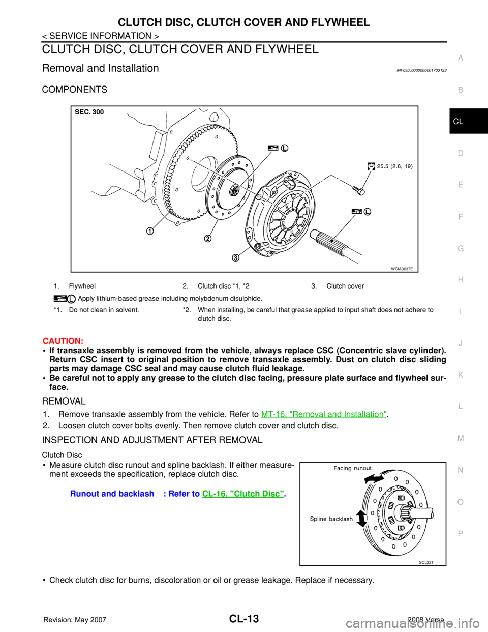
COMPONENTS
CAUTION:
• If transaxle assembly is removed from the vehicle, always replace CSC (Concentric slave cylinder).
Return CSC insert to original position to remove transaxle assembly. Dust on clutch disc sliding
parts may damage CSC seal and may cause clutch fluid leakage.
• Be careful not to apply any grease to the clutch disc facing, pressure plate surface and flywheel sur-
face.
REMOVAL
1. Remove transaxle assembly from the vehicle. Refer to MT-16, "Removal and Installation".
2. Loosen clutch cover bolts evenly. Then remove clutch cover and clutch disc.
INSPECTION AND ADJUSTMENT AFTER REMOVAL
Clutch Disc
• Measure clutch disc runout and spline backlash. If either measure-
ment exceeds the specification, replace clutch disc.
• Check clutch disc for burns, discoloration or oil or grease leakage. Replace if necessary.
1. Flywheel 2. Clutch disc *1, *2 3. Clutch cover
Apply lithium-based grease including molybdenum disulphide.
*1. Do not clean in solvent. *2. When installing, be careful that grease applied to input shaft does not adhere to
clutch disc.
WCIA0637E
Runout and backlash : Refer to CL-16, "Clutch Disc".
SCL221
Page 2290 of 2771
MT-2
< SERVICE INFORMATION >
PRECAUTIONS
SERVICE INFORMATION
PRECAUTIONS
Precaution for Supplemental Restraint System (SRS) "AIR BAG" and "SEAT BELT
PRE-TENSIONER"
INFOID:0000000001703128
The Supplemental Restraint System such as “AIR BAG” and “SEAT BELT PRE-TENSIONER”, used along
with a front seat belt, helps to reduce the risk or severity of injury to the driver and front passenger for certain
types of collision. This system includes seat belt switch inputs and dual stage front air bag modules. The SRS
system uses the seat belt switches to determine the front air bag deployment, and may only deploy one front
air bag, depending on the severity of a collision and whether the front occupants are belted or unbelted.
Information necessary to service the system safely is included in the SRS and SB section of this Service Man-
ual.
WARNING:
• To avoid rendering the SRS inoperative, which could increase the risk of personal injury or death in
the event of a collision which would result in air bag inflation, all maintenance must be performed by
an authorized NISSAN/INFINITI dealer.
• Improper maintenance, including incorrect removal and installation of the SRS, can lead to personal
injury caused by unintentional activation of the system. For removal of Spiral Cable and Air Bag
Module, see the SRS section.
• Do not use electrical test equipment on any circuit related to the SRS unless instructed to in this
Service Manual. SRS wiring harnesses can be identified by yellow and/or orange harnesses or har-
ness connectors.
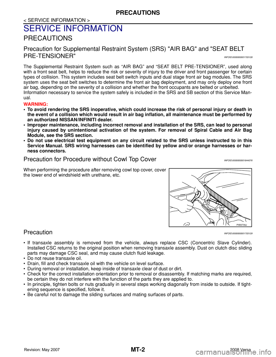
Precaution for Procedure without Cowl Top CoverINFOID:0000000001844076
When performing the procedure after removing cowl top cover, cover
the lower end of windshield with urethane, etc.
PrecautionINFOID:0000000001703129
• If transaxle assembly is removed from the vehicle, always replace CSC (Concentric Slave Cylinder).
Installed CSC returns to the original position when removing transaxle assembly. Dust on clutch disc sliding
parts may damage CSC seal, and may cause clutch fluid leakage.
• Do not reuse transaxle oil.
• Drain, fill and check transaxle oil with the vehicle on level surface.
• During removal or installation, keep inside of transaxle clear of dust or dirt.
• Check for the correct installation orientation prior to removal or disassembly. If matching marks are required,
be certain they do not interfere with the function of the parts they are applied to.
• In principle, tighten bolts or nuts gradually in several steps working diagonally from inside to outside. If tight-
ening sequence is specified, follow it.
• Be careful not to damage the sliding surfaces and mating surfaces of parts.
PIIB3706J
Page 2296 of 2771
MT-8
< SERVICE INFORMATION >
DESCRIPTION
DESCRIPTION
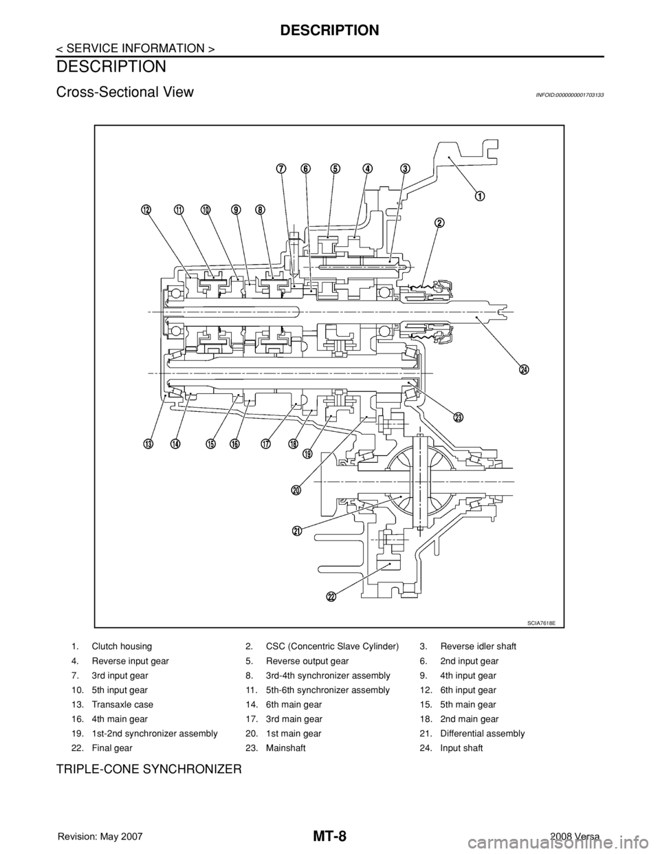
Cross-Sectional ViewINFOID:0000000001703133
TRIPLE-CONE SYNCHRONIZER
1. Clutch housing 2. CSC (Concentric Slave Cylinder) 3. Reverse idler shaft
4. Reverse input gear 5. Reverse output gear 6. 2nd input gear
7. 3rd input gear 8. 3rd-4th synchronizer assembly 9. 4th input gear
10. 5th input gear 11. 5th-6th synchronizer assembly 12. 6th input gear
13. Transaxle case 14. 6th main gear 15. 5th main gear
16. 4th main gear 17. 3rd main gear 18. 2nd main gear
19. 1st-2nd synchronizer assembly 20. 1st main gear 21. Differential assembly
22. Final gear 23. Mainshaft 24. Input shaft
SCIA7618E
Page 2304 of 2771
MT-16
< SERVICE INFORMATION >
TRANSAXLE ASSEMBLY
TRANSAXLE ASSEMBLY
Removal and InstallationINFOID:0000000001703141
CAUTION:
If transaxle assembly is removed from the vehicle, always replace CSC (Concentric Slave Cylinder).
Inserted CSC returns to the original position when removing transaxle assembly. Dust on clutch disc
sliding parts may damage CSC seal, and may cause clutch fluid leakage.
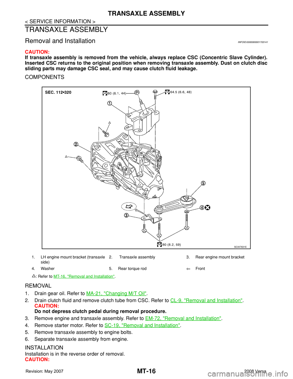
COMPONENTS
REMOVAL
1. Drain gear oil. Refer to MA-21, "Changing M/T Oil".
2. Drain clutch fluid and remove clutch tube from CSC. Refer to CL-9, "
Removal and Installation".
CAUTION:
Do not depress clutch pedal during removal procedure.
3. Remove engine and transaxle assembly. Refer to EM-72, "
Removal and Installation".
4. Remove starter motor. Refer to SC-19, "
Removal and Installation".
5. Remove transaxle assembly to engine bolts.
6. Separate transaxle assembly from engine.
INSTALLATION
Installation is in the reverse order of removal.
CAUTION:
1. LH engine mount bracket (transaxle
side)2. Transaxle assembly 3. Rear engine mount bracket
4. Washer 5. Rear torque rod⇐Front
: Refer to MT-16, "
Removal and Installation".
SCIA7631E