Page 1644 of 2771
COWL TOP
EI-21
< ON-VEHICLE REPAIR >
C
D
E
F
G
H
J
K
L
MA
B
EI
N
O
P
COWL TOP
Removal and InstallationINFOID:0000000001704223
REMOVAL
1. Remove front wiper arm RH/LH from vehicle. Refer to WW-18, "Removal and Installation of Front Wiper
Arms".
2. Disconnect washer tube.
3. Remove fender seal and fender cover RH/LH.
4. Release the cowl top seal clips, then remove cowl top seal.
LIIA2565E
1. Fender cover 2. Fender seal 3. Washer tube
4. Cowl top seal 5. Cowl extension panel 6. Dual lock fastener
7. Double-faced adhesive tape 8. Cowl top cover 9. Clip C205
10. EPT sealer 11. Cowl extension clip 12. Cover
Clip CE103⇐Vehicle front
PIIB2555J
Page 1645 of 2771
EI-22
< ON-VEHICLE REPAIR >
COWL TOP
5. Release the cowl extension clip (1) by prying the center pawls
apart and pulling clip outward. Remove remaining clips, then
remove cowl top cover (2).
6. Disconnect and remove the front wiper motor and linkage
assembly. Refer to WW-19, "
Removal and Installation of Front
Wiper Drive Assembly".
CAUTION:
To avoid damage, make sure to cover the lower edge of
windshield with suitable protection material.
7. Remove cowl extension panel bolts, then remove cowl extension panel.
INSTALLATION
Installation is in the reverse order of removal.
NOTE:
• For wiper arm RH/LH installation and adjustment, Refer to WW-18, "
Removal and Installation of Front Wiper
Arms".
• Always replace EPT sealer and double-faced adhesive tape when installing cowl top cover.
LIIA2566E
PIIB6038E
Page 1912 of 2771
WINDSHIELD GLASS
GW-11
< SERVICE INFORMATION >
C
D
E
F
G
H
J
K
L
MA
B
GW
N
O
P
WINDSHIELD GLASS
Removal and InstallationINFOID:0000000001704135
REMOVAL
1. Partially remove the headlining (front edge). Refer to EI-45.
2. Remove the front wiper arms. Refer to WW-18, "
Removal and Installation of Front Wiper Arms".
3. Remove the cowl top cover. Refer to EI-21
.
4. Disconnect the harness connector of wiper deicer.
5. Apply protective tape around the windshield glass to protect the painted surface from damage.
After removing windshield upper molding, remove glass using piano wire or power cutting tool (A) and an
inflatable pump bag (B).
• If a windshield glass is to be reused, mark the body and the glass with mating marks.
PIIB6285E
1. Windshield glass assembly 2. Dam sealant 3. Windshield molding
4. Spacer 5. Mirror base 6. Roof panel outer
7. Cowl top front 8. Adhesive 9. Front pillar outer panel
10. Cowl top cover 11. Primer
Page 1917 of 2771

GW-16
< SERVICE INFORMATION >
REAR WINDOW GLASS AND MOLDING
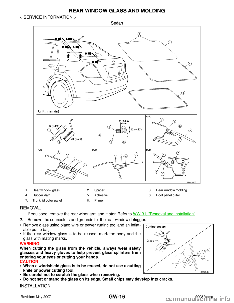
Sedan
REMOVAL
1. If equipped, remove the rear wiper arm and motor. Refer to WW-31, "Removal and Installation" .
2. Remove the connectors and grounds for the rear window defogger.
• Remove glass using piano wire or power cutting tool and an inflat-
able pump bag.
• If the rear window glass is to be reused, mark the body and the
glass with mating marks.
WARNING:
When cutting the glass from the vehicle, always wear safety
glasses and heavy gloves to help prevent glass splinters from
entering your eyes or cutting your hands.
CAUTION:
• When a windshield glass is to be reused, do not use a cutting
knife or power cutting tool.
• Be careful not to scratch the glass when removing.
• Do not set or stand the glass on its edge. Small chips may develop into cracks.
INSTALLATION
LIIA2913E
1. Rear window glass 2. Spacer 3. Rear window molding
4. Rubber dam 5. Adhesive 6. Roof panel outer
7. Trunk lid outer panel 8. Primer
SBF034B
Page 1978 of 2771
![NISSAN TIIDA 2008 Service Repair Manual IP-12
< ON-VEHICLE REPAIR >
INSTRUMENT PANEL ASSEMBLY
[ ]: Number indicates step in removal procedures.
INSTRUMENT PANEL ASSEMBLY
Removal
1. Pull instrument finisher E backward by approximately 30
deg NISSAN TIIDA 2008 Service Repair Manual IP-12
< ON-VEHICLE REPAIR >
INSTRUMENT PANEL ASSEMBLY
[ ]: Number indicates step in removal procedures.
INSTRUMENT PANEL ASSEMBLY
Removal
1. Pull instrument finisher E backward by approximately 30
deg](/manual-img/5/57399/w960_57399-1977.png)
IP-12
< ON-VEHICLE REPAIR >
INSTRUMENT PANEL ASSEMBLY
[ ]: Number indicates step in removal procedures.
INSTRUMENT PANEL ASSEMBLY
Removal
1. Pull instrument finisher E backward by approximately 30
degrees while disengaging the instrument finisher E metal clips
and pawl.
Glove box assembly"GLOVE
BOX AS-
SEMBLY"[ 15 ]
Side ventilator assembly (RH)IP-10
[ 16 ] [ 4 ]
Passenger air bag module assemblySRS-38
[ 17 ] [ 5 ]
Instrument upper maskIP-10
[ 18 ]
Instrument finisher DIP-10
[ 19 ]
Controller MTC-55
[ 20 ]
Instrument upper panel assembly IP-10
[ 21 ]
Console mask"Remov-
al"[ 22 ] [ 1 ]
CVT, A/T console finisherIP-23
[ 23 ] [ 2 ]
M/T console bootIP-23
[ 23 ] [ 2 ]
Console rear finisherIP-23
[ 24 ] [ 3 ]
Console mask cover (with arm rest)IP-23
[ 25 ] [ 4 ]
Rear cup holder (without arm rest)IP-23
[ 25 ] [ 4 ]
Console body assemblyIP-23
[ 26 ] [ 5 ]
Instrument lower cover (LH/RH)"INSTRU-
MENT
LOWER
FINISH-
ER"[ 27 ] [ 6 ]
Center console assembly"CEN-
TER
CON-
SOLE AS-
SEMBLY"[ 28 ] [ 7 ]
Fuse block lidIP-10
[ 29 ]
Lighting and turn signal switchLT- 6 0
[ 30 ]
Wiper & washer switchWW-22
[ 31 ]
Instrument panel & padIP-10
[ 32 ] PartsReference
pageInstrument
panel and padCluster lid A Cluster lid C Passenger air
bag module
assemblyCenter con-
sole assembly
WIIA1224E
Page 1982 of 2771

IP-16
< ON-VEHICLE REPAIR >
INSTRUMENT PANEL ASSEMBLY
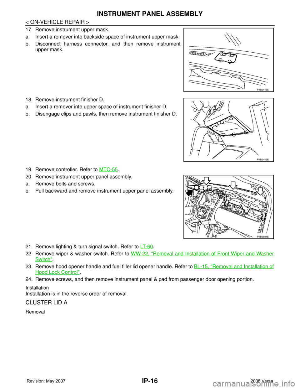
17. Remove instrument upper mask.
a. Insert a remover into backside space of instrument upper mask.
b. Disconnect harness connector, and then remove instrument
upper mask.
18. Remove instrument finisher D.
a. Insert a remover into upper space of instrument finisher D.
b. Disengage clips and pawls, then remove instrument finisher D.
19. Remove controller. Refer to MTC-55
.
20. Remove instrument upper panel assembly.
a. Remove bolts and screws.
b. Pull backward and remove instrument upper panel assembly.
21. Remove lighting & turn signal switch. Refer to LT- 6 0
.
22. Remove wiper & washer switch. Refer to WW-22, "
Removal and Installation of Front Wiper and Washer
Switch".
23. Remove hood opener handle and fuel filler lid opener handle. Refer to BL-15, "
Removal and Installation of
Hood Lock Control".
24. Remove screws, and then remove instrument panel & pad from passenger door opening portion.
Installation
Installation is in the reverse order of removal.
CLUSTER LID A
Removal
PIIB2445E
PIIB2446E
PIIB2881E
Page 2002 of 2771
TROUBLE DIAGNOSIS
LAN-11
< FUNCTION DIAGNOSIS >[CAN FUNDAMENTAL]
C
D
E
F
G
H
I
J
L
MA
B
LAN
N
O
P Example: Main Line Between Data Link Connector and ABS Actuator and Electric Unit (Control Unit) Open Circuit
Example: CAN-H, CAN-L Harness Short Circuit
SKIB8740E
Unit name Symptom
ECM Engine torque limiting is affected, and shift harshness increases.
BCM• Reverse warning chime does not sound.
• The front wiper moves under continuous operation mode even though the front wip-
er switch being in the intermittent position.
EPS control unit The steering effort increases.
Combination meter• The shift position indicator and OD OFF indicator turn OFF.
• The speedometer is inoperative.
• The odo/trip meter stops.
ABS actuator and electric unit (control unit) Normal operation.
TCM No impact on operation.
IPDM E/RWhen the ignition switch is ON,
• The headlamps (Lo) turn ON.
• The cooling fan continues to rotate.
SKIB8741E
Page 2003 of 2771
![NISSAN TIIDA 2008 Service Repair Manual LAN-12
< FUNCTION DIAGNOSIS >[CAN FUNDAMENTAL]
TROUBLE DIAGNOSIS
CAN Diagnosis with CONSULT-III
INFOID:0000000001711207
CAN diagnosis on CONSULT-III extracts the root cause by receiving the following NISSAN TIIDA 2008 Service Repair Manual LAN-12
< FUNCTION DIAGNOSIS >[CAN FUNDAMENTAL]
TROUBLE DIAGNOSIS
CAN Diagnosis with CONSULT-III
INFOID:0000000001711207
CAN diagnosis on CONSULT-III extracts the root cause by receiving the following](/manual-img/5/57399/w960_57399-2002.png)
LAN-12
< FUNCTION DIAGNOSIS >[CAN FUNDAMENTAL]
TROUBLE DIAGNOSIS
CAN Diagnosis with CONSULT-III
INFOID:0000000001711207
CAN diagnosis on CONSULT-III extracts the root cause by receiving the following information.
• Response to the system call
• Control unit diagnosis information
• Self-diagnosis
• CAN diagnostic support monitor
Self-DiagnosisINFOID:0000000001711208
CAN Diagnostic Support MonitorINFOID:0000000001711209
MONITOR ITEM (CONSULT-III)
Unit name Symptom
ECM• Engine torque limiting is affected, and shift harshness increases.
• Engine speed drops.
BCM• Reverse warning chime does not sound.
• The front wiper moves under continuous operation mode even though the front
wiper switch being in the intermittent position.
• The room lamp does not turn ON.
• The engine does not start (if an error or malfunction occurs while turning the igni-
tion switch OFF.)
• The steering lock does not release (if an error or malfunction occurs while turning
the ignition switch OFF.)
EPS control unit The steering effort increases.
Combination meter• The tachometer and the speedometer do not move.
• Warning lamps turn ON.
• Indicator lamps do not turn ON.
ABS actuator and electric unit (control unit) Normal operation.
TCM No impact on operation.
IPDM E/RWhen the ignition switch is ON,
• The headlamps (Lo) turn ON.
• The cooling fan continues to rotate.
DTCSelf-diagnosis item
(CONSULT-III indication)DTC detection condition Inspection/Action
U1000 CAN COMM CIRCUITWhen ECM is not transmitting or receiving CAN
communication signal of OBD (emission-related
diagnosis) for 2 seconds or more.
Start the inspection. Re-
fer to the applicable sec-
tion of the indicated
control unit. When a control unit (except for ECM) is not
transmitting or receiving CAN communication
signal for 2 seconds or more.
U1001 CAN COMM CIRCUITWhen ECM is not transmitting or receiving CAN
communication signal other than OBD (emis-
sion-related diagnosis) for 2 seconds or more.
U1002 SYSTEM COMMWhen a control unit is not transmitting or receiv-
ing CAN communication signal for 2 seconds or
less.
U1010 CONTROL UNIT [CAN]When an error is detected during the initial diag-
nosis for CAN controller of each control unit.Replace the control unit
indicating “U1010”.