2008 NISSAN TIIDA Defogger
[x] Cancel search: DefoggerPage 1188 of 2771
![NISSAN TIIDA 2008 Service Repair Manual EC-114
< SERVICE INFORMATION >
TROUBLE DIAGNOSIS
FUEL T/TMP SE [°C]
or [°F]ו The fuel temperature (determined by the signal
voltage of the fuel tank temperature sensor) is
displayed.
INT/A TE NISSAN TIIDA 2008 Service Repair Manual EC-114
< SERVICE INFORMATION >
TROUBLE DIAGNOSIS
FUEL T/TMP SE [°C]
or [°F]ו The fuel temperature (determined by the signal
voltage of the fuel tank temperature sensor) is
displayed.
INT/A TE](/manual-img/5/57399/w960_57399-1187.png)
EC-114
< SERVICE INFORMATION >
TROUBLE DIAGNOSIS
FUEL T/TMP SE [°C]
or [°F]ו The fuel temperature (determined by the signal
voltage of the fuel tank temperature sensor) is
displayed.
INT/A TEMP SE
[°C] or [°F]×ו The intake air temperature (determined by the
signal voltage of the intake air temperature
sensor) is indicated.
EVAP SYS PRES [V]ו The signal voltage of EVAP control system
pressure sensor is displayed.
FUEL LEVEL SE [V]ו The signal voltage of the fuel level sensor is
displayed.
START SIGNAL
[ON/OFF]×ו Indicates start signal status [ON/OFF] comput-
ed by the ECM according to the signals of en-
gine speed and battery voltage.• After starting the engine, [OFF] is
displayed regardless of the starter
signal.
CLSD THL POS
[ON/OFF]×ו Indicates idle position [ON/OFF] computed by
the ECM according to the accelerator pedal po-
sition sensor signal.
AIR COND SIG
[ON/OFF]×ו Indicates [ON/OFF] condition of the air condi-
tioner switch as determined by the air condi-
tioner signal.
P/N POSI SW
[ON/OFF]×ו Indicates [ON/OFF] condition from the park/
neutral position (PNP) switch signal.
PW/ST SIGNAL [ON/
OFF]×ו [ON/OFF] condition of the power steering sys-
tem (determined by the signal sent from EPS
control unit) is indicated.
LOAD SIGNAL
[ON/OFF]×ו Indicates [ON/OFF] condition from the electri-
cal load signal.
ON: Rear window defogger switch is ON and/
or lighting switch is in 2nd position.
OFF: Both rear window defogger switch and
lighting switch are OFF.
IGNITION SW
[ON/OFF]ו Indicates [ON/OFF] condition from ignition
switch.
HEATER FAN SW
[ON/OFF]ו Indicates [ON/OFF] condition from the heater
fan switch signal.
BRAKE SW
[ON/OFF]ו Indicates [ON/OFF] condition from the stop
lamp switch signal.
INJ PULSE-B1
[msec]ו Indicates the actual fuel injection pulse width
compensated by ECM according to the input
signals.• When the engine is stopped, a
certain computed value is indicat-
ed.
IGN TIMING [BTDC]• Indicates the ignition timing computed by ECM
according to the input signals.• When the engine is stopped, a
certain value is indicated.
CAL/LD VALUE [%]• “Calculated load value” indicates the value of
the current airflow divided by peak airflow.
MASS AIRFLOW
[g·m/s]• Indicates the mass airflow computed by ECM
according to the signal voltage of the mass air
flow sensor.
PURG VOL C/V [%]• Indicates the EVAP canister purge volume con-
trol solenoid valve control value computed by
the ECM according to the input signals.
• The opening becomes larger as the value in-
creases.
INT/V TIM (B1) [°CA]• Indicates [°CA] of intake camshaft advanced
angle. Monitored item [Unit]ECM IN-
PUT SIG-
NALSMAIN
SIG-
NALSDescription Remarks
Page 1196 of 2771

EC-122
< SERVICE INFORMATION >
TROUBLE DIAGNOSIS
THRTL SEN 1
THRTL SEN 2*• Ignition switch: ON
(Engine stopped)Accelerator pedal: Fully released More than 0.36V
• Shift lever: D (A/T, CVT),
1st (M/T)Accelerator pedal: Fully depressed Less than 4.75V
START SIGNAL • Ignition switch: ON → START → ON OFF → ON → OFF
CLSD THL POS • Ignition switch: ONAccelerator pedal: Fully released ON
Accelerator pedal: Slightly depressed OFF
AIR COND SIG• Engine: After warming up, idle the
engineAir conditioner switch: OFF OFF
Air conditioner switch: ON
(Compressor operates.)ON
P/N POSI SW • Ignition switch: ONShift lever: P or N (A/T, CVT),
Neutral (M/T)ON
Shift lever: Except above OFF
PW/ST SIGNAL• Engine: After warming up, idle the
engineSteering wheel: Not being turned OFF
Steering wheel: Being turned ON
LOAD SIGNAL • Ignition switch: ONRear window defogger switch: ON
and/or Lighting switch: 2ndON
Rear window defogger switch and light-
ing switch: OFFOFF
IGNITION SW • Ignition switch: ON → OFF → ON ON → OFF → ON
HEATER FAN SW • Ignition switch: ONHeater fan: Operating ON
Heater fan: Not operating OFF
BRAKE SW • Ignition switch: ONBrake pedal: Fully released OFF
Brake pedal: Slightly depressed ON
INJ PULSE-B1• Engine: After warming up
• Air conditioner switch: OFF
• Shift lever: P or N (A/T, CVT),
Neutral (M/T)
•No loadIdle 2.0 - 3.0 msec
2,000 rpm 1.9 - 2.9 msec
IGN TIMING• Engine: After warming up
• Air conditioner switch: OFF
• Shift lever: P or N (A/T, CVT),
Neutral (M/T)
•No loadIdle 8° - 18° BTDC
2,000 rpm 25° - 45° BTDC
CAL/LD VALUE• Engine: After warming up
• Air conditioner switch: OFF
• Shift lever: P or N (A/T, CVT),
Neutral (M/T)
•No loadIdle 10% - 35%
2,500 rpm 10% - 35%
MASS AIRFLOW• Engine: After warming up
• Air conditioner switch: OFF
• Shift lever: P or N (A/T, CVT),
Neutral (M/T)
•No loadIdle 1.0 - 4.0 g·m/s
2,500 rpm 2.0 - 10.0 g·m/s
PURG VOL C/V• Engine: After warming up
• Air conditioner switch: OFF
• Shift lever: P or N (A/T, CVT),
Neutral (M/T)
•No loadIdle
(Accelerator pedal is not depressed
even slightly, after engine starting)0%
2,000 rpm 0 - 50%
INT/V TIM (B1)• Engine: After warming up
• Air conditioner switch: OFF
• Shift lever: P or N (A/T, CVT),
Neutral (M/T)
•No loadIdle−5° - 5°CA
When revving engine up to 2,000 rpm
quicklyApprox. 0° - 40°CA MONITOR ITEM CONDITION SPECIFICATION
Page 1201 of 2771

TROUBLE DIAGNOSIS - SPECIFICATION VALUE
EC-127
< SERVICE INFORMATION >
C
D
E
F
G
H
I
J
K
L
MA
EC
N
P O
TROUBLE DIAGNOSIS - SPECIFICATION VALUE
DescriptionINFOID:0000000001702599
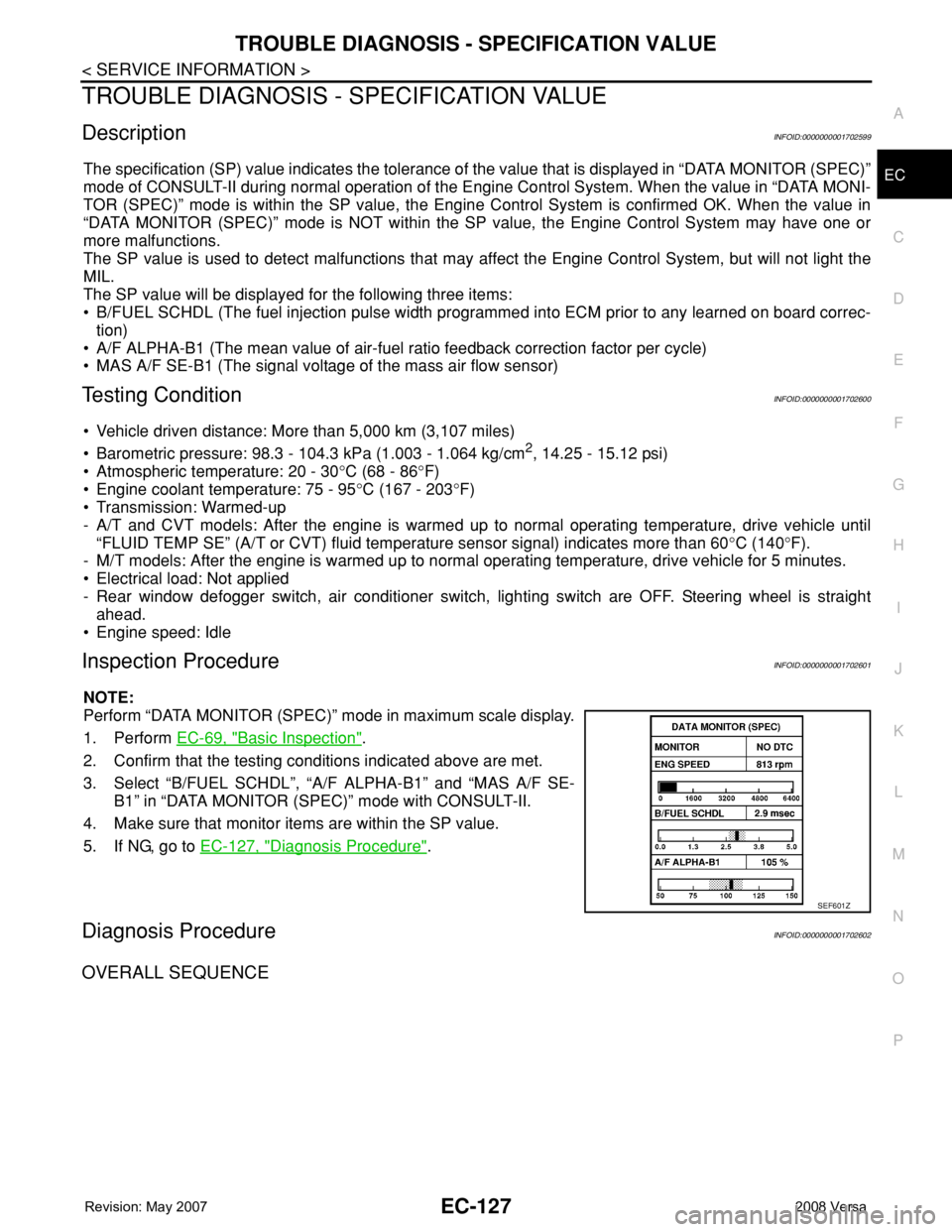
The specification (SP) value indicates the tolerance of the value that is displayed in “DATA MONITOR (SPEC)”
mode of CONSULT-II during normal operation of the Engine Control System. When the value in “DATA MONI-
TOR (SPEC)” mode is within the SP value, the Engine Control System is confirmed OK. When the value in
“DATA MONITOR (SPEC)” mode is NOT within the SP value, the Engine Control System may have one or
more malfunctions.
The SP value is used to detect malfunctions that may affect the Engine Control System, but will not light the
MIL.
The SP value will be displayed for the following three items:
• B/FUEL SCHDL (The fuel injection pulse width programmed into ECM prior to any learned on board correc-
tion)
• A/F ALPHA-B1 (The mean value of air-fuel ratio feedback correction factor per cycle)
• MAS A/F SE-B1 (The signal voltage of the mass air flow sensor)
Testing ConditionINFOID:0000000001702600
• Vehicle driven distance: More than 5,000 km (3,107 miles)
• Barometric pressure: 98.3 - 104.3 kPa (1.003 - 1.064 kg/cm
2, 14.25 - 15.12 psi)
• Atmospheric temperature: 20 - 30°C (68 - 86°F)
• Engine coolant temperature: 75 - 95°C (167 - 203°F)
• Transmission: Warmed-up
- A/T and CVT models: After the engine is warmed up to normal operating temperature, drive vehicle until
“FLUID TEMP SE” (A/T or CVT) fluid temperature sensor signal) indicates more than 60°C (140°F).
- M/T models: After the engine is warmed up to normal operating temperature, drive vehicle for 5 minutes.
• Electrical load: Not applied
- Rear window defogger switch, air conditioner switch, lighting switch are OFF. Steering wheel is straight
ahead.
• Engine speed: Idle
Inspection ProcedureINFOID:0000000001702601
NOTE:
Perform “DATA MONITOR (SPEC)” mode in maximum scale display.
1. Perform EC-69, "
Basic Inspection".
2. Confirm that the testing conditions indicated above are met.
3. Select “B/FUEL SCHDL”, “A/F ALPHA-B1” and “MAS A/F SE-
B1” in “DATA MONITOR (SPEC)” mode with CONSULT-II.
4. Make sure that monitor items are within the SP value.
5. If NG, go to EC-127, "
Diagnosis Procedure".
Diagnosis ProcedureINFOID:0000000001702602
OVERALL SEQUENCE
SEF601Z
Page 1388 of 2771

EC-314
< SERVICE INFORMATION >
DTC P0441 EVAP CONTROL SYSTEM
1. Start engine and warm it up to normal operating temperature.
2. Turn ignition switch OFF and wait at least 10 seconds.
3. Start engine and let it idle for at least 70 seconds.
4. Select “PURG FLOW P0441” of “EVAPORATIVE SYSTEM” in “DTC CONFIRMATION” mode with CON-
SULT-II.
5. Touch “START”.
If “COMPLETED” is displayed, go to step 7.
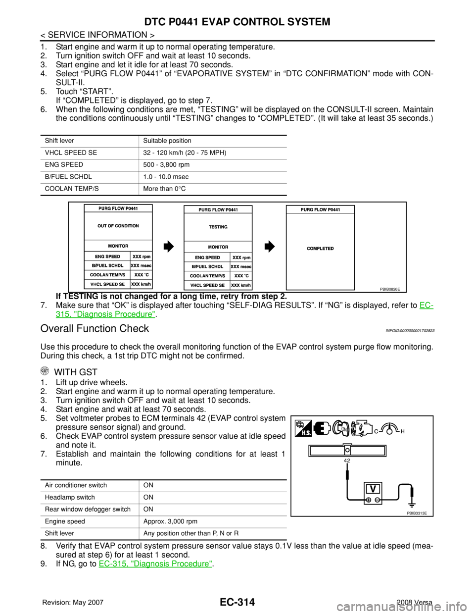
6. When the following conditions are met, “TESTING” will be displayed on the CONSULT-II screen. Maintain
the conditions continuously until “TESTING” changes to “COMPLETED”. (It will take at least 35 seconds.)
If TESTING is not changed for a long time, retry from step 2.
7. Make sure that “OK” is displayed after touching “SELF-DIAG RESULTS”. If “NG” is displayed, refer to EC-
315, "Diagnosis Procedure".
Overall Function CheckINFOID:0000000001702823
Use this procedure to check the overall monitoring function of the EVAP control system purge flow monitoring.
During this check, a 1st trip DTC might not be confirmed.
WITH GST
1. Lift up drive wheels.
2. Start engine and warm it up to normal operating temperature.
3. Turn ignition switch OFF and wait at least 10 seconds.
4. Start engine and wait at least 70 seconds.
5. Set voltmeter probes to ECM terminals 42 (EVAP control system
pressure sensor signal) and ground.
6. Check EVAP control system pressure sensor value at idle speed
and note it.
7. Establish and maintain the following conditions for at least 1
minute.
8. Verify that EVAP control system pressure sensor value stays 0.1V less than the value at idle speed (mea-
sured at step 6) for at least 1 second.
9. If NG, go to EC-315, "
Diagnosis Procedure".
Shift lever Suitable position
VHCL SPEED SE 32 - 120 km/h (20 - 75 MPH)
ENG SPEED 500 - 3,800 rpm
B/FUEL SCHDL 1.0 - 10.0 msec
COOLAN TEMP/S More than 0°C
PBIB0826E
Air conditioner switch ON
Headlamp switch ON
Rear window defogger switch ON
Engine speed Approx. 3,000 rpm
Shift lever Any position other than P, N or R
PBIB3313E
Page 1593 of 2771

ELECTRICAL LOAD SIGNAL
EC-519
< SERVICE INFORMATION >
C
D
E
F
G
H
I
J
K
L
MA
EC
N
P O
ELECTRICAL LOAD SIGNAL
CONSULT-II Reference Value in Data Monitor ModeINFOID:0000000001703057
Specification data are reference values.
Diagnosis ProcedureINFOID:0000000001703058
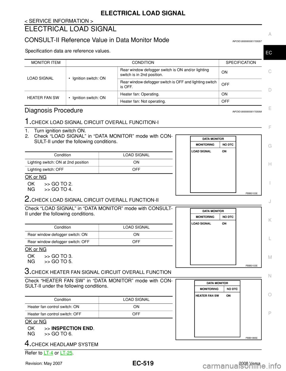
1.CHECK LOAD SIGNAL CIRCUIT OVERALL FUNCITION-I
1. Turn ignition switch ON.
2. Check “LOAD SIGNAL” in “DATA MONITOR” mode with CON-
SULT-II under the following conditions.
OK or NG
OK >> GO TO 2.
NG >> GO TO 4.
2.CHECK LOAD SIGNAL CIRCUIT OVERALL FUNCTION-II
Check “LOAD SIGNAL” in “DATA MONITOR” mode with CONSULT-
II under the following conditions.
OK or NG
OK >> GO TO 3.
NG >> GO TO 5.
3.CHECK HEATER FAN SIGNAL CIRCUIT OVERALL FUNCTION
Check “HEATER FAN SW” in “DATA MONITOR” mode with CON-
SULT-II under the following conditions.
OK or NG
OK >>INSPECTION END.
NG >> GO TO 6.
4.CHECK HEADLAMP SYSTEM
Refer to LT- 4
or LT- 2 5.
MONITOR ITEM CONDITION SPECIFICATION
LOAD SIGNAL • Ignition switch: ONRear window defogger switch is ON and/or lighting
switch is in 2nd position.ON
Rear window defogger switch is OFF and lighting switch
is OFF.OFF
HEATER FAN SW • Ignition switch: ONHeater fan: Operating. ON
Heater fan: Not operating. OFF
Condition LOAD SIGNAL
Lighting switch: ON at 2nd position ON
Lighting switch: OFF OFF
PBIB0103E
Condition LOAD SIGNAL
Rear window defogger switch: ON ON
Rear window defogger switch: OFF OFF
PBIB0103E
Condition LOAD SIGNAL
Heater fan control switch: ON ON
Heater fan control switch: OFF OFF
PBIB1995E
Page 1594 of 2771

EC-520
< SERVICE INFORMATION >
ELECTRICAL LOAD SIGNAL
>>INSPECTION END
5.CHECK REAR WINDOW DEFOGGER SYSTEM
Refer to GW-49
.
>>INSPECTION END
6.CHECK HEATER FAN CONTROL SYSTEM
Refer to MTC-22
.
>>INSPECTION END
Page 1622 of 2771

EC-548
< SERVICE INFORMATION >
SERVICE DATA AND SPECIFICATIONS (SDS)
SERVICE DATA AND SPECIFICATIONS (SDS)
Fuel PressureINFOID:0000000001703081
Idle Speed and Ignition TimingINFOID:0000000001703082
*: Under the following conditions:
• Air conditioner switch: OFF
• Electric load: OFF (Lights, heater fan & rear window defogger)
• Steering wheel: Kept in straight-ahead position
Calculated Load ValueINFOID:0000000001703083
Mass Air Flow SensorINFOID:0000000001703084
*: Engine is warmed up to normal operating temperature and running under no load.
Intake Air Temperature SensorINFOID:0000000001703085
Engine Coolant Temperature SensorINFOID:0000000001703086
Fuel pressure at idle
Approximately 350 kPa (3.57 kg/cm2, 51 psi)
Target idle speedA/T No load* (in P or N position)
700 ± 50 rpm CVT No load* (In P or N position)
M/T No load* (in Neutral position)
Air conditioner: ONA/T In P or N position
850 rpm or more CVT In P or N position
M/T In Neutral position
Ignition timingA/T In P or N position
13 ± 5° BTDC CVT In P or N position
M/T In Neutral position
Calculated load value% (Using CONSULT-II or GST)
At idle10 - 35
At 2,500 rpm10 - 35
Supply voltageBattery voltage (11 - 14V)
Output voltage at idle1.0 - 1.3*V
Mass air flow (Using CONSULT-II or GST)1.0 - 4.0 g·m/sec at idle*
2.0 - 10.0 g·m/sec at 2,500 rpm*
Temperature °C (°F) Resistance kΩ
25 (77)1.800 - 2.200
Temperature °C (°F) Resistance kΩ
20 (68)2.1 - 2.9
50 (122)0.68 - 1.00
90 (194)0.236 - 0.260
Page 1878 of 2771

SERVICE INFORMATION FOR ELECTRICAL INCIDENT
GI-27
< SERVICE INFORMATION >
C
D
E
F
G
H
I
J
K
L
MB
GI
N
O
P
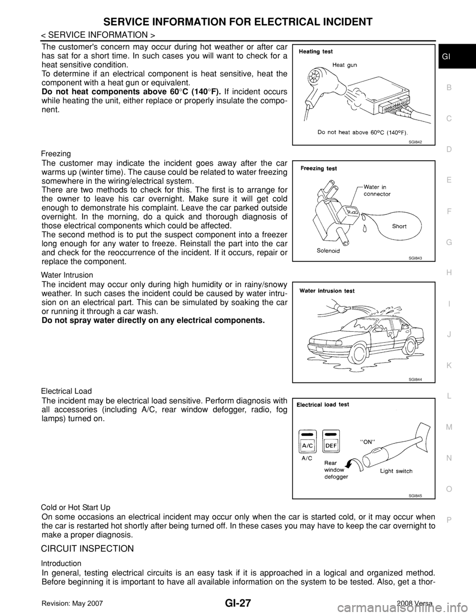
The customer's concern may occur during hot weather or after car
has sat for a short time. In such cases you will want to check for a
heat sensitive condition.
To determine if an electrical component is heat sensitive, heat the
component with a heat gun or equivalent.
Do not heat components above 60°C (140°F). If incident occurs
while heating the unit, either replace or properly insulate the compo-
nent.
Freezing
The customer may indicate the incident goes away after the car
warms up (winter time). The cause could be related to water freezing
somewhere in the wiring/electrical system.
There are two methods to check for this. The first is to arrange for
the owner to leave his car overnight. Make sure it will get cold
enough to demonstrate his complaint. Leave the car parked outside
overnight. In the morning, do a quick and thorough diagnosis of
those electrical components which could be affected.
The second method is to put the suspect component into a freezer
long enough for any water to freeze. Reinstall the part into the car
and check for the reoccurrence of the incident. If it occurs, repair or
replace the component.
Water Intrusion
The incident may occur only during high humidity or in rainy/snowy
weather. In such cases the incident could be caused by water intru-
sion on an electrical part. This can be simulated by soaking the car
or running it through a car wash.
Do not spray water directly on any electrical components.
Electrical Load
The incident may be electrical load sensitive. Perform diagnosis with
all accessories (including A/C, rear window defogger, radio, fog
lamps) turned on.
Cold or Hot Start Up
On some occasions an electrical incident may occur only when the car is started cold, or it may occur when
the car is restarted hot shortly after being turned off. In these cases you may have to keep the car overnight to
make a proper diagnosis.
CIRCUIT INSPECTION
Introduction
In general, testing electrical circuits is an easy task if it is approached in a logical and organized method.
Before beginning it is important to have all available information on the system to be tested. Also, get a thor-
SGI842
SGI843
SGI844
SGI845