2008 NISSAN TIIDA indicator
[x] Cancel search: indicatorPage 1592 of 2771
EC-518
< SERVICE INFORMATION >
ASCD INDICATOR
OK or NG
OK >>INSPECTION END
NG >> GO TO 2.
2.CHECK DTC
Check that DTC U1000 or U1001 is not displayed.
Ye s o r N o
Yes >> Perform trouble diagnoses for DTC U1000, U1001, refer to EC-143.
No >> GO TO 3.
3.CHECK COMBINATION METER OPERATION
Does combination meter operate normally?
Ye s o r N o
Ye s > > G O T O 4 .
No >> Check combination meter circuit. Refer to DI-4
.
4.CHECK INTERMITTENT INCIDENT
Refer to EC-136
.
>>INSPECTION END
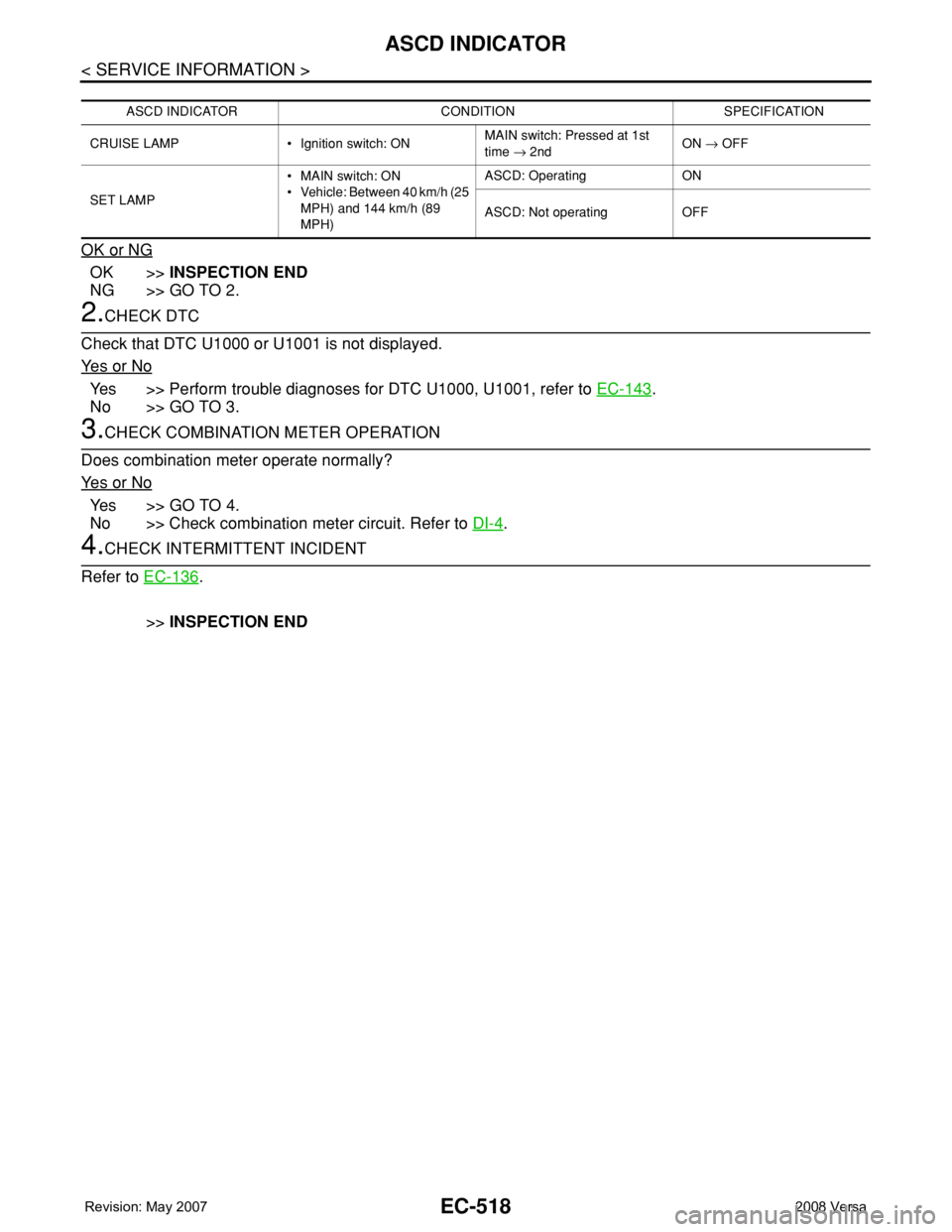
ASCD INDICATOR CONDITION SPECIFICATION
CRUISE LAMP • Ignition switch: ONMAIN switch: Pressed at 1st
time → 2ndON → OFF
SET LAMP•MAIN switch: ON
• Vehicle: Between 40 km/h (25
MPH) and 144 km/h (89
MPH)ASCD: Operating ON
ASCD: Not operating OFF
Page 1690 of 2771
DRIVE BELTS
EM-13
< SERVICE INFORMATION >
C
D
E
F
G
H
I
J
K
L
MA
EM
N
P O
DRIVE BELTS
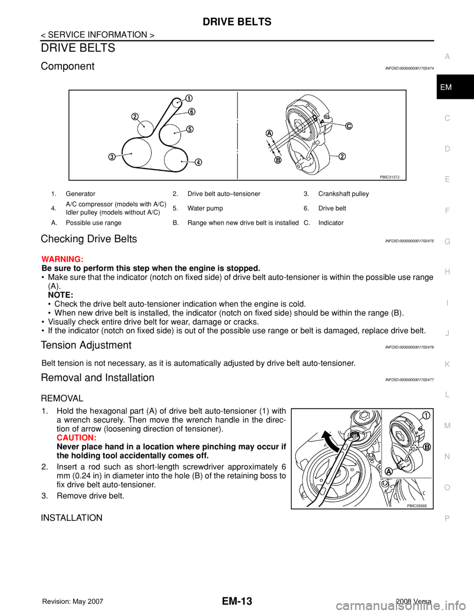
ComponentINFOID:0000000001702474
Checking Drive BeltsINFOID:0000000001702475
WARNING:
Be sure to perform this step when the engine is stopped.
• Make sure that the indicator (notch on fixed side) of drive belt auto-tensioner is within the possible use range
(A).
NOTE:
• Check the drive belt auto-tensioner indication when the engine is cold.
• When new drive belt is installed, the indicator (notch on fixed side) should be within the range (B).
• Visually check entire drive belt for wear, damage or cracks.
• If the indicator (notch on fixed side) is out of the possible use range or belt is damaged, replace drive belt.
Tension AdjustmentINFOID:0000000001702476
Belt tension is not necessary, as it is automatically adjusted by drive belt auto-tensioner.
Removal and InstallationINFOID:0000000001702477
REMOVAL
1. Hold the hexagonal part (A) of drive belt auto-tensioner (1) with
a wrench securely. Then move the wrench handle in the direc-
tion of arrow (loosening direction of tensioner).
CAUTION:
Never place hand in a location where pinching may occur if
the holding tool accidentally comes off.
2. Insert a rod such as short-length screwdriver approximately 6
mm (0.24 in) in diameter into the hole (B) of the retaining boss to
fix drive belt auto-tensioner.
3. Remove drive belt.
INSTALLATION
1. Generator 2. Drive belt auto–tensioner 3. Crankshaft pulley
4.A/C compressor (models with A/C)
Idler pulley (models without A/C)5. Water pump 6. Drive belt
A. Possible use range B. Range when new drive belt is installed C. Indicator
PBIC3137J
PBIC3936E
Page 1691 of 2771
EM-14
< SERVICE INFORMATION >
DRIVE BELTS
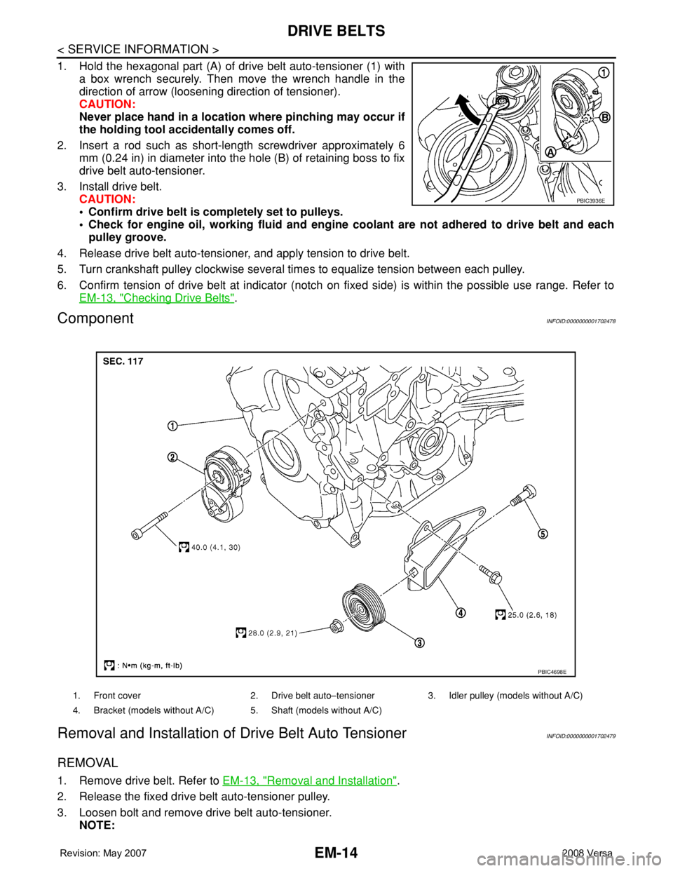
1. Hold the hexagonal part (A) of drive belt auto-tensioner (1) with
a box wrench securely. Then move the wrench handle in the
direction of arrow (loosening direction of tensioner).
CAUTION:
Never place hand in a location where pinching may occur if
the holding tool accidentally comes off.
2. Insert a rod such as short-length screwdriver approximately 6
mm (0.24 in) in diameter into the hole (B) of retaining boss to fix
drive belt auto-tensioner.
3. Install drive belt.
CAUTION:
• Confirm drive belt is completely set to pulleys.
• Check for engine oil, working fluid and engine coolant are not adhered to drive belt and each
pulley groove.
4. Release drive belt auto-tensioner, and apply tension to drive belt.
5. Turn crankshaft pulley clockwise several times to equalize tension between each pulley.
6. Confirm tension of drive belt at indicator (notch on fixed side) is within the possible use range. Refer to
EM-13, "
Checking Drive Belts".
ComponentINFOID:0000000001702478
Removal and Installation of Drive Belt Auto TensionerINFOID:0000000001702479
REMOVAL
1. Remove drive belt. Refer to EM-13, "Removal and Installation".
2. Release the fixed drive belt auto-tensioner pulley.
3. Loosen bolt and remove drive belt auto-tensioner.
NOTE:
PBIC3936E
1. Front cover 2. Drive belt auto–tensioner 3. Idler pulley (models without A/C)
4. Bracket (models without A/C) 5. Shaft (models without A/C)
PBIC4698E
Page 1715 of 2771
EM-38
< SERVICE INFORMATION >
TIMING CHAIN
Removal and Installation
INFOID:0000000001844926
CAUTION:
The rotating direction indicated in the text indicates all directions seen from the engine front.
REMOVAL
1. Remove front RH wheel. Refer to WT-6, "Rotation".
2. Remove front fender protector (RH). Refer to EI-23, "
Removal and Installation".
3. Drain engine oil. Refer to LU-7, "
Changing Engine Oil".
NOTE:
Perform this step when engine is cold.
4. Remove the following parts.
• Rocker cover: Refer to EM-30, "
Component".
• Drive belt: Refer to EM-13, "
Removal and Installation".
• Water pump pulley: Refer to CO-16, "
Component".
• Ground cable (between engine bracket (RH) and radiator core support)
5. Support the bottom surface of engine using a transmission jack, and then remove the engine bracket and
insulator (RH). Refer to EM-72, "
Component".
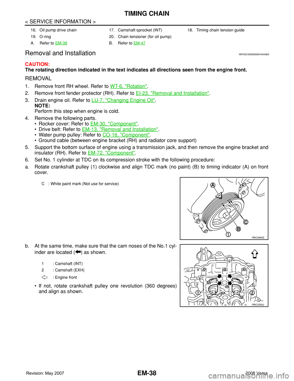
6. Set No. 1 cylinder at TDC on its compression stroke with the following procedure:
a. Rotate crankshaft pulley (1) clockwise and align TDC mark (no paint) (B) to timing indicator (A) on front
cover.
b. At the same time, make sure that the cam noses of the No.1 cyl-
inder are located ( ) as shown.
• If not, rotate crankshaft pulley one revolution (360 degrees)
and align as shown.
16. Oil pump drive chain 17. Camshaft sprocket (INT) 18. Timing chain tension guide
19. O-ring 20. Chain tensioner (for oil pump)
A. Refer to EM-38
B. Refer to EM-47
C : White paint mark (Not use for service)
PBIC3960E
1 : Camshaft (INT)
2 : Camshaft (EXH)
: Engine front
PBIC3359J
Page 1726 of 2771
CAMSHAFT
EM-49
< SERVICE INFORMATION >
C
D
E
F
G
H
I
J
K
L
MA
EM
N
P O
13. Remove valve lifters.
NOTE:
Identify installed positions, and store them without mixing them up.
INSPECTION AFTER REMOVAL
Camshaft Runout
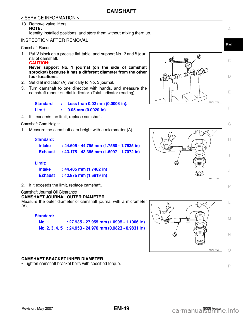
1. Put V-block on a precise flat table, and support No. 2 and 5 jour-
nal of camshaft.
CAUTION:
Never support No. 1 journal (on the side of camshaft
sprocket) because it has a different diameter from the other
four locations.
2. Set dial indicator (A) vertically to No. 3 journal.
3. Turn camshaft to one direction with hands, and measure the
camshaft runout on dial indicator. (Total indicator reading)
4. If it exceeds the limit, replace camshaft.
Camshaft Cam Height
1. Measure the camshaft cam height with a micrometer (A).
2. If it exceeds the limit, replace camshaft.
Camshaft Journal Oil Clearance
CAMSHAFT JOURNAL OUTER DIAMETER
Measure the outer diameter of camshaft journal with a micrometer
(A).
CAMSHAFT BRACKET INNER DIAMETER
• Tighten camshaft bracket bolts with specified torque. Standard : Less than 0.02 mm (0.0008 in).
Limit : 0.05 mm (0.0020 in)
PBIC3177J
Standard:
Intake : 44.605 - 44.795 mm (1.7560 - 1.7635 in)
Exhaust : 43.175 - 43.365 mm (1.6997 - 1.7072 in)
Limit:
Intake : 44.405 mm (1.7482 in)
Exhaust : 42.975 mm (1.6919 in)
PBIC3178J
Standard:
No. 1 : 27.935 - 27.955 mm (1.0998 - 1.1006 in)
No. 2, 3, 4, 5 : 24.950 - 24.970 mm (0.9823 - 0.9831 in)
PBIC3179J
Page 1727 of 2771
EM-50
< SERVICE INFORMATION >
CAMSHAFT
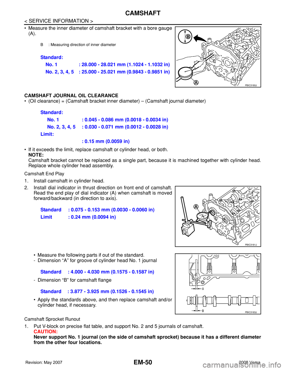
• Measure the inner diameter of camshaft bracket with a bore gauge
(A).
CAMSHAFT JOURNAL OIL CLEARANCE
• (Oil clearance) = (Camshaft bracket inner diameter) – (Camshaft journal diameter)
• If it exceeds the limit, replace camshaft or cylinder head, or both.
NOTE:
Camshaft bracket cannot be replaced as a single part, because it is machined together with cylinder head.
Replace whole cylinder head assembly.
Camshaft End Play
1. Install camshaft in cylinder head.
2. Install dial indicator in thrust direction on front end of camshaft.
Read the end play of dial indicator (A) when camshaft is moved
forward/backward (in direction to axis).
• Measure the following parts if out of the standard.
- Dimension “A” for groove of cylinder head No. 1 journal
- Dimension “B” for camshaft flange
• Apply the standards above, and then replace camshaft and/or
cylinder head, if necessary.
Camshaft Sprocket Runout
1. Put V-block on precise flat table, and support No. 2 and 5 journals of camshaft.
CAUTION:
Never support No. 1 journal (on the side of camshaft sprocket) because it has a different diameter
from the other four locations.
B : Measuring direction of inner diameter
Standard:
No. 1 : 28.000 - 28.021 mm (1.1024 - 1.1032 in)
No. 2, 3, 4, 5 : 25.000 - 25.021 mm (0.9843 - 0.9851 in)
PBIC3180J
Standard:
No. 1 : 0.045 - 0.086 mm (0.0018 - 0.0034 in)
No. 2, 3, 4, 5 : 0.030 - 0.071 mm (0.0012 - 0.0028 in)
Limit:
: 0.15 mm (0.0059 in)
Standard : 0.075 - 0.153 mm (0.0030 - 0.0060 in)
Limit : 0.24 mm (0.0094 in)
PBIC3181J
Standard : 4.000 - 4.030 mm (0.1575 - 0.1587 in)
Standard : 3.877 - 3.925 mm (0.1526 - 0.1545 in)
PBIC3183J
Page 1728 of 2771
CAMSHAFT
EM-51
< SERVICE INFORMATION >
C
D
E
F
G
H
I
J
K
L
MA
EM
N
P O
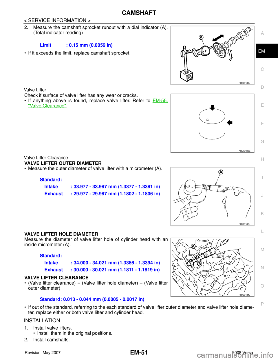
2. Measure the camshaft sprocket runout with a dial indicator (A).
(Total indicator reading)
• If it exceeds the limit, replace camshaft sprocket.
Valve Lifter
Check if surface of valve lifter has any wear or cracks.
• If anything above is found, replace valve lifter. Refer to EM-55,
"Valve Clearance".
Valve Lifter Clearance
VALVE LIFTER OUTER DIAMETER
• Measure the outer diameter of valve lifter with a micrometer (A).
VALVE LIFTER HOLE DIAMETER
Measure the diameter of valve lifter hole of cylinder head with an
inside micrometer (A).
VALVE LIFTER CLEARANCE
• (Valve lifter clearance) = (Valve lifter hole diameter) – (Valve lifter
outer diameter)
• If out of the standard, referring to the each standard of valve lifter outer diameter and valve lifter hole diame-
ter, replace either or both valve lifter and cylinder head.
INSTALLATION
1. Install valve lifters.
• Install them in the original positions.
2. Install camshafts.Limit : 0.15 mm (0.0059 in)
PBIC3182J
KBIA0182E
Standard:
Intake : 33.977 - 33.987 mm (1.3377 - 1.3381 in)
Exhaust : 29.977 - 29.987 mm (1.1802 - 1.1806 in)
PBIC3185J
Standard:
Intake : 34.000 - 34.021 mm (1.3386 - 1.3394 in)
Exhaust : 30.000 - 30.021 mm (1.1811 - 1.1819 in)
Standard: 0.013 - 0.044 mm (0.0005 - 0.0017 in)
PBIC3184J
Page 1732 of 2771
CAMSHAFT
EM-55
< SERVICE INFORMATION >
C
D
E
F
G
H
I
J
K
L
MA
EM
N
P O
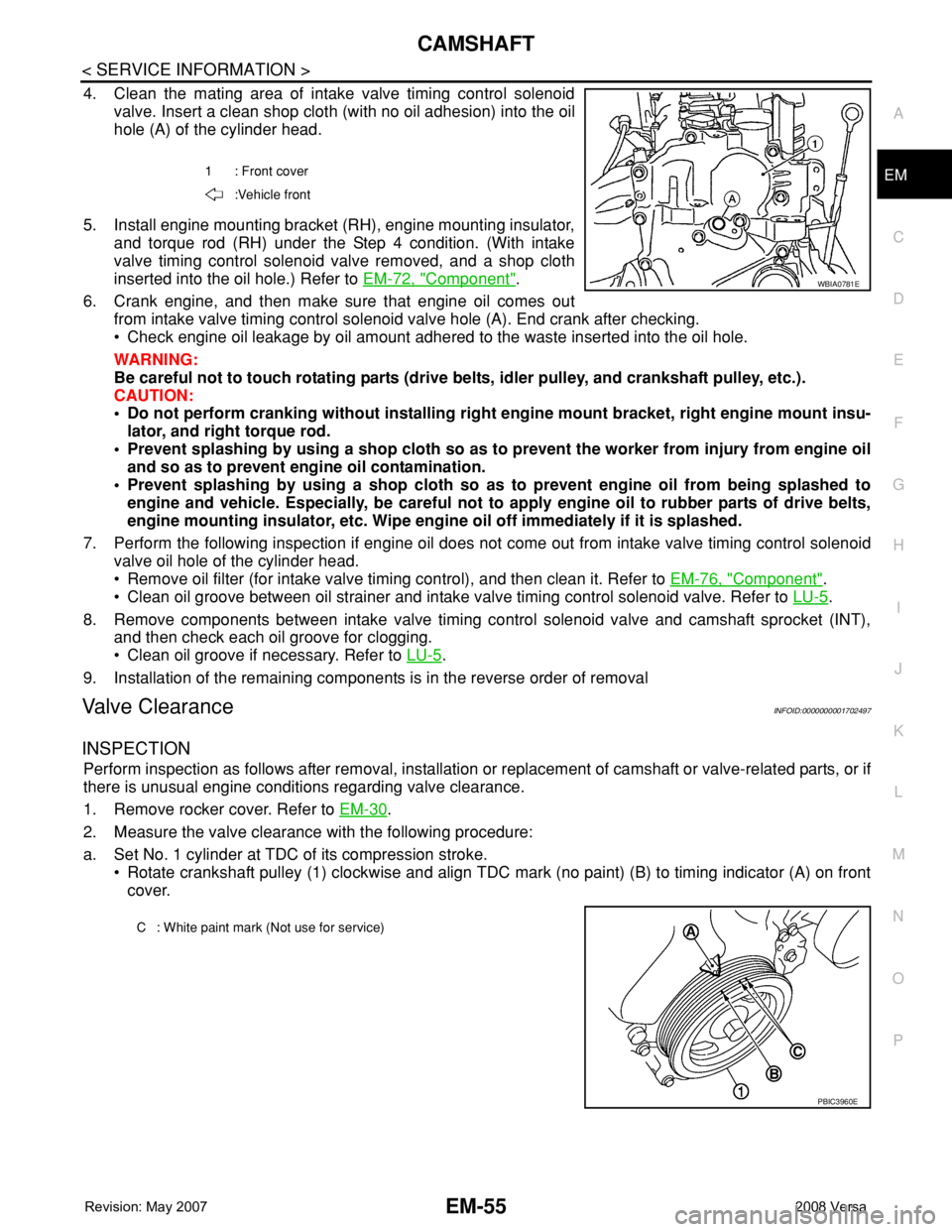
4. Clean the mating area of intake valve timing control solenoid
valve. Insert a clean shop cloth (with no oil adhesion) into the oil
hole (A) of the cylinder head.
5. Install engine mounting bracket (RH), engine mounting insulator,
and torque rod (RH) under the Step 4 condition. (With intake
valve timing control solenoid valve removed, and a shop cloth
inserted into the oil hole.) Refer to EM-72, "
Component".
6. Crank engine, and then make sure that engine oil comes out
from intake valve timing control solenoid valve hole (A). End crank after checking.
• Check engine oil leakage by oil amount adhered to the waste inserted into the oil hole.
WARNING:
Be careful not to touch rotating parts (drive belts, idler pulley, and crankshaft pulley, etc.).
CAUTION:
• Do not perform cranking without installing right engine mount bracket, right engine mount insu-
lator, and right torque rod.
• Prevent splashing by using a shop cloth so as to prevent the worker from injury from engine oil
and so as to prevent engine oil contamination.
• Prevent splashing by using a shop cloth so as to prevent engine oil from being splashed to
engine and vehicle. Especially, be careful not to apply engine oil to rubber parts of drive belts,
engine mounting insulator, etc. Wipe engine oil off immediately if it is splashed.
7. Perform the following inspection if engine oil does not come out from intake valve timing control solenoid
valve oil hole of the cylinder head.
• Remove oil filter (for intake valve timing control), and then clean it. Refer to EM-76, "
Component".
• Clean oil groove between oil strainer and intake valve timing control solenoid valve. Refer to LU-5
.
8. Remove components between intake valve timing control solenoid valve and camshaft sprocket (INT),
and then check each oil groove for clogging.
• Clean oil groove if necessary. Refer to LU-5
.
9. Installation of the remaining components is in the reverse order of removal
Valve ClearanceINFOID:0000000001702497
INSPECTION
Perform inspection as follows after removal, installation or replacement of camshaft or valve-related parts, or if
there is unusual engine conditions regarding valve clearance.
1. Remove rocker cover. Refer to EM-30
.
2. Measure the valve clearance with the following procedure:
a. Set No. 1 cylinder at TDC of its compression stroke.
• Rotate crankshaft pulley (1) clockwise and align TDC mark (no paint) (B) to timing indicator (A) on front
cover.
1 : Front cover
:Vehicle front
WBIA0781E
C : White paint mark (Not use for service)
PBIC3960E