2008 NISSAN TIIDA Electrical
[x] Cancel search: ElectricalPage 1929 of 2771
GW-28
< SERVICE INFORMATION >
POWER WINDOW SYSTEM
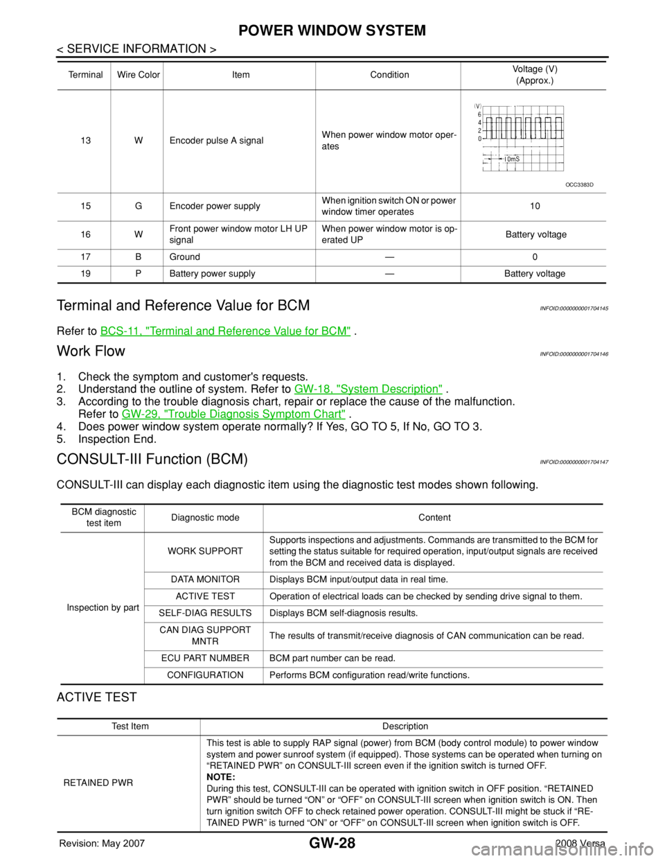
Terminal and Reference Value for BCM
INFOID:0000000001704145
Refer to BCS-11, "Terminal and Reference Value for BCM" .
Work FlowINFOID:0000000001704146
1. Check the symptom and customer's requests.
2. Understand the outline of system. Refer to GW-18, "
System Description" .
3. According to the trouble diagnosis chart, repair or replace the cause of the malfunction.
Refer to GW-29, "
Trouble Diagnosis Symptom Chart" .
4. Does power window system operate normally? If Yes, GO TO 5, If No, GO TO 3.
5. Inspection End.
CONSULT-III Function (BCM)INFOID:0000000001704147
CONSULT-III can display each diagnostic item using the diagnostic test modes shown following.
ACTIVE TEST
13 W Encoder pulse A signalWhen power window motor oper-
ates
15 G Encoder power supplyWhen ignition switch ON or power
window timer operates10
16 WFront power window motor LH UP
signalWhen power window motor is op-
erated UP Battery voltage
17 B Ground — 0
19 P Battery power supply — Battery voltage Terminal Wire Color Item ConditionVoltage (V)
(Approx.)
OCC3383D
BCM diagnostic
test itemDiagnostic mode Content
Inspection by partWORK SUPPORTSupports inspections and adjustments. Commands are transmitted to the BCM for
setting the status suitable for required operation, input/output signals are received
from the BCM and received data is displayed.
DATA MONITOR Displays BCM input/output data in real time.
ACTIVE TEST Operation of electrical loads can be checked by sending drive signal to them.
SELF-DIAG RESULTS Displays BCM self-diagnosis results.
CAN DIAG SUPPORT
MNTRThe results of transmit/receive diagnosis of CAN communication can be read.
ECU PART NUMBER BCM part number can be read.
CONFIGURATION Performs BCM configuration read/write functions.
Te s t I t e m D e s c r i p t i o n
RETAINED PWRThis test is able to supply RAP signal (power) from BCM (body control module) to power window
system and power sunroof system (if equipped). Those systems can be operated when turning on
“RETAINED PWR” on CONSULT-III screen even if the ignition switch is turned OFF.
NOTE:
During this test, CONSULT-III can be operated with ignition switch in OFF position. “RETAINED
PWR” should be turned “ON” or “OFF” on CONSULT-III screen when ignition switch is ON. Then
turn ignition switch OFF to check retained power operation. CONSULT-III might be stuck if “RE-
TAINED PWR” is turned “ON” or “OFF” on CONSULT-III screen when ignition switch is OFF.
Page 1943 of 2771
GW-42
< SERVICE INFORMATION >
FRONT DOOR GLASS AND REGULATOR
FRONT DOOR GLASS AND REGULATOR
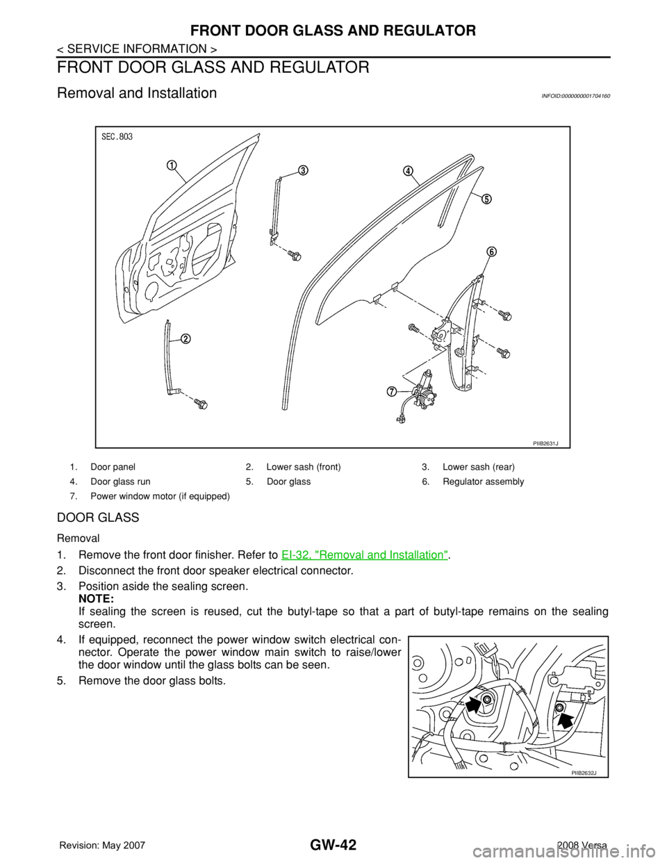
Removal and InstallationINFOID:0000000001704160
DOOR GLASS
Removal
1. Remove the front door finisher. Refer to EI-32, "Removal and Installation".
2. Disconnect the front door speaker electrical connector.
3. Position aside the sealing screen.
NOTE:
If sealing the screen is reused, cut the butyl-tape so that a part of butyl-tape remains on the sealing
screen.
4. If equipped, reconnect the power window switch electrical con-
nector. Operate the power window main switch to raise/lower
the door window until the glass bolts can be seen.
5. Remove the door glass bolts.
1. Door panel 2. Lower sash (front) 3. Lower sash (rear)
4. Door glass run 5. Door glass 6. Regulator assembly
7. Power window motor (if equipped)
PIIB2631J
PIIB2632J
Page 1944 of 2771
FRONT DOOR GLASS AND REGULATOR
GW-43
< SERVICE INFORMATION >
C
D
E
F
G
H
J
K
L
MA
B
GW
N
O
P
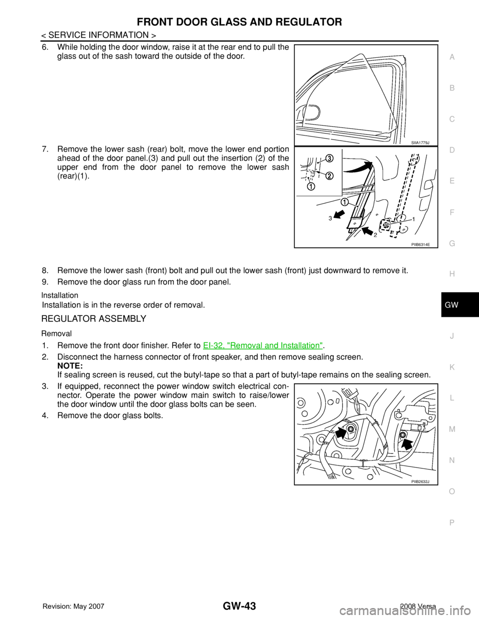
6. While holding the door window, raise it at the rear end to pull the
glass out of the sash toward the outside of the door.
7. Remove the lower sash (rear) bolt, move the lower end portion
ahead of the door panel.(3) and pull out the insertion (2) of the
upper end from the door panel to remove the lower sash
(rear)(1).
8. Remove the lower sash (front) bolt and pull out the lower sash (front) just downward to remove it.
9. Remove the door glass run from the door panel.
Installation
Installation is in the reverse order of removal.
REGULATOR ASSEMBLY
Removal
1. Remove the front door finisher. Refer to EI-32, "Removal and Installation".
2. Disconnect the harness connector of front speaker, and then remove sealing screen.
NOTE:
If sealing screen is reused, cut the butyl-tape so that a part of butyl-tape remains on the sealing screen.
3. If equipped, reconnect the power window switch electrical con-
nector. Operate the power window main switch to raise/lower
the door window until the door glass bolts can be seen.
4. Remove the door glass bolts.
SIIA1779J
PIIB6314E
PIIB2632J
Page 1954 of 2771
REAR WINDOW DEFOGGER
GW-53
< SERVICE INFORMATION >
C
D
E
F
G
H
J
K
L
MA
B
GW
N
O
P
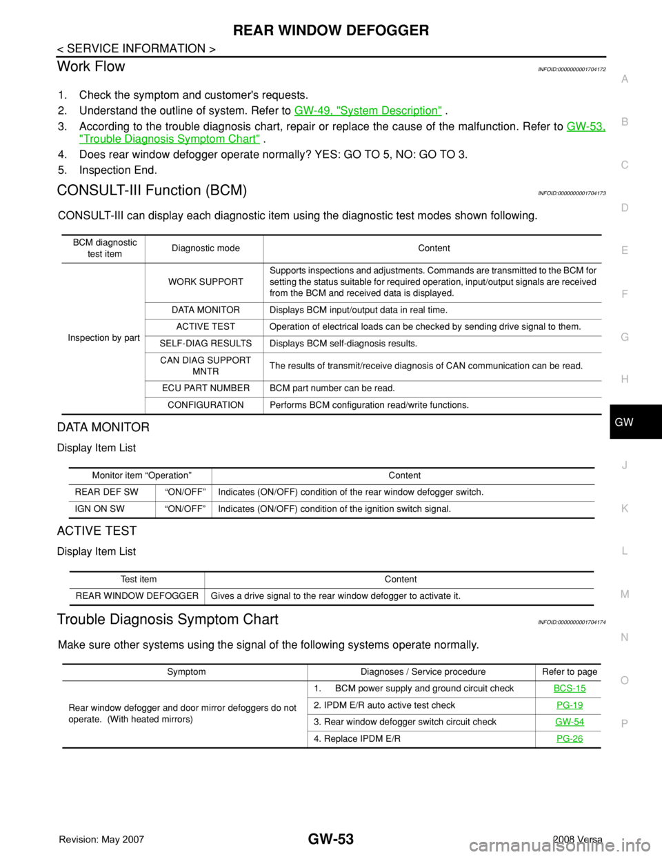
Work FlowINFOID:0000000001704172
1. Check the symptom and customer's requests.
2. Understand the outline of system. Refer to GW-49, "
System Description" .
3. According to the trouble diagnosis chart, repair or replace the cause of the malfunction. Refer to GW-53,
"Trouble Diagnosis Symptom Chart" .
4. Does rear window defogger operate normally? YES: GO TO 5, NO: GO TO 3.
5. Inspection End.
CONSULT-III Function (BCM)INFOID:0000000001704173
CONSULT-III can display each diagnostic item using the diagnostic test modes shown following.
DATA MONITOR
Display Item List
ACTIVE TEST
Display Item List
Trouble Diagnosis Symptom ChartINFOID:0000000001704174
Make sure other systems using the signal of the following systems operate normally.
BCM diagnostic
test itemDiagnostic mode Content
Inspection by partWORK SUPPORTSupports inspections and adjustments. Commands are transmitted to the BCM for
setting the status suitable for required operation, input/output signals are received
from the BCM and received data is displayed.
DATA MONITOR Displays BCM input/output data in real time.
ACTIVE TEST Operation of electrical loads can be checked by sending drive signal to them.
SELF-DIAG RESULTS Displays BCM self-diagnosis results.
CAN DIAG SUPPORT
MNTRThe results of transmit/receive diagnosis of CAN communication can be read.
ECU PART NUMBER BCM part number can be read.
CONFIGURATION Performs BCM configuration read/write functions.
Monitor item “Operation” Content
REAR DEF SW “ON/OFF” Indicates (ON/OFF) condition of the rear window defogger switch.
IGN ON SW “ON/OFF” Indicates (ON/OFF) condition of the ignition switch signal.
Test item Content
REAR WINDOW DEFOGGER Gives a drive signal to the rear window defogger to activate it.
Symptom Diagnoses / Service procedure Refer to page
Rear window defogger and door mirror defoggers do not
operate. (With heated mirrors)1. BCM power supply and ground circuit checkBCS-15
2. IPDM E/R auto active test checkPG-19
3. Rear window defogger switch circuit checkGW-54
4. Replace IPDM E/RPG-26
Page 1968 of 2771
IP-2
< PRECAUTION >
PRECAUTIONS
PRECAUTION
PRECAUTIONS
Precaution for Supplemental Restraint System (SRS) "AIR BAG" and "SEAT BELT
PRE-TENSIONER"
INFOID:0000000001704244
The Supplemental Restraint System such as “AIR BAG” and “SEAT BELT PRE-TENSIONER”, used along
with a front seat belt, helps to reduce the risk or severity of injury to the driver and front passenger for certain
types of collision. This system includes seat belt switch inputs and dual stage front air bag modules. The SRS
system uses the seat belt switches to determine the front air bag deployment, and may only deploy one front
air bag, depending on the severity of a collision and whether the front occupants are belted or unbelted.
Information necessary to service the system safely is included in the SR and SB section of this Service Man-
ual.
WARNING:
• To avoid rendering the SRS inoperative, which could increase the risk of personal injury or death in
the event of a collision which would result in air bag inflation, all maintenance must be performed by
an authorized NISSAN/INFINITI dealer.
• Improper maintenance, including incorrect removal and installation of the SRS, can lead to personal
injury caused by unintentional activation of the system. For removal of Spiral Cable and Air Bag
Module, see the SR section.
• Do not use electrical test equipment on any circuit related to the SRS unless instructed to in this
Service Manual. SRS wiring harnesses can be identified by yellow and/or orange harnesses or har-
ness connectors.
PrecautionINFOID:0000000001704245
• Disconnect both battery terminals in advance.
• Disconnect air bag system line in advance.
• Never tamper with or force air bag lid open, as this may adversely affect air bag performance.
• Be careful not to scratch pad and other parts.
• When removing or disassembling any part, be careful not to damage or deform it. Protect parts which may
get in the way with cloth.
• When removing parts, protect parts by wrapping tools with vinyl or tape.
• Keep removed parts protected with cloth.
• If a clip is deformed or damaged, replace it.
• If an non-reusable part is removed, replace it with a new one.
• Tighten bolts and nuts firmly to the specified torque.
• After re-assembly has been completed, make sure each part functions correctly.
• Remove stains in the following way.
Water-soluble stains:
Dip a soft cloth in warm water, and then squeeze it tightly. After wiping the stain, wipe with a soft dry cloth.
Oil stain:
Dissolve a synthetic detergent in warm water (density of 2 to 3% or less), dip the cloth, then clean off the stain
with the cloth. Next, dip the cloth in fresh water and squeeze it tightly. Then clean off the detergent completely.
Then wipe the area with a soft dry cloth.
• Do not use any organic solvent, such as thinner or benzine.
Page 1971 of 2771
SQUEAK AND RATTLE TROUBLE DIAGNOSES
IP-5
< SYMPTOM DIAGNOSIS >
C
D
E
F
G
H
J
K
L
MA
B
IP
N
O
P
If possible, drive the vehicle with the customer until the noise is duplicated. Note any additional information on
the Diagnostic Worksheet regarding the conditions or location of the noise. This information can be used to
duplicate the same conditions when you confirm the repair.
If the noise can be duplicated easily during the test drive, to help identify the source of the noise, try to dupli-
cate the noise with the vehicle stopped by doing one or all of the following:
1. Close a door.
2. Tap or push/pull around the area where the noise appears to be coming from.
3. Rev the engine.
4. Use a floor jack to recreate vehicle “twist”.
5. At idle, apply engine load (electrical load, half-clutch on M/T model, drive position on A/T model).
6. Raise the vehicle on a hoist and hit a tire with a rubber hammer.
• Drive the vehicle and attempt to duplicate the conditions the customer states exist when the noise occurs.
• If it is difficult to duplicate the noise, drive the vehicle slowly on an undulating or rough road to stress the
vehicle body.
CHECK RELATED SERVICE BULLETINS
After verifying the customer concern or symptom, check ASIST for Technical Service Bulletins (TSBs) related
to that concern or symptom.
If a TSB relates to the symptom, follow the procedure to repair the noise.
LOCATE THE NOISE AND IDENTIFY THE ROOT CAUSE
1. Narrow down the noise to a general area. To help pinpoint the source of the noise, use a listening tool
(Chassis Ear: J-39570, Engine Ear: J-39565, and mechanics stethoscope).
2. Narrow down the noise to a more specific area and identify the cause of the noise by:
• Removing the components in the area that you suspect the noise is coming from.
Do not use too much force when removing clips and fasteners, otherwise clips and fasteners
can be broken or lost during the repair, resulting in the creation of new noise.
• Tapping or pushing/pulling the component that you suspect is causing the noise.
Do not tap or push/pull the component with excessive force, otherwise the noise will be elimi-
nated only temporarily.
• Feeling for a vibration with your hand by touching the component(s) that you suspect is (are) causing
the noise.
• Placing a piece of paper between components that you suspect are causing the noise.
• Looking for loose components and contact marks.
Refer to IP-6, "
Generic Squeak and Rattle Troubleshooting" .
REPAIR THE CAUSE
• If the cause is a loose component, tighten the component securely.
• If the cause is insufficient clearance between components:
- Separate components by repositioning or loosening and retightening the component, if possible.
- Insulate components with a suitable insulator such as urethane pads, foam blocks, felt cloth tape or ure-
thane tape. A NISSAN Squeak and Rattle Kit (J-43980) is available through your authorized NISSAN Parts
Department.
CAUTION:
Do not use excessive force as many components are constructed of plastic and may be damaged.
Always check with the Parts Department for the latest parts information.
The following materials are contained in the NISSAN Squeak and Rattle Kit (J-43980). Each item can be
ordered separately as needed.
URETHANE PADS [1.5 mm (0.059 in) thick]
Insulates connectors, harness, etc.
76268-9E005: 100 x 135 mm (3.94 x 5.31 in)/76884-71L01: 60 x 85 mm (2.36 x 3.35 in)/76884-71L02: 15 x 25
mm (0.59 x 0.98 in)
INSULATOR (Foam blocks)
Insulates components from contact. Can be used to fill space behind a panel.
73982-9E000: 45 mm (1.77 in) thick, 50 x 50 mm (1.97 x 1.97 in)/73982-50Y00: 10 mm (0.39 in) thick, 50 x 50
mm (1.97 x 1.97 in)
INSULATOR (Light foam block)
80845-71L00: 30 mm (1.18 in) thick, 30 x 50 mm (1.18 x 1.97 in)
FELT CLOTH TAPE
Used to insulate where movement does not occur. Ideal for instrument panel applications.
68370-4B000: 15 x 25 mm (0.59 x 0.98 in) pad/68239-13E00: 5 mm (0.20 in) wide tape roll
Page 1992 of 2771
LAN-1
ELECTRICAL
C
D
E
F
G
H
I
J
L
M
SECTION LAN
A
B
LAN
N
O
P
CONTENTS
LAN SYSTEM
CAN FUNDAMENTAL
PRECAUTION ...............................................
5
PRECAUTIONS ...................................................5
Precautions for Trouble Diagnosis ............................5
Precautions for Harness Repair ................................5
FUNCTION DIAGNOSIS ...............................6
CAN COMMUNICATION SYSTEM .....................6
System Description ...................................................6
System Diagram ........................................................6
CAN Communication Control Circuit .........................7
DIAG ON CAN .....................................................8
Description ................................................................8
System Diagram ........................................................8
TROUBLE DIAGNOSIS ......................................9
Condition of Error Detection ......................................9
Symptom When Error Occurs in CAN Communi-
cation System ............................................................
9
CAN Diagnosis with CONSULT-III ..........................12
Self-Diagnosis .........................................................12
CAN Diagnostic Support Monitor ............................12
How to Use CAN Communication Signal Chart ......14
BASIC INSPECTION ...................................15
DIAGNOSIS AND REPAIR WORKFLOW .........15
Trouble Diagnosis Flow Chart .................................15
Trouble Diagnosis Procedure ..................................15
CAN
HOW TO USE THIS MANUAL .....................
20
HOW TO USE THIS SECTION ...........................20
Caution ....................................................................20
Abbreviation List ......................................................20
PRECAUTION ..............................................21
PRECAUTIONS .................................................21
Precaution for Supplemental Restraint System
(SRS) "AIR BAG" and "SEAT BELT PRE-TEN-
SIONER" .................................................................
21
Precautions for Trouble Diagnosis ..........................21
Precautions for Harness Repair ..............................21
BASIC INSPECTION ...................................22
DIAGNOSIS AND REPAIR WORKFLOW ........22
Interview Sheet ........................................................22
FUNCTION DIAGNOSIS ..............................23
CAN COMMUNICATION SYSTEM ...................23
CAN System Specification Chart .............................23
CAN Communication Signal Chart ..........................23
COMPONENT DIAGNOSIS .........................26
CAN COMMUNICATION SYSTEM ...................26
Component Parts Location ......................................26
Schematic ................................................................27
Wiring Diagram - CAN - ...........................................28
MALFUNCTION AREA CHART ........................30
Main Line .................................................................30
Branch Line .............................................................30
Short Circuit .............................................................30
MAIN LINE BETWEEN DLC AND ABS CIR-
CUIT ..................................................................
31
Diagnosis Procedure ...............................................31
MAIN LINE BETWEEN DLC AND TCM CIR-
CUIT ..................................................................
32
Diagnosis Procedure ...............................................32
ECM BRANCH LINE CIRCUIT .........................33
Diagnosis Procedure ...............................................33
BCM BRANCH LINE CIRCUIT .........................34
Diagnosis Procedure ...............................................34
Page 1997 of 2771
![NISSAN TIIDA 2008 Service Repair Manual LAN-6
< FUNCTION DIAGNOSIS >[CAN FUNDAMENTAL]
CAN COMMUNICATION SYSTEM
FUNCTION DIAGNOSIS
CAN COMMUNICATION SYSTEM
System DescriptionINFOID:0000000001711200
• CAN communication is a multiplex commun NISSAN TIIDA 2008 Service Repair Manual LAN-6
< FUNCTION DIAGNOSIS >[CAN FUNDAMENTAL]
CAN COMMUNICATION SYSTEM
FUNCTION DIAGNOSIS
CAN COMMUNICATION SYSTEM
System DescriptionINFOID:0000000001711200
• CAN communication is a multiplex commun](/manual-img/5/57399/w960_57399-1996.png)
LAN-6
< FUNCTION DIAGNOSIS >[CAN FUNDAMENTAL]
CAN COMMUNICATION SYSTEM
FUNCTION DIAGNOSIS
CAN COMMUNICATION SYSTEM
System DescriptionINFOID:0000000001711200
• CAN communication is a multiplex communication system. This enables the system to transmit and receive
large quantities of data at high speed by connecting control units with two communication lines (CAN-H and
CAN-L).
• Control units on the CAN network transmit signals using the CAN communication control circuit. They
receive only necessary signals from other control units to operate various functions.
• CAN communication lines adopt twisted-pair line style (two lines twisted) for noise immunity.
System DiagramINFOID:0000000001711201
Each control unit passes an electric current to the termination circuits when transmitting CAN communication
signal. The termination circuits produce an electrical potential difference between CAN-H and CAN-L. CAN
communication system transmits and receives CAN communication signals by the potential difference.
SKIB8887E
Component Description
Main line CAN communication line between splices
Branch line CAN communication line between splice and a control unit
Splice A point connecting a branch line with a main line
Termination circuit Refer to LAN-7, "
CAN Communication Control Circuit".