2008 NISSAN TIIDA check engine
[x] Cancel search: check enginePage 829 of 2771
CO-12
< SERVICE INFORMATION >
RADIATOR
Do not remove radiator cap when the engine is hot. Serious burns could occur from high-pressure
engine coolant escaping from radiator. Wrap a thick cloth around the cap. Slowly turn it a quarter of a
turn to release built-up pressure. Carefully remove radiator cap by turning it all the way.
REMOVAL
1. Drain engine coolant from radiator. Refer to CO-8, "Changing Engine Coolant".
CAUTION:
• Perform this step when engine is cold.
• Do not spill engine coolant on drive belt.
2. Remove air duct (inlet). Refer to EM-16
.
3. Remove reservoir tank as follows:
a. Disconnect reservoir tank hose.
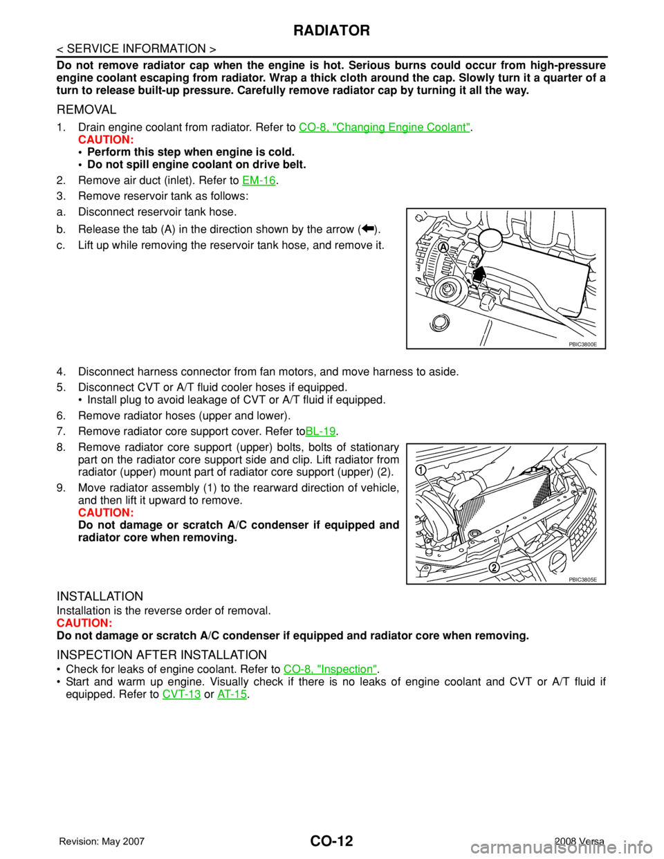
b. Release the tab (A) in the direction shown by the arrow ( ).
c. Lift up while removing the reservoir tank hose, and remove it.
4. Disconnect harness connector from fan motors, and move harness to aside.
5. Disconnect CVT or A/T fluid cooler hoses if equipped.
• Install plug to avoid leakage of CVT or A/T fluid if equipped.
6. Remove radiator hoses (upper and lower).
7. Remove radiator core support cover. Refer toBL-19
.
8. Remove radiator core support (upper) bolts, bolts of stationary
part on the radiator core support side and clip. Lift radiator from
radiator (upper) mount part of radiator core support (upper) (2).
9. Move radiator assembly (1) to the rearward direction of vehicle,
and then lift it upward to remove.
CAUTION:
Do not damage or scratch A/C condenser if equipped and
radiator core when removing.
INSTALLATION
Installation is the reverse order of removal.
CAUTION:
Do not damage or scratch A/C condenser if equipped and radiator core when removing.
INSPECTION AFTER INSTALLATION
• Check for leaks of engine coolant. Refer to CO-8, "Inspection".
• Start and warm up engine. Visually check if there is no leaks of engine coolant and CVT or A/T fluid if
equipped. Refer to CVT-13
or AT- 1 5.
PBIC3800E
PBIC3805E
Page 833 of 2771
CO-16
< SERVICE INFORMATION >
WATER PUMP
WATER PUMP
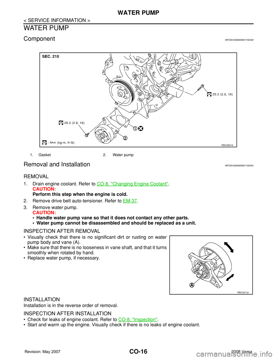
ComponentINFOID:0000000001702539
Removal and InstallationINFOID:0000000001702540
REMOVAL
1. Drain engine coolant. Refer to CO-8, "Changing Engine Coolant".
CAUTION:
Perform this step when the engine is cold.
2. Remove drive belt auto-tensioner. Refer to EM-37
.
3. Remove water pump.
CAUTION:
• Handle water pump vane so that it does not contact any other parts.
• Water pump cannot be disassembled and should be replaced as a unit.
INSPECTION AFTER REMOVAL
• Visually check that there is no significant dirt or rusting on water
pump body and vane (A).
• Make sure that there is no looseness in vane shaft, and that it turns
smoothly when rotated by hand.
• Replace water pump, if necessary.
INSTALLATION
Installation is in the reverse order of removal.
INSPECTION AFTER INSTALLATION
• Check for leaks of engine coolant. Refer to CO-8, "Inspection".
• Start and warm up the engine. Visually check if there is no leaks of engine coolant.
1. Gasket 2. Water pump
PBIC3921E
PBIC3313J
Page 834 of 2771
THERMOSTAT
CO-17
< SERVICE INFORMATION >
C
D
E
F
G
H
I
J
K
L
MA
CO
N
P O
THERMOSTAT
ComponentINFOID:0000000001702541
Removal and InstallationINFOID:0000000001702542
REMOVAL
1. Drain engine coolant. Refer to CO-8, "Changing Engine Coolant".
2. Remove water inlet.
3. Remove thermostat.
4. Remove water pump. Refer to CO-16
.
5. Remove thermostat housing.
INSPECTION AFTER REMOVAL
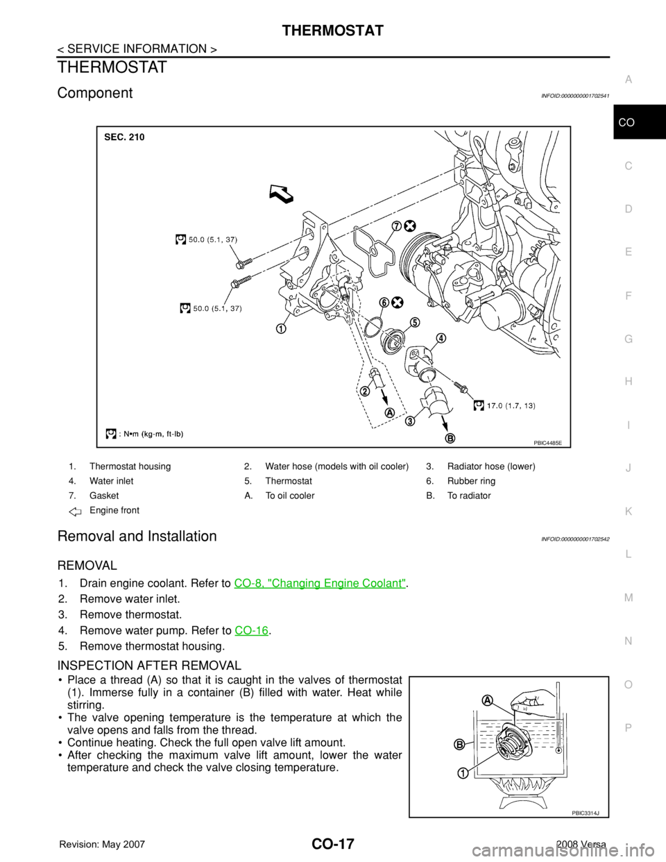
• Place a thread (A) so that it is caught in the valves of thermostat
(1). Immerse fully in a container (B) filled with water. Heat while
stirring.
• The valve opening temperature is the temperature at which the
valve opens and falls from the thread.
• Continue heating. Check the full open valve lift amount.
• After checking the maximum valve lift amount, lower the water
temperature and check the valve closing temperature.
1. Thermostat housing 2. Water hose (models with oil cooler) 3. Radiator hose (lower)
4. Water inlet 5. Thermostat 6. Rubber ring
7. Gasket A. To oil cooler B. To radiator
Engine front
PBIC4485E
PBIC3314J
Page 835 of 2771
CO-18
< SERVICE INFORMATION >
THERMOSTAT
• If out of the specification, replace thermostat.
INSTALLATION
Installation is in the reverse order of removal.
Thermostat
CAUTION:
Replace the rubber ring with a new one.
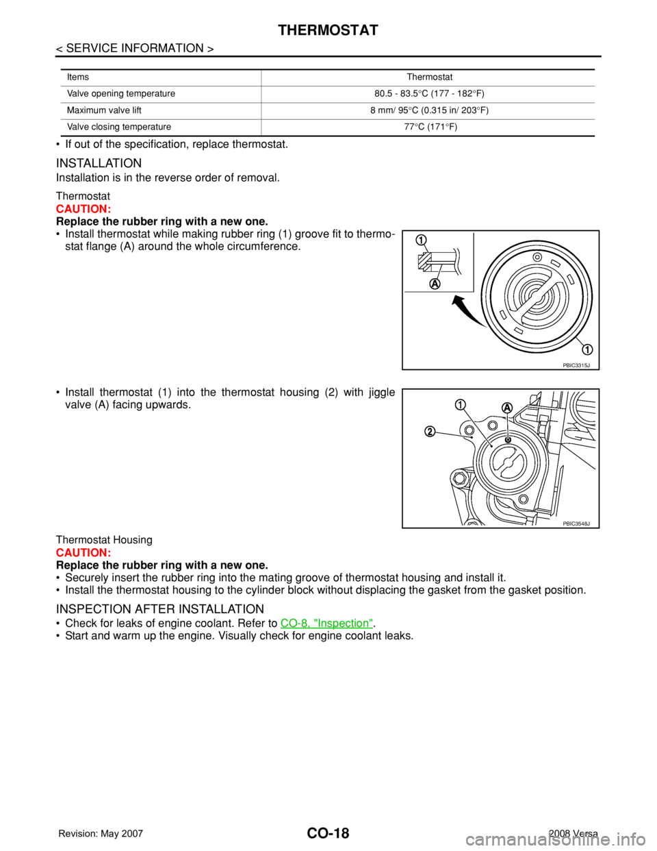
• Install thermostat while making rubber ring (1) groove fit to thermo-
stat flange (A) around the whole circumference.
• Install thermostat (1) into the thermostat housing (2) with jiggle
valve (A) facing upwards.
Thermostat Housing
CAUTION:
Replace the rubber ring with a new one.
• Securely insert the rubber ring into the mating groove of thermostat housing and install it.
• Install the thermostat housing to the cylinder block without displacing the gasket from the gasket position.
INSPECTION AFTER INSTALLATION
• Check for leaks of engine coolant. Refer to CO-8, "Inspection".
• Start and warm up the engine. Visually check for engine coolant leaks.
ItemsThermostat
Valve opening temperature 80.5 - 83.5°C (177 - 182°F)
Maximum valve lift 8 mm/ 95°C (0.315 in/ 203°F)
Valve closing temperature 77°C (171°F)
PBIC3315J
PBIC3548J
Page 838 of 2771
WATER OUTLET AND WATER CONTROL VALVE
CO-21
< SERVICE INFORMATION >
C
D
E
F
G
H
I
J
K
L
MA
CO
N
P O
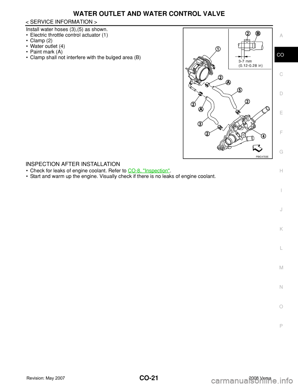
Install water hoses (3),(5) as shown.
• Electric throttle control actuator (1)
• Clamp (2)
• Water outlet (4)
• Paint mark (A)
• Clamp shall not interfere with the bulged area (B)
INSPECTION AFTER INSTALLATION
• Check for leaks of engine coolant. Refer to CO-8, "Inspection".
• Start and warm up the engine. Visually check if there is no leaks of engine coolant.
PBIC4703E
Page 840 of 2771
CVT-1
TRANSMISSION/TRANSAXLE
D
E
F
G
H
I
J
K
L
M
SECTION CVT
A
B
CVT
N
O
P
CONTENTS
CVT
SERVICE INFORMATION ............................5
INDEX FOR DTC .................................................5
Alphabetical Index .....................................................5
DTC No. Index ..........................................................5
PRECAUTIONS ...................................................7
Precaution for Supplemental Restraint System
(SRS) "AIR BAG" and "SEAT BELT PRE-TEN-
SIONER" ...................................................................
7
Precaution Necessary for Steering Wheel Rota-
tion After Battery Disconnect .....................................
7
Precaution for On Board Diagnosis (OBD) System
of CVT and Engine ....................................................
7
Service After Replacing TCM and Transaxle As-
sembly .......................................................................
8
Removal and Installation Procedure for CVT Unit
Connector ..................................................................
9
Precaution ...............................................................10
Service Notice or Precaution ...................................11
PREPARATION ..................................................12
Special Service Tool ...............................................12
Commercial Service Tool ........................................12
CVT FLUID .........................................................13
Checking CVT Fluid ................................................13
Changing CVT Fluid ................................................14
CVT Fluid Cooler Cleaning .....................................14
CVT SYSTEM .....................................................18
Cross-Sectional View - RE0F08A ...........................18
Control System ........................................................19
Hydraulic Control System ........................................20
TCM Function ..........................................................20
CAN Communication ...............................................21
Input/Output Signal of TCM .....................................22
Line Pressure and Secondary Pressure Control .....22
Shift Control ............................................................23
Lock-up and Select Control .....................................24
Control Valve ...........................................................25
ON BOARD DIAGNOSTIC (OBD) SYSTEM ....26
Introduction ..............................................................26
OBD-II Function for CVT System ............................26
One or Two Trip Detection Logic of OBD-II .............26
OBD-II Diagnostic Trouble Code (DTC) ..................26
Malfunction Indicator Lamp (MIL) ............................27
TROUBLE DIAGNOSIS ....................................29
DTC Inspection Priority Chart ..................................29
Fail-Safe ..................................................................29
How to Perform Trouble Diagnosis for Quick and
Accurate Repair .......................................................
30
CVT Electrical Parts Location ..................................35
Circuit Diagram ........................................................36
Inspections before Trouble Diagnosis .....................36
Road Test ................................................................40
Check before Engine Is Started ...............................41
Check at Idle ............................................................41
Cruise Test ..............................................................43
Vehicle Speed When Shifting Gears .......................45
TCM Terminal and Reference Value .......................45
CONSULT-III Function (TRANSMISSION) ..............47
Diagnosis Procedure without CONSULT-III ............55
DTC U1000 CAN COMMUNICATION LINE .....56
Description ...............................................................56
On Board Diagnosis Logic .......................................56
Possible Cause ........................................................56
DTC Confirmation Procedure ..................................56
Wiring Diagram - CVT - CAN ...................................57
Diagnosis Procedure ...............................................58
DTC U1010 TRANSMISSION CONTROL
MODULE (CAN) ................................................
59
Description ...............................................................59
On Board Diagnosis Logic .......................................59
Possible Cause ........................................................59
DTC Confirmation Procedure ..................................59
Diagnosis Procedure ...............................................59
DTC P0615 START SIGNAL CIRCUIT .............60
Page 843 of 2771

CVT-4
DTC P1740 LOCK-UP SELECT SOLENOID
VALVE CIRCUIT ..............................................
132
Description .............................................................132
CONSULT-III Reference Value in Data Monitor
Mode ......................................................................
132
On Board Diagnosis Logic .....................................132
Possible Cause ......................................................132
DTC Confirmation Procedure ................................132
Wiring Diagram - CVT - L/USSV ............................133
Diagnosis Procedure .............................................134
Component Inspection ...........................................135
DTC P1745 LINE PRESSURE CONTROL ......136
Description .............................................................136
On Board Diagnosis Logic .....................................136
Possible Cause ......................................................136
DTC Confirmation Procedure ................................136
Diagnosis Procedure .............................................136
DTC P1777 STEP MOTOR - CIRCUIT ............137
Description .............................................................137
CONSULT-III Reference Value in Data Monitor
Mode ......................................................................
137
On Board Diagnosis Logic .....................................137
Possible Cause ......................................................137
DTC Confirmation Procedure ................................137
Wiring Diagram - CVT - STM .................................138
Diagnosis Procedure .............................................139
Component Inspection ...........................................140
DTC P1778 STEP MOTOR - FUNCTION ........141
Description .............................................................141
CONSULT-III Reference Value in Data Monitor
Mode ......................................................................
141
On Board Diagnosis Logic .....................................141
Possible Cause ......................................................141
DTC Confirmation Procedure ................................141
Diagnosis Procedure .............................................142
OVERDRIVE CONTROL SWITCH ..................143
Description .............................................................143
CONSULT-III Reference Value in Data Monitor
Mode ......................................................................
143
Wiring Diagram - CVT - ODSW .............................144
Diagnosis Procedure .............................................144
Component Inspection ...........................................146
SHIFT POSITION INDICATOR CIRCUIT ........148
Description .............................................................148
CONSULT-III Reference Value in Data Monitor
Mode ......................................................................
148
Diagnosis Procedure .............................................148
TROUBLE DIAGNOSIS FOR SYMPTOMS .....149
Wiring Diagram - CVT - NONDTC .........................149
O/D OFF Indicator Lamp Does Not Come On ......151
Engine Cannot Be Started in "P" and "N" Position .153
In "P" Position, Vehicle Moves Forward or Back-
ward When Pushed ...............................................
153
In "N" Position, Vehicle Moves ..............................154
Large Shock "N" → "R" Position ...........................154
Vehicle Does Not Creep Backward in "R" Position .155
Vehicle Does Not Creep Forward in "D" or "L" Po-
sition ......................................................................
156
Vehicle Speed Does Not Change in "L" Position ..157
Vehicle Speed Does Not Change in overdrive-off
mode .....................................................................
158
Vehicle Speed Does Not Change in "D" Position .159
Vehicle Does Not Decelerate by Engine Brake ....159
TRANSMISSION CONTROL MODULE ...........161
Removal and Installation .......................................161
CVT SHIFT LOCK SYSTEM .............................162
Description ............................................................162
Shift Lock System Electrical Parts Location ..........162
Wiring Diagram - CVT - SHIFT .............................163
Diagnosis Procedure .............................................163
SHIFT CONTROL SYSTEM .............................167
Removal and Installation .......................................167
Control Device Disassembly and Assembly .........170
Selector Lever Knob Removal and Installation .....170
Adjustment of CVT Position ..................................171
Checking of CVT Position .....................................171
KEY INTERLOCK CABLE ...............................173
Removal and Installation .......................................173
AIR BREATHER HOSE ....................................176
Removal and Installation .......................................176
DIFFERENTIAL SIDE OIL SEAL .....................177
Removal and Installation .......................................177
TRANSAXLE ASSEMBLY ...............................178
Removal and Installation .......................................178
SERVICE DATA AND SPECIFICATIONS
(SDS) ................................................................
181
General Specification ............................................181
Vehicle Speed When Shifting Gears .....................181
Stall Speed ............................................................181
Line Pressure ........................................................181
Solenoid Valves ....................................................182
CVT Fluid Temperature Sensor ............................182
Primary Speed Sensor ..........................................182
Secondary Speed Sensor .....................................182
Removal and Installation .......................................182
Page 846 of 2771

PRECAUTIONS
CVT-7
< SERVICE INFORMATION >
D
E
F
G
H
I
J
K
L
MA
B
CVT
N
O
P
PRECAUTIONS
Precaution for Supplemental Restraint System (SRS) "AIR BAG" and "SEAT BELT
PRE-TENSIONER"
INFOID:0000000001703424
The Supplemental Restraint System such as “AIR BAG” and “SEAT BELT PRE-TENSIONER”, used along
with a front seat belt, helps to reduce the risk or severity of injury to the driver and front passenger for certain
types of collision. This system includes seat belt switch inputs and dual stage front air bag modules. The SRS
system uses the seat belt switches to determine the front air bag deployment, and may only deploy one front
air bag, depending on the severity of a collision and whether the front occupants are belted or unbelted.
Information necessary to service the system safely is included in the SRS and SB section of this Service Man-
ual.
WARNING:
• To avoid rendering the SRS inoperative, which could increase the risk of personal injury or death in
the event of a collision which would result in air bag inflation, all maintenance must be performed by
an authorized NISSAN/INFINITI dealer.
• Improper maintenance, including incorrect removal and installation of the SRS, can lead to personal
injury caused by unintentional activation of the system. For removal of Spiral Cable and Air Bag
Module, see the SRS section.
• Do not use electrical test equipment on any circuit related to the SRS unless instructed to in this
Service Manual. SRS wiring harnesses can be identified by yellow and/or orange harnesses or har-
ness connectors.
Precaution Necessary for Steering Wheel Rotation After Battery Disconnect
INFOID:0000000001703425
NOTE:
• This Procedure is applied only to models with Intelligent Key system and NVIS/IVIS (NISSAN/INFINITI
VEHICLE IMMOBILIZER SYSTEM - NATS).
• Remove and install all control units after disconnecting both battery cables with the ignition knob in the
″LOCK″ position.
• Always use CONSULT-III to perform self-diagnosis as a part of each function inspection after finishing work.
If DTC is detected, perform trouble diagnosis according to self-diagnostic results.
For models equipped with the Intelligent Key system and NVIS/IVIS, an electrically controlled steering lock
mechanism is adopted on the key cylinder.
For this reason, if the battery is disconnected or if the battery is discharged, the steering wheel will lock and
steering wheel rotation will become impossible.
If steering wheel rotation is required when battery power is interrupted, follow the procedure below before
starting the repair operation.
OPERATION PROCEDURE
1. Connect both battery cables.
NOTE:
Supply power using jumper cables if battery is discharged.
2. Use the Intelligent Key or mechanical key to turn the ignition switch to the ″ACC″ position. At this time, the
steering lock will be released.
3. Disconnect both battery cables. The steering lock will remain released and the steering wheel can be
rotated.
4. Perform the necessary repair operation.
5. When the repair work is completed, return the ignition switch to the ″LOCK″ position before connecting
the battery cables. (At this time, the steering lock mechanism will engage.)
6. Perform a self-diagnosis check of all control units using CONSULT-III.
Precaution for On Board Diagnosis (OBD) System of CVT and EngineINFOID:0000000001703426
The ECM has an on board diagnostic system. It will light up the malfunction indicator lamp (MIL) to warn the
driver of a malfunction causing emission deterioration.
CAUTION: