2008 NISSAN TEANA stop start
[x] Cancel search: stop startPage 1206 of 5121

DEF-56
< ECU DIAGNOSIS >
BCM (BODY CONTROL MODULE)
DTC Index
INFOID:0000000003940044
NOTE:
The details of time display are as follows.
CRNT: A malfunction is detected now.
PAST: A malfunction was detected in the past.
IGN counter is displayed on Freeze Frame Data. For details of Freeze Frame Data and IGN Counter, refer to
DEF-8, "
COMMON ITEM : CONSULT-III Function (BCM - COMMON ITEM)".
4 B2013: ID DISCORD BCM-S/L
B2014: CHAIN OF S/L-BCM
B2553: IGNITION RELAY
B2555: STOP LAMP
B2556: PUSH-BTN IGN SW
B2557: VEHICLE SPEED
B2560: STARTER CONT RELAY
B2601: SHIFT POSITION
B2602: SHIFT POSITION
B2603: SHIFT POSI STATUS
B2604: PNP SW
B2605: PNP SW
B2606: S/L RELAY
B2607: S/L RELAY
B2608: STARTER RELAY
B2609: S/L STATUS
B260A: IGNITION RELAY
B260B: STEERING LOCK UNIT
B260C: STEERING LOCK UNIT
B260D: STEERING LOCK UNIT
B260F: ENG STATE SIG LOST
B2612: S/L STATUS
B2614: ACC RELAY CIRC
B2615: BLOWER RELAY CIRC
B2616: IGN RELAY CIRC
B2617: STARTER RELAY CIRC
B2618: BCM
B2619: BCM
B261A: PUSH-BTN IGN SW
B261E: VEHICLE TYPE
B26E1: ENG STATE NO RES
B26E9: S/L STATUS
B26EA: KEY REGISTRATION
U0415: VEHICLE SPEED SIG
5 B2621: INSIDE ANTENNA
B2622: INSIDE ANTENNA
B2623: INSIDE ANTENNA Priority DTC
CONSULT display Fail-safe Freeze Frame DataIntelligent Key warn-
ing lamp ONReference page
No DTC is detected.
further testing
may be required.————
U1000: CAN COMM CIRCUIT — — —BCS-33
U1010: CONTROL UNIT (CAN) — — —BCS-34
U0415: VEHICLE SPEED SIG — — —BCS-35
B2013: ID DISCORD BCM-S/L××—SEC-46
B2014: CHAIN OF S/L-BCM××—SEC-47
B2190: NATS ANTENNA AMP×——SEC-39
B2191: DIFFERENCE OF KEY×——SEC-42
Page 1207 of 5121
BCM (BODY CONTROL MODULE)
DEF-57
< ECU DIAGNOSIS >
C
D
E
F
G
H
I
J
K
MA
B
DEF
N
O
P
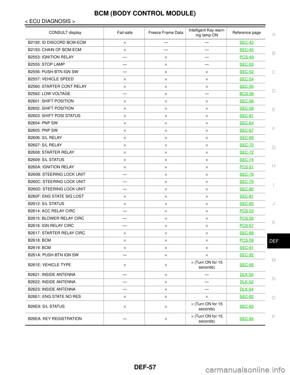
B2192: ID DISCORD BCM-ECM×——SEC-43
B2193: CHAIN OF BCM-ECM×——SEC-45
B2553: IGNITION RELAY —×—PCS-49
B2555: STOP LAMP —×—SEC-50
B2556: PUSH-BTN IGN SW —××SEC-52
B2557: VEHICLE SPEED×××SEC-54
B2560: STARTER CONT RELAY×××SEC-55
B2562: LOW VOLTAGE —×—BCS-36
B2601: SHIFT POSITION×××SEC-56
B2602: SHIFT POSITION×××SEC-59
B2603: SHIFT POSI STATUS×××SEC-61
B2604: PNP SW×××SEC-64
B2605: PNP SW×××SEC-67
B2606: S/L RELAY×××SEC-69
B2607: S/L RELAY×××SEC-70
B2608: STARTER RELAY×××SEC-72
B2609: S/L STATUS×××SEC-74
B260A: IGNITION RELAY×××PCS-51
B260B: STEERING LOCK UNIT —××SEC-78
B260C: STEERING LOCK UNIT —××SEC-79
B260D: STEERING LOCK UNIT —××SEC-80
B260F: ENG STATE SIG LOST×××SEC-81
B2612: S/L STATUS×××SEC-85
B2614: ACC RELAY CIRC —××PCS-53
B2615: BLOWER RELAY CIRC —××PCS-55
B2616: IGN RELAY CIRC —××PCS-57
B2617: STARTER RELAY CIRC×××SEC-89
B2618: BCM×××PCS-59
B2619: BCM×××SEC-91
B261A: PUSH-BTN IGN SW —××SEC-92
B261E: VEHICLE TYPE××× (Turn ON for 15
seconds)SEC-95
B2621: INSIDE ANTENNA —×—DLK-50
B2622: INSIDE ANTENNA —×—DLK-52
B2623: INSIDE ANTENNA —×—DLK-54
B26E1: ENG STATE NO RES×××SEC-82
B26E9: S/L STATUS××× (Turn ON for 15
seconds)SEC-83
B26EA: KEY REGISTRATION —×× (Turn ON for 15
seconds)SEC-84
CONSULT display Fail-safe Freeze Frame DataIntelligent Key warn-
ing lamp ONReference page
Page 1248 of 5121
![NISSAN TEANA 2008 Service Manual DLK-32
< FUNCTION DIAGNOSIS >[WITH INTELLIGENT KEY SYSTEM]
INTELLIGENT KEY SYSTEM
WARNING METHOD
The following table shows the alarm or warning methods with chime.
Information display (combination met](/manual-img/5/57391/w960_57391-1247.png "NISSAN TEANA 2008 Service Manual DLK-32
< FUNCTION DIAGNOSIS >[WITH INTELLIGENT KEY SYSTEM]
INTELLIGENT KEY SYSTEM
WARNING METHOD
The following table shows the alarm or warning methods with chime.
Information display (combination met")
DLK-32
< FUNCTION DIAGNOSIS >[WITH INTELLIGENT KEY SYSTEM]
INTELLIGENT KEY SYSTEM
WARNING METHOD
The following table shows the alarm or warning methods with chime.
Information display (combination meter), “KEY” indicator or key slot illumination when the warning conditions
are met.
OFF position warning For internal Ignition switch: ACC position.
Door switch (driver side): ON (Door is open).
For externalOFF position warning (for internal) is in active mode, driver side door is closed.
NOTE:
OFF position (for external) active only when each of the sequence has oc-
curred as per the following: P position warning → ACC warning → OFF posi-
tion warning (for internal) → OFF position warning (for internal)
P position warning Shift position: Any position except the P position.
Engine is running to stopped (ignition switch is ON to OFF).
ACC warning When P position warning is in active mode, shift position changes from the
P position.
Ignition switch: ACC position.
Ta k e a w a y w a r n i n gDoor is open to close Ignition switch: Any position except the LOCK position.
Door switch: ON to OFF (door is open to close).
Intelligent Key can not be detected inside the vehicle.
Door is open Door switch: ON (door is open).
Key ID verification every 5 seconds when registered Intelligent Key can not
be detected inside the vehicle.
Push button-ignition
switch operation Ignition switch: Any position except the LOCK position.
Press push-button ignition switch.
Intelligent Key can not be detected inside the vehicle.
Intelligent Key is removed
from key slotWhen Intelligent Key is removed from key slot, Intelligent Key can not be de-
tected inside the vehicle.
Door lock operation warn-
ingRequest switch operationWhen request switch is pushed (lock operation) under the following conditions.
All doors are closed.
All doors are unlocked.
Intelligent Key is inside vehicle.
Intelligent Key button op-
erationWhen Intelligent Key button is pushed (lock operation) under the following con-
ditions.
Door switch: ON (any door is open).
For 3 seconds after Intelligent Key is removed from key slot.
Key warning Ignition switch is in the OFF position.
Driver side door switch: ON (driver side door is open).
Intelligent Key is inserted in key slot.
Intelligent Key insert information Door switch: ON to OFF (door is open to close).
Ignition switch: OFF to ON position.
Intelligent Key is out of key slot.
Intelligent Key can not be detected inside the vehicle.
Engine start informationIgnition switch is in the
ON position Ignition switch: ON position.
Shift position: P position.
Engine is stopped.
Ignition switch is in any
position except the ON
position Ignition switch: Any position except the ON position.
Shift position: P position.
Intelligent Key is inserted in key slot or Intelligent Key can be detected inside
the vehicle.
Steering lock information When steering lock can not be released after ignition switch is turned ON.
Intelligent Key low battery warningWhen Intelligent Key is battery low, BCM is detected after ignition switch is
turned ON.
Key ID warningWhen registered Intelligent Key can not be detected inside the vehicle after ig-
nition switch is turned ON. Warning/Information functions Operation procedure
Page 1261 of 5121
![NISSAN TEANA 2008 Service Manual DIAGNOSIS SYSTEM (BCM)
DLK-45
< FUNCTION DIAGNOSIS >[WITH INTELLIGENT KEY SYSTEM]
C
D
E
F
G
H
I
J
L
MA
B
DLK
N
O
P
ACTIVE TEST
CLUCH SWNOTE:
This item is displayed, but cannot be monitored.
BRAKE SW](/manual-img/5/57391/w960_57391-1260.png "NISSAN TEANA 2008 Service Manual DIAGNOSIS SYSTEM (BCM)
DLK-45
< FUNCTION DIAGNOSIS >[WITH INTELLIGENT KEY SYSTEM]
C
D
E
F
G
H
I
J
L
MA
B
DLK
N
O
P
ACTIVE TEST
CLUCH SWNOTE:
This item is displayed, but cannot be monitored.
BRAKE SW")
DIAGNOSIS SYSTEM (BCM)
DLK-45
< FUNCTION DIAGNOSIS >[WITH INTELLIGENT KEY SYSTEM]
C
D
E
F
G
H
I
J
L
MA
B
DLK
N
O
P
ACTIVE TEST
CLUCH SWNOTE:
This item is displayed, but cannot be monitored.
BRAKE SW 1 Indicates [ON/OFF] condition of brake switch.
DETE/CANCL SW Indicates [ON/OFF] condition of the P position.
SFT PN/N SW Indicates [ON/OFF] condition of the P or N position.
S/L -LOCK Indicates [ON/OFF] condition of steering lock unit (LOCK).
S/L -UNLOCK Indicates [ON/OFF] condition of steering lock unit (UNLOCK).
S/L RELAY -F/B Indicates [ON/OFF] condition of steering lock relay.
UNLK SEN -DR Indicates [ON/OFF] condition of driver door UNLOCK status.
PUSH SW -IPDM Indicates [ON/OFF] condition of push-button ignition switch.
IGN RLY1 -F/B Indicates [ON/OFF] condition of ignition relay 1.
DETE SW -IPDM Indicates [ON/OFF] condition of the P position.
SFT PN -IPDM Indicates [ON/OFF] condition of the P or N position.
SFT P -MET Indicates [ON/OFF] condition of the P position.
SFT N -MET Indicates [ON/OFF] condition of the N position.
ENGINE STATE Indicates [STOP/STALL/CRANK/RUN] condition of engine states.
S/L LOCK-IPDM Indicates [ON/OFF] condition of steering lock unit (LOCK).
S/L UNLK-IPDM Indicates [ON/OFF] condition of steering lock unit (UNLOCK).
S/L RELAY-REQ Indicates [ON/OFF] condition of steering lock relay.
VEH SPEED 1 Displays the vehicle speed signal received from combination meter by numerical value [Km/h].
VEH SPEED 2 Displays the vehicle speed signal received from ABS, VDC or CVT by numerical value [Km/h].
DOOR STAT-DR Indicates [LOCK/READY/UNLK] condition of driver side door status.
DOOR STAT-AS Indicates [LOCK/READY/UNLK] condition of passenger side door status.
ID OK FLAG Indicates [SET/RESET] condition of key ID.
PRMT ENG STRT Indicates [SET/RESET] condition of engine start possibility.
PRMT RKE STRTNOTE:
This item is displayed, but cannot be monitored.
KEY SW -SLOT Indicates [ON/OFF] condition of key slot.
TRNK/HAT MNTR Indicates [ON/OFF] condition of trunk lid.
RKE-LOCK Indicates [ON/OFF] condition of LOCK signal from Intelligent Key.
RKE-UNLOCK Indicates [ON/OFF] condition of UNLOCK signal from Intelligent Key.
RKE-TR/BD Indicates [ON/OFF] condition of TRUNK OPEN signal from Intelligent Key.
RKE-PANICNOTE:
This item is displayed, but cannot be monitored.
RKE-P/W OPENNOTE:
This item is displayed, but cannot be monitored.
RKE-MODE CHG Indicates [ON/OFF] condition of MODE CHANGE signal from Intelligent Key.
RKE OPE COUN1When remote keyless entry receiver receives the signal transmitted while operating on Intelligent Key, the
numerical values start changing.
RKE OPE COUN2NOTE:
This item is displayed, but cannot be monitored. Monitor Item Condition
Page 1369 of 5121
![NISSAN TEANA 2008 Service Manual BCM (BODY CONTROL MODULE)
DLK-153
< ECU DIAGNOSIS >[WITH INTELLIGENT KEY SYSTEM]
C
D
E
F
G
H
I
J
L
MA
B
DLK
N
O
P
DTC IndexINFOID:0000000003904116
NOTE:
The details of time display are as follows.
C](/manual-img/5/57391/w960_57391-1368.png "NISSAN TEANA 2008 Service Manual BCM (BODY CONTROL MODULE)
DLK-153
< ECU DIAGNOSIS >[WITH INTELLIGENT KEY SYSTEM]
C
D
E
F
G
H
I
J
L
MA
B
DLK
N
O
P
DTC IndexINFOID:0000000003904116
NOTE:
The details of time display are as follows.
C")
BCM (BODY CONTROL MODULE)
DLK-153
< ECU DIAGNOSIS >[WITH INTELLIGENT KEY SYSTEM]
C
D
E
F
G
H
I
J
L
MA
B
DLK
N
O
P
DTC IndexINFOID:0000000003904116
NOTE:
The details of time display are as follows.
CRNT: A malfunction is detected now.
PAST: A malfunction was detected in the past.
IGN counter is displayed on Freeze Frame Data. For details of Freeze Frame Data and IGN Counter, refer to
BCS-16, "
COMMON ITEM : CONSULT-III Function (BCM - COMMON ITEM)".
4 B2013: ID DISCORD BCM-S/L
B2014: CHAIN OF S/L-BCM
B2553: IGNITION RELAY
B2555: STOP LAMP
B2556: PUSH-BTN IGN SW
B2557: VEHICLE SPEED
B2560: STARTER CONT RELAY
B2601: SHIFT POSITION
B2602: SHIFT POSITION
B2603: SHIFT POSI STATUS
B2604: PNP SW
B2605: PNP SW
B2606: S/L RELAY
B2607: S/L RELAY
B2608: STARTER RELAY
B2609: S/L STATUS
B260A: IGNITION RELAY
B260B: STEERING LOCK UNIT
B260C: STEERING LOCK UNIT
B260D: STEERING LOCK UNIT
B260F: ENG STATE SIG LOST
B2612: S/L STATUS
B2614: ACC RELAY CIRC
B2615: BLOWER RELAY CIRC
B2616: IGN RELAY CIRC
B2617: STARTER RELAY CIRC
B2618: BCM
B2619: BCM
B261A: PUSH-BTN IGN SW
B261E: VEHICLE TYPE
B26E1: ENG STATE NO RES
B26E9: S/L STATUS
B26EA: KEY REGISTRATION
U0415: VEHICLE SPEED SIG
5 B2621: INSIDE ANTENNA
B2622: INSIDE ANTENNA
B2623: INSIDE ANTENNA Priority DTC
CONSULT display Fail-safe Freeze Frame DataIntelligent Key warn-
ing lamp ONReference page
No DTC is detected.
further testing
may be required.————
U1000: CAN COMM CIRCUIT — — —BCS-33
U1010: CONTROL UNIT (CAN) — — —BCS-34
U0415: VEHICLE SPEED SIG — — —BCS-35
B2013: ID DISCORD BCM-S/L××—SEC-46
B2014: CHAIN OF S/L-BCM××—SEC-47
B2190: NATS ANTENNA AMP×——SEC-39
B2191: DIFFERENCE OF KEY×——SEC-42
Page 1370 of 5121
![NISSAN TEANA 2008 Service Manual DLK-154
< ECU DIAGNOSIS >[WITH INTELLIGENT KEY SYSTEM]
BCM (BODY CONTROL MODULE)
B2192: ID DISCORD BCM-ECM×——SEC-43
B2193: CHAIN OF BCM-ECM×——SEC-45
B2553: IGNITION RELAY —×—PCS-49
B255](/manual-img/5/57391/w960_57391-1369.png "NISSAN TEANA 2008 Service Manual DLK-154
< ECU DIAGNOSIS >[WITH INTELLIGENT KEY SYSTEM]
BCM (BODY CONTROL MODULE)
B2192: ID DISCORD BCM-ECM×——SEC-43
B2193: CHAIN OF BCM-ECM×——SEC-45
B2553: IGNITION RELAY —×—PCS-49
B255")
DLK-154
< ECU DIAGNOSIS >[WITH INTELLIGENT KEY SYSTEM]
BCM (BODY CONTROL MODULE)
B2192: ID DISCORD BCM-ECM×——SEC-43
B2193: CHAIN OF BCM-ECM×——SEC-45
B2553: IGNITION RELAY —×—PCS-49
B2555: STOP LAMP —×—SEC-50
B2556: PUSH-BTN IGN SW —××SEC-52
B2557: VEHICLE SPEED×××SEC-54
B2560: STARTER CONT RELAY×××SEC-55
B2562: LOW VOLTAGE —×—BCS-36
B2601: SHIFT POSITION×××SEC-56
B2602: SHIFT POSITION×××SEC-59
B2603: SHIFT POSI STATUS×××SEC-61
B2604: PNP SW×××SEC-64
B2605: PNP SW×××SEC-67
B2606: S/L RELAY×××SEC-69
B2607: S/L RELAY×××SEC-70
B2608: STARTER RELAY×××SEC-72
B2609: S/L STATUS×××SEC-74
B260A: IGNITION RELAY×××PCS-51
B260B: STEERING LOCK UNIT —××SEC-78
B260C: STEERING LOCK UNIT —××SEC-79
B260D: STEERING LOCK UNIT —××SEC-80
B260F: ENG STATE SIG LOST×××SEC-81
B2612: S/L STATUS×××SEC-85
B2614: ACC RELAY CIRC —××PCS-53
B2615: BLOWER RELAY CIRC —××PCS-55
B2616: IGN RELAY CIRC —××PCS-57
B2617: STARTER RELAY CIRC×××SEC-89
B2618: BCM×××PCS-59
B2619: BCM×××SEC-91
B261A: PUSH-BTN IGN SW —××SEC-92
B261E: VEHICLE TYPE××× (Turn ON for 15
seconds)SEC-95
B2621: INSIDE ANTENNA —×—DLK-50
B2622: INSIDE ANTENNA —×—DLK-52
B2623: INSIDE ANTENNA —×—DLK-54
B26E1: ENG STATE NO RES×××SEC-82
B26E9: S/L STATUS××× (Turn ON for 15
seconds)SEC-83
B26EA: KEY REGISTRATION —×× (Turn ON for 15
seconds)SEC-84
CONSULT display Fail-safe Freeze Frame DataIntelligent Key warn-
ing lamp ONReference page
Page 1400 of 5121
![NISSAN TEANA 2008 Service Manual DLK-184
< SYMPTOM DIAGNOSIS >[WITH INTELLIGENT KEY SYSTEM]
SQUEAK AND RATTLE TROUBLE DIAGNOSES
Inspection Procedure
INFOID:0000000003941378
Refer to Table of Contents for specific component removal an](/manual-img/5/57391/w960_57391-1399.png "NISSAN TEANA 2008 Service Manual DLK-184
< SYMPTOM DIAGNOSIS >[WITH INTELLIGENT KEY SYSTEM]
SQUEAK AND RATTLE TROUBLE DIAGNOSES
Inspection Procedure
INFOID:0000000003941378
Refer to Table of Contents for specific component removal an")
DLK-184
< SYMPTOM DIAGNOSIS >[WITH INTELLIGENT KEY SYSTEM]
SQUEAK AND RATTLE TROUBLE DIAGNOSES
Inspection Procedure
INFOID:0000000003941378
Refer to Table of Contents for specific component removal and installation information.
INSTRUMENT PANEL
Most incidents are caused by contact and movement between:
1. Cluster lid A and instrument panel
2. Acrylic lens and combination meter housing
3. Instrument panel to front pillar garnish
4. Instrument panel to windshield
5. Instrument panel mounting pins
6. Wiring harnesses behind the combination meter
7. A/C defroster duct and duct joint
These incidents can usually be located by tapping or moving the components to duplicate the noise or by
pressing on the components while driving to stop the noise. Most of these incidents can be repaired by apply-
ing felt cloth tape or silicon spray (in hard to reach areas). Urethane pads can be used to insulate wiring har-
ness.
CAUTION:
Never use silicone spray to isolate a squeak or rattle. If the area is saturated with silicone, the recheck
of repair becomes impossible.
CENTER CONSOLE
Components to pay attention to include:
1. Shifter assembly cover to finisher
2. A/C control unit and cluster lid C
3. Wiring harnesses behind audio and A/C control unit
The instrument panel repair and isolation procedures also apply to the center console.
DOORS
Pay attention to the following:
1. Finisher and inner panel making a slapping noise
2. Inside handle escutcheon to door finisher
3. Wiring harnesses tapping
4. Door striker out of alignment causing a popping noise on starts and stops
Tapping or moving the components or pressing on them while driving to duplicate the conditions can isolate
many of these incidents. The areas can usually be insulated with felt cloth tape or insulator foam blocks to
repair the noise.
TRUNK
Trunk noises are often caused by a loose jack or loose items put into the trunk by the customer.
In addition look for the following:
1. Trunk lid dumpers out of adjustment
2. Trunk lid striker out of adjustment
3. Trunk lid torsion bars knocking together
4. A loose license plate or bracket
Most of these incidents can be repaired by adjusting, securing or insulating the item(s) or component(s) caus-
ing the noise.
SUNROOF/HEADLINING
Noises in the sunroof/headlining area can often be traced to one of the following:
1. Sunroof lid, rail, linkage or seals making a rattle or light knocking noise
2. Sunvisor shaft shaking in the holder
3. Front or rear windshield touching headlining and squeaking
Again, pressing on the components to stop the noise while duplicating the conditions can isolate most of these
incidents. Repairs usually consist of insulating with felt cloth tape.
Page 1473 of 5121
![NISSAN TEANA 2008 Service Manual EC-12
< BASIC INSPECTION >[VQ25DE, VQ35DE]
INSPECTION AND ADJUSTMENT
2. Rev engine between 2,000 and 3,000 rpm 2 or 3 times under no
load, then run engine at idle speed for about 1 minute.
3. Check id](/manual-img/5/57391/w960_57391-1472.png "NISSAN TEANA 2008 Service Manual EC-12
< BASIC INSPECTION >[VQ25DE, VQ35DE]
INSPECTION AND ADJUSTMENT
2. Rev engine between 2,000 and 3,000 rpm 2 or 3 times under no
load, then run engine at idle speed for about 1 minute.
3. Check id")
EC-12
< BASIC INSPECTION >[VQ25DE, VQ35DE]
INSPECTION AND ADJUSTMENT
2. Rev engine between 2,000 and 3,000 rpm 2 or 3 times under no
load, then run engine at idle speed for about 1 minute.
3. Check idle speed.
For procedure, refer to EC-14, "
IDLE SPEED : Special Repair
Requirement".
For specification, refer to EC-414, "
Idle Speed".
Is the inspection result normal?
YES >> GO TO 10.
NO >> GO TO 4.
4.PERFORM ACCELERATOR PEDAL RELEASED POSITION LEARNING
1. Stop engine.
2. Perform EC-15, "
ACCELERATOR PEDAL RELEASED POSITION LEARNING : Special Repair Require-
ment".
>> GO TO 5.
5.PERFORM THROTTLE VALVE CLOSED POSITION LEARNING
Perform EC-16, "
THROTTLE VALVE CLOSED POSITION LEARNING : Special Repair Requirement".
>> GO TO 6.
6.PERFORM IDLE AIR VOLUME LEARNING
Perform EC-16, "
IDLE AIR VOLUME LEARNING : Special Repair Requirement".
Is Idle Air Volume Learning carried out successfully?
YES >> GO TO 7.
NO >> Follow the instruction of Idle Air Volume Learning. Then GO TO 4.
7.CHECK TARGET IDLE SPEED AGAIN
1. Start engine and warm it up to normal operating temperature.
2. Check idle speed.
For procedure, refer to EC-14, "
IDLE SPEED : Special Repair Requirement".
For specification, refer to EC-414, "
Idle Speed".
Is the inspection result normal?
YES >> GO TO 10.
NO >> GO TO 8.
8.DETECT MALFUNCTIONING PART
Check the Following.
Check camshaft position sensor (PHASE) and circuit. Refer to EC-223, "
Diagnosis Procedure".
Check crankshaft position sensor (POS) and circuit. Refer to EC-219, "
Diagnosis Procedure".
Is the inspection result normal?
YES >> GO TO 9.
NO >> 1. Repair or replace malfunctioning part.
2. GO TO 4.
9.CHECK ECM FUNCTION
1. Substitute with a non-malfunctioning ECM to check ECM function. (ECM may be the cause of the incident,
although this is rare.)
2. Perform initialization of NVIS (NATS) system and registration of all NVIS (NATS) ignition key IDs. Refer to
SEC-8, "
ECM RE-COMMUNICATING FUNCTION : Description".
>> GO TO 4.
10.CHECK IGNITION TIMING
1. Run engine at idle.
PBIA8513J