2008 NISSAN TEANA heater
[x] Cancel search: heaterPage 1790 of 5121
![NISSAN TEANA 2008 Service Manual ELECTRICAL LOAD SIGNAL
EC-329
< COMPONENT DIAGNOSIS >[VQ25DE, VQ35DE]
C
D
E
F
G
H
I
J
K
L
MA
EC
N
P O
ELECTRICAL LOAD SIGNAL
DescriptionINFOID:0000000003856832
The electrical load signal (Headlamp swi](/manual-img/5/57391/w960_57391-1789.png "NISSAN TEANA 2008 Service Manual ELECTRICAL LOAD SIGNAL
EC-329
< COMPONENT DIAGNOSIS >[VQ25DE, VQ35DE]
C
D
E
F
G
H
I
J
K
L
MA
EC
N
P O
ELECTRICAL LOAD SIGNAL
DescriptionINFOID:0000000003856832
The electrical load signal (Headlamp swi")
ELECTRICAL LOAD SIGNAL
EC-329
< COMPONENT DIAGNOSIS >[VQ25DE, VQ35DE]
C
D
E
F
G
H
I
J
K
L
MA
EC
N
P O
ELECTRICAL LOAD SIGNAL
DescriptionINFOID:0000000003856832
The electrical load signal (Headlamp switch signal, rear window defogger switch signal, etc.) is transferred
through the CAN communication line from BCM to ECM via IPDM E/R.
Component Function CheckINFOID:0000000003856833
1.CHECK REAR WINDOW DEFOGGER SWITCH FUNCTION
1. Turn ignition switch ON.
2. Connect CONSULT-III and select “DATA MONITOR” mode.
3. Select “LOAD SIGNAL” and check indication under the following conditions.
Is the inspection result normal?
YES >> GO TO 2.
NO >> Go to EC-329, "
Diagnosis Procedure".
2.CHECK LIGHTING SWITCH FUNCTION
Check “LOAD SIGNAL” indication under the following conditions.
Is the inspection result normal?
YES >> GO TO 3.
NO >> Go to EC-329, "
Diagnosis Procedure".
3.CHECK HEATER FAN CONTROL SWITCH FUNCTION
Select “HEATER FAN SW” and check indication under the following conditions.
Is the inspection result normal?
YES >> INSPECTION END
NO >> Go to EC-329, "
Diagnosis Procedure".
Diagnosis ProcedureINFOID:0000000003856834
1.INSPECTION START
Confirm the malfunctioning circuit (rear window defogger, headlamp or heater fan). Refer to EC-329, "
Compo-
nent Function Check".
Which circuit is related to the incident?
Rear window defogger>>GO TO 2.
Headlamp>>GO TO 3.
Heater fan>>GO TO 4.
2.CHECK REAR WINDOW DEFOGGER SYSTEM
Refer to DEF-3, "
Work Flow".
Monitor item Condition Indication
LOAD SIGNAL Rear window defogger switchON ON
OFF OFF
Monitor item Condition Indication
LOAD SIGNAL Lighting switchON at 2nd position ON
OFF OFF
Monitor item Condition Indication
HEATER FAN SW Heater fan control switchON ON
OFF OFF
Page 1791 of 5121
![NISSAN TEANA 2008 Service Manual EC-330
< COMPONENT DIAGNOSIS >[VQ25DE, VQ35DE]
ELECTRICAL LOAD SIGNAL
>> INSPECTION END
3.CHECK HEADLAMP SYSTEM
Refer to EXL-7, "
Work Flow" (XENON TYPE) or EXL-198, "Work Flow" (HALOGEN TYPE).
>> INS](/manual-img/5/57391/w960_57391-1790.png "NISSAN TEANA 2008 Service Manual EC-330
< COMPONENT DIAGNOSIS >[VQ25DE, VQ35DE]
ELECTRICAL LOAD SIGNAL
>> INSPECTION END
3.CHECK HEADLAMP SYSTEM
Refer to EXL-7, \"
Work Flow\" (XENON TYPE) or EXL-198, \"Work Flow\" (HALOGEN TYPE).
>> INS")
EC-330
< COMPONENT DIAGNOSIS >[VQ25DE, VQ35DE]
ELECTRICAL LOAD SIGNAL
>> INSPECTION END
3.CHECK HEADLAMP SYSTEM
Refer to EXL-7, "
Work Flow" (XENON TYPE) or EXL-198, "Work Flow" (HALOGEN TYPE).
>> INSPECTION END
4.CHECK HEATER FAN CONTROL SYSTEM
Refer to VTL-5, "
System Description".
>> INSPECTION END
Page 1819 of 5121
![NISSAN TEANA 2008 Service Manual EC-358
< ECU DIAGNOSIS >[VQ25DE, VQ35DE]
ECM
TP SEN 1-B1 Ignition switch: ON
(Engine stopped)
Selector lever: DAccelerator pedal: Fully released More than 0.36 V
Accelerator pedal: Fully depressed](/manual-img/5/57391/w960_57391-1818.png "NISSAN TEANA 2008 Service Manual EC-358
< ECU DIAGNOSIS >[VQ25DE, VQ35DE]
ECM
TP SEN 1-B1 Ignition switch: ON
(Engine stopped)
Selector lever: DAccelerator pedal: Fully released More than 0.36 V
Accelerator pedal: Fully depressed")
EC-358
< ECU DIAGNOSIS >[VQ25DE, VQ35DE]
ECM
TP SEN 1-B1 Ignition switch: ON
(Engine stopped)
Selector lever: DAccelerator pedal: Fully released More than 0.36 V
Accelerator pedal: Fully depressed Less than 4.75 V
TP SEN 2-B1*
1 Ignition switch: ON
(Engine stopped)
Selector lever: DAccelerator pedal: Fully released More than 0.36 V
Accelerator pedal: Fully depressed Less than 4.75 V
INT/A TEMP SE Ignition switch: ONIndicates intake air tempera-
ture
START SIGNAL Ignition switch: ON → START → ON OFF → ON → OFF
CLSD THL POS Ignition switch: ON
(Engine stopped)Accelerator pedal: Fully released ON
Accelerator pedal: Slightly depressed OFF
AIR COND SIG Engine: After warming up, idle the
engineAir conditioner switch: OFF OFF
Air conditioner switch: ON
(Compressor operates.)ON
P/N POSI SW Ignition switch: ONSelector lever: P or N ON
Selector lever: Except above OFF
PW/ST SIGNAL Engine: After warming up, idle the
engineSteering wheel: Not being turned OFF
Steering wheel: Being turned ON
LOAD SIGNAL Ignition switch: ONRear window defogger switch: ON
and/or
Lighting switch: 2nd positionON
Rear window defogger switch and lighting
switch: OFFOFF
IGNITION SW Ignition switch: ON → OFF → ON ON → OFF → ON
HEATER FAN SW Engine: After warming up, idle the
engineHeater fan switch: ON ON
Heater fan switch: OFF OFF
BRAKE SW Ignition switch: ONBrake pedal: Fully released OFF
Brake pedal: Slightly depressed ON
INJ PULSE-B1 Engine: After warming up
Selector lever: P or N
Air conditioner switch: OFF
No loadIdle 2.0 - 3.0 msec
2,000 rpm 1.9 - 2.9 msec
INJ PULSE-B2 Engine: After warming up
Selector lever: P or N
Air conditioner switch: OFF
No loadIdle 2.0 - 3.0 msec
2,000 rpm 1.9 - 2.9 msec
IGN TIMING Engine: After warming up
Selector lever: P or N
Air conditioner switch: OFF
No loadIdle 7° - 17° BTDC
2,000 rpm 25° - 45° BTDC
CAL/LD VALUE Engine: After warming up
Selector lever: P or N
Air conditioner switch: OFF
No loadIdle 5% - 35%
2,500 rpm 5% - 35%
MASS AIRFLOW Engine: After warming up
Selector lever: P or N
Air conditioner switch: OFF
No loadIdle 2.0 - 6.0 g·m/s
2,500 rpm 7.0 - 20.0 g·m/s
PURG VOL C/V Engine: After warming up
Selector lever: P or N
Air conditioner switch: OFF
No loadIdle
(Accelerator pedal: Not depressed even
slightly, after engine starting.)0%
2,000 rpm — Monitor Item Condition Values/Status
Page 1822 of 5121
![NISSAN TEANA 2008 Service Manual ECM
EC-361
< ECU DIAGNOSIS >[VQ25DE, VQ35DE]
C
D
E
F
G
H
I
J
K
L
MA
EC
N
P O*1: Accelerator pedal position sensor 2 signal and throttle position sensor 2 signal are converted by ECM internally. Thus,](/manual-img/5/57391/w960_57391-1821.png "NISSAN TEANA 2008 Service Manual ECM
EC-361
< ECU DIAGNOSIS >[VQ25DE, VQ35DE]
C
D
E
F
G
H
I
J
K
L
MA
EC
N
P O*1: Accelerator pedal position sensor 2 signal and throttle position sensor 2 signal are converted by ECM internally. Thus,")
ECM
EC-361
< ECU DIAGNOSIS >[VQ25DE, VQ35DE]
C
D
E
F
G
H
I
J
K
L
MA
EC
N
P O*1: Accelerator pedal position sensor 2 signal and throttle position sensor 2 signal are converted by ECM internally. Thus, they differ
from ECM terminals voltage signal.
*2: Before measuring the terminal voltage, confirm that the battery is fully charged. Refer to PG-3, "
How to Handle Battery".
TERMINAL LAYOUT
PHYSICAL VALUES
NOTE:
ECM is located in the engine room left side near battery. For this inspection, remove passenger side instru-
ment lower panel.
Specification data are reference values.
Pulse signal is measured by CONSULT-III.
ALT DUTY SIG Power generation voltage variable control: Operating ON
Power generation voltage variable control: Not operating OFF Monitor Item Condition Values/Status
PBIA9221J
Terminal No. Description
ConditionVa l u e
(Approx.)
+-– Signal nameInput/
Output
1
(P/B)
11 2
(B)Fuel injector No. 6
Output[Engine is running]
Warm-up condition
Idle speed
NOTE:
The pulse cycle changes de-
pending on rpm at idleBATTERY VOLTAGE
(11 - 14 V)
3
(L/W)Fuel injector No. 5
29
(LG/R)Fuel injector No. 4
30
(R/Y)Fuel injector No. 3
[Engine is running]
Warm-up condition
Engine speed: 2,000 rpmBATTERY VOLTAGE
(11 - 14 V)
31
(R/W)Fuel injector No. 2
32
(R/B)Fuel injector No. 1
2
(G/W)11 2
(B)Throttle control motor relay
power supplyInput [Ignition switch: ON]BATTERY VOLTAGE
(11 - 14 V)
4
(BR/Y)11 2
(B)A/F sensor 1 heater
(Bank 1)Output[Engine is running]
Warm-up condition
Idle speed
(More than 140 seconds after
starting engine)2.9 - 8.8 V
JMBIA0047GB
JMBIA0048GB
JMBIA0902GB
Page 1823 of 5121
![NISSAN TEANA 2008 Service Manual EC-362
< ECU DIAGNOSIS >[VQ25DE, VQ35DE]
ECM
5
(L)11 2
(B)Throttle control motor (Open) Output[Ignition switch: ON]
Engine stopped
Selector lever: D
Accelerator pedal: Fully de-
pressed0 - 14 V](/manual-img/5/57391/w960_57391-1822.png "NISSAN TEANA 2008 Service Manual EC-362
< ECU DIAGNOSIS >[VQ25DE, VQ35DE]
ECM
5
(L)11 2
(B)Throttle control motor (Open) Output[Ignition switch: ON]
Engine stopped
Selector lever: D
Accelerator pedal: Fully de-
pressed0 - 14 V")
EC-362
< ECU DIAGNOSIS >[VQ25DE, VQ35DE]
ECM
5
(L)11 2
(B)Throttle control motor (Open) Output[Ignition switch: ON]
Engine stopped
Selector lever: D
Accelerator pedal: Fully de-
pressed0 - 14 V
[Ignition switch: ON]
Engine stopped
Selector lever: D
Accelerator pedal: Fully re-
leased0 - 14 V
6
(P)11 2
(B)Throttle control motor (Close) Output[Ignition switch: ON]
Engine stopped
Selector lever: D
Accelerator pedal: Fully re-
leased0 - 14 V
8
(SB)11 2
(B)A/F sensor 1 heater (Bank 2) Output[Engine is running]
Warm-up condition
Idle speed
(More than 140 seconds after
starting engine)2.9 - 8.8 V
9
(L/B)
11 2
(B)Ignition signal No. 3
Output[Engine is running]
Warm-up condition
Idle speed
NOTE:
The pulse cycle changes de-
pending on rpm at idle0 - 0.2 V
10
(G/R)Ignition signal No. 2
11
(Y/R)Ignition signal No. 1
18
(GR/R)Ignition signal No. 6
[Engine is running]
Warm-up condition
Engine speed: 2,000 rpm0.1 - 0.4 V
19
(P)Ignition signal No. 5
21
(W)Ignition signal No. 4
12
(B)— ECM ground — — — Terminal No. Description
ConditionVa l u e
(Approx.)
+ -– Signal nameInput/
OutputJMBIA0031GB
JMBIA0032GB
JMBIA1125GB
JMBIA0030GB
JMBIA0035GB
JMBIA0036GB
Page 1850 of 5121
![NISSAN TEANA 2008 Service Manual ECM
EC-389
< ECU DIAGNOSIS >[VQ25DE, VQ35DE]
C
D
E
F
G
H
I
J
K
L
MA
EC
N
P O
DTC IndexINFOID:0000000003856872
×:Applicable —: Not applicable
2 P0031 P0032 P0051 P0052 Air fuel ratio (A/F) sensor](/manual-img/5/57391/w960_57391-1849.png "NISSAN TEANA 2008 Service Manual ECM
EC-389
< ECU DIAGNOSIS >[VQ25DE, VQ35DE]
C
D
E
F
G
H
I
J
K
L
MA
EC
N
P O
DTC IndexINFOID:0000000003856872
×:Applicable —: Not applicable
2 P0031 P0032 P0051 P0052 Air fuel ratio (A/F) sensor")
ECM
EC-389
< ECU DIAGNOSIS >[VQ25DE, VQ35DE]
C
D
E
F
G
H
I
J
K
L
MA
EC
N
P O
DTC IndexINFOID:0000000003856872
×:Applicable —: Not applicable
2 P0031 P0032 P0051 P0052 Air fuel ratio (A/F) sensor 1 heater
P0037 P0038 P0057 P0058 Heated oxygen sensor 2 heater
P0075 P0081 Intake valve timing control solenoid valve
P0130 P0131 P0132 P0133 P0150 P0151 P0152 P0153 P2A00 P2A03 Air fuel ratio (A/F) sensor 1
P0137 P0138 P0139 P0157 P0158 P0159 Heated oxygen sensor 2
P0444 EVAP canister purge volume control solenoid valve
P0550 Power steering pressure sensor
P0603 ECM power supply
P0710 P0715 P0720 P0740 P0744 P0745 P0746 P0776 P0778 P0840 P0845 P1740 CVT related sensors, solenoid valves
and switches
P1217 Engine over temperature (OVERHEAT)
P1720 Vehicle speed sensor
P1777 P1778 CVT step motor
P1800 P1801 VIAS control solenoid valve
P1805 Brake switch
P2100 P2103 Throttle control motor relay
P2101 Electric throttle control function
P2118 Throttle control motor
3 P0011 P0021 Intake valve timing control
P0171 P0172 P0174 P0175 Fuel injection system function
P0300 - P0306 Misfire
P0420 P0430 Three way catalyst function
P1212 TCS communication line
P1564 ASCD steering switch
P1572 ASCD brake switch
P1574 ASCD vehicle speed sensor
P1715 Primary speed sensor
P2119 Electric throttle control actuator Priority Detected items (DTC)
Items
(CONSULT-III screen terms)DTC*
1
SRT code Trip MIReference
page CONSULT-III
GST*
2ECM*3
CAN COMM CIRCUIT U1000
1000*4—1×EC-135
CAN COMM CIRCUIT U1001
1001*4—2 —EC-135
NO DTC IS DETECTED.
FURTHER TESTING
MAY BE REQUIRED.P0000 0000——
Flashing*6—
INT/V TIM CONT-B1 P0011 0011 — 2 —EC-136
INT/V TIM CONT-B2 P0021 0021 — 2 —EC-136
A/F SEN1 HTR (B1) P0031 0031 — 2×EC-140
A/F SEN1 HTR (B1) P0032 0032 — 2×EC-140
HO2S2 HTR (B1) P0037 0037 — 2×EC-143
HO2S2 HTR (B1) P0038 0038 — 2×EC-143
A/F SEN1 HTR (B2) P0051 0051 — 2×EC-140
A/F SEN1 HTR (B2) P0052 0052 — 2×EC-140
HO2S2 HTR (B2) P0057 0057 — 2×EC-143
HO2S2 HTR (B2) P0058 0058 — 2×EC-143
INT/V TIM V/CIR-B1 P0075 0075 — 2×EC-146
INT/V TIM V/CIR-B2 P0081 0081 — 2×EC-146
MAF SEN/CIRCUIT-B1 P0102 0102 — 1×EC-149
MAF SEN/CIRCUIT-B1 P0103 0103 — 1×EC-149
Page 1858 of 5121
![NISSAN TEANA 2008 Service Manual ECM
EC-397
< ECU DIAGNOSIS >[VQ25DE, VQ35DE]
C
D
E
F
G
H
I
J
K
L
MA
EC
N
P O
EGR
SYSTEM31H EGR functionP0400 80H 96HLow Flow Faults: EGR temp change
rate (short-term)
P0400 81H 96HLow Flow Faults: E](/manual-img/5/57391/w960_57391-1857.png "NISSAN TEANA 2008 Service Manual ECM
EC-397
< ECU DIAGNOSIS >[VQ25DE, VQ35DE]
C
D
E
F
G
H
I
J
K
L
MA
EC
N
P O
EGR
SYSTEM31H EGR functionP0400 80H 96HLow Flow Faults: EGR temp change
rate (short-term)
P0400 81H 96HLow Flow Faults: E")
ECM
EC-397
< ECU DIAGNOSIS >[VQ25DE, VQ35DE]
C
D
E
F
G
H
I
J
K
L
MA
EC
N
P O
EGR
SYSTEM31H EGR functionP0400 80H 96HLow Flow Faults: EGR temp change
rate (short-term)
P0400 81H 96HLow Flow Faults: EGR temp change
rate (long-term)
P0400 82H 96HLow Flow Faults: Difference between
max EGR temp and EGR temp under
idling condition
P0400 83H 96H Low Flow Faults: Max EGR temp
P1402 84H 96HHigh Flow Faults: EGR temp increase
rate
EVAP
SYSTEM39HEVAP control system leak
(Cap Off)P0455 80H 0CHDifference in pressure sensor output
voltage before and after pull down
3BHEVAP control system leak
(Small leak)P0442 80H 05HLeak area index (for more than
0.04inch)
3CHEVAP control system
(Very small leak)P0456 80H 05HLeak area index (for more than
0.02inch)
P0456 81H FDHMaximum internal pressure of EVAP
system during monitoring
3DH Purge flow system P0441 83H 0CHDifference in pressure sensor output
voltage before and after vent control val-
ue close
O2 SEN-
SOR
HEATER41HA/F sensor 1 heater
(Bank 1)Low Input: P0031
High Input: P003281H 0BHConverted value of Heater electric cur-
rent to voltage
42HHeated oxygen sensor 2
(Bank 1)Low Input: P0037
High Input: P003880H 0CHConverted value of Heater electric cur-
rent to voltage
43HHeated oxygen sensor 3
(Bank 1)P0043 80H 0CHConverted value of Heater electric cur-
rent to voltage
45HA/F sensor 1 heater
(Bank 2)Low Input: P0051
High Input: P005281H 0BHConverted value of Heater electric cur-
rent to voltage
46HHeated oxygen sensor 2
(Bank 2)Low Input: P0057
High Input: P005880H 0CHConverted value of Heater electric cur-
rent to voltage
47HHeated oxygen sensor 3
(Bank 2)P0063 80H 0CHConverted value of Heater electric cur-
rent to voltage
SEC-
OND-
ARY AIR71H Secondary Air systemP0411 80H 01HSecondary Air Injection System Incor-
rect Flow Detected
Bank1: P0491
Bank2: P049281H 01HSecondary Air Injection System Insuffi-
cient Flow
P2445 82H 01HSecondary Air Injection System Pump
Stu c k O ff
P2448 83H 01HSecondary Air Injection System High
Airflow
Bank1: P2440
Bank2: P244284H 01HSecondary Air Injection System Switch-
ing Valve Stuck Open
P2440 85H 01HSecondary Air Injection System Switch-
ing Valve Stuck Open
P2444 86H 01HSecondary Air Injection System Pump
Stu c k O n ItemOBD-
MIDSelf-diagnostic test item DTCTest value and
Te s t l i m i t
(GST display)
Description
TIDUnit and
Scaling
ID
Page 1903 of 5121
EM-28
< ON-VEHICLE REPAIR >
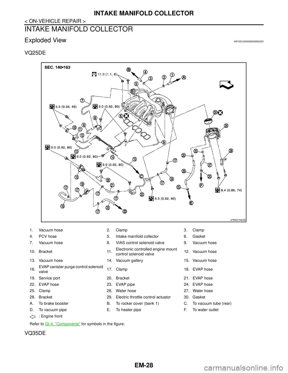
INTAKE MANIFOLD COLLECTOR
INTAKE MANIFOLD COLLECTOR
Exploded ViewINFOID:0000000003802253
VQ25DE
VQ35DE
1. Vacuum hose 2. Clamp 3. Clamp
4. PCV hose 5. Intake manifold collector 6. Gasket
7. Vacuum hose 8. VIAS control solenoid valve 9. Vacuum hose
10. Bracket 11.Electronic controlled engine mount
control solenoid valve12. Vacuum hose
13. Vacuum hose 14. Vacuum gallery 15. Vacuum hose
16.EVAP canister purge control solenoid
valve17. Clamp 18. EVAP hose
19. Service port 20. Bracket 21. EVAP hose
22. EVAP hose 23. EVAP pipe 24. EVAP hose
25. Clamp 26. Water hose 27. Water hose
28. Bracket 29. Electric throttle control actuator 30. Gasket
A. To brake booster B. To rocker cover (bank 1) C. To vacuum tube (rear)
D. To vacuum pipe E. To heater pipe F. To water outlet
: Engine front
Refer to GI-4, "
Components" for symbols in the figure.
JPBIA2194GB