2008 NISSAN TEANA wheel torque
[x] Cancel search: wheel torquePage 2479 of 5121
PREPARATION
FSU-5
< PREPARATION >
C
D
F
G
H
I
J
K
L
MA
B
FSU
N
O
P
PREPARATION
PREPARATION
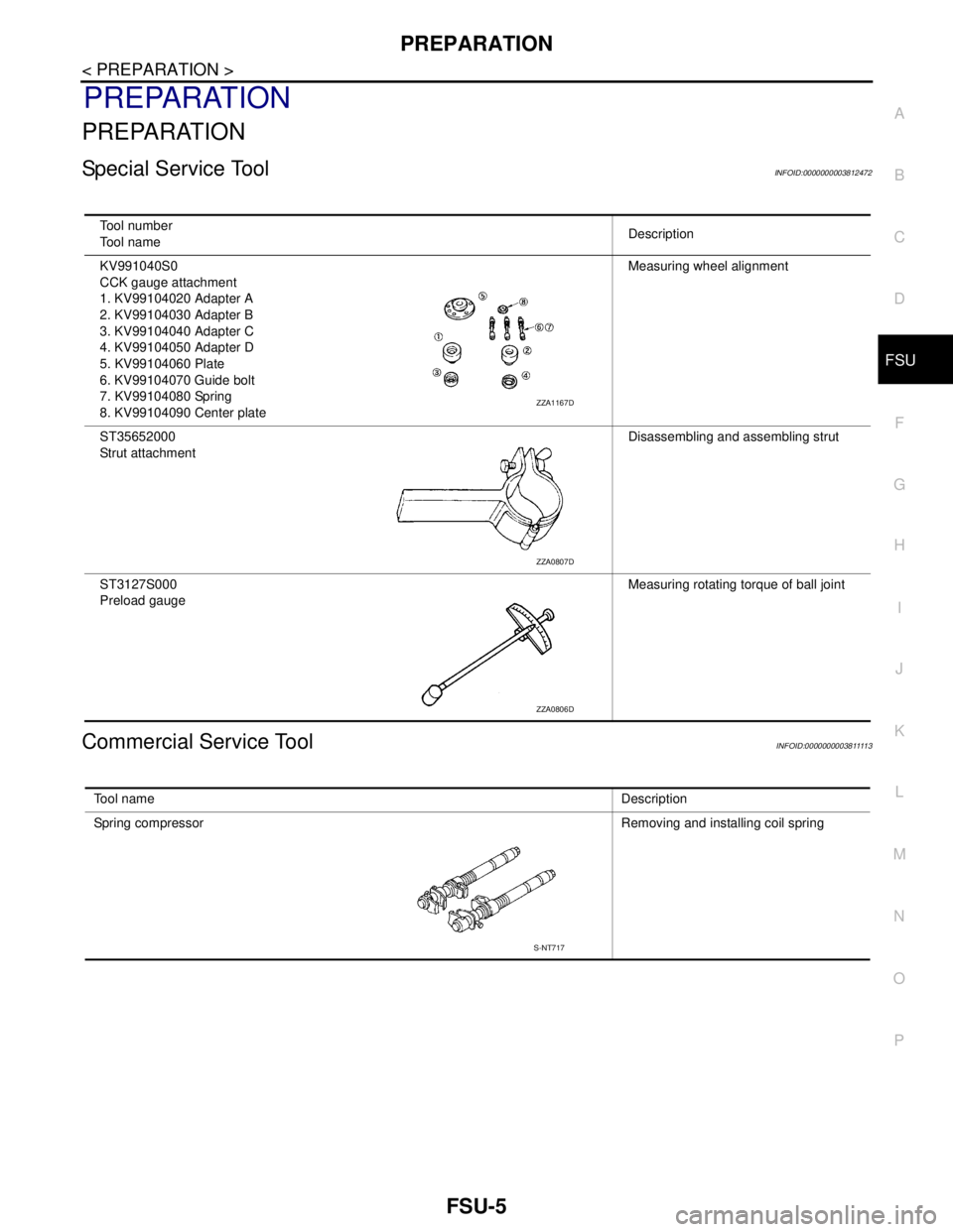
Special Service ToolINFOID:0000000003812472
Commercial Service ToolINFOID:000000000381111 3
Tool number
Tool nameDescription
KV991040S0
CCK gauge attachment
1. KV99104020 Adapter A
2. KV99104030 Adapter B
3. KV99104040 Adapter C
4. KV99104050 Adapter D
5. KV99104060 Plate
6. KV99104070 Guide bolt
7. KV99104080 Spring
8. KV99104090 Center plateMeasuring wheel alignment
ST35652000
Strut attachmentDisassembling and assembling strut
ST3127S000
Preload gaugeMeasuring rotating torque of ball joint
ZZA1167D
ZZA0807D
ZZA0806D
Tool nameDescription
Spring compressor Removing and installing coil spring
S-NT717
Page 2485 of 5121
FRONT COIL SPRING AND STRUT
FSU-11
< ON-VEHICLE REPAIR >
C
D
F
G
H
I
J
K
L
MA
B
FSU
N
O
P
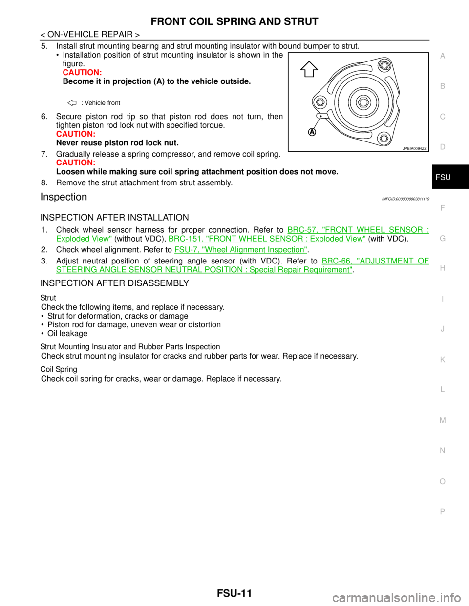
5. Install strut mounting bearing and strut mounting insulator with bound bumper to strut.
Installation position of strut mounting insulator is shown in the
figure.
CAUTION:
Become it in projection (A) to the vehicle outside.
6. Secure piston rod tip so that piston rod does not turn, then
tighten piston rod lock nut with specified torque.
CAUTION:
Never reuse piston rod lock nut.
7. Gradually release a spring compressor, and remove coil spring.
CAUTION:
Loosen while making sure coil spring attachment position does not move.
8. Remove the strut attachment from strut assembly.
InspectionINFOID:000000000381111 9
INSPECTION AFTER INSTALLATION
1. Check wheel sensor harness for proper connection. Refer to BRC-57, "FRONT WHEEL SENSOR :
Exploded View" (without VDC), BRC-151, "FRONT WHEEL SENSOR : Exploded View" (with VDC).
2. Check wheel alignment. Refer to FSU-7, "
Wheel Alignment Inspection".
3. Adjust neutral position of steering angle sensor (with VDC). Refer to BRC-66, "
ADJUSTMENT OF
STEERING ANGLE SENSOR NEUTRAL POSITION : Special Repair Requirement".
INSPECTION AFTER DISASSEMBLY
Str ut
Check the following items, and replace if necessary.
Strut for deformation, cracks or damage
Piston rod for damage, uneven wear or distortion
Oil leakage
Strut Mounting Insulator and Rubber Parts Inspection
Check strut mounting insulator for cracks and rubber parts for wear. Replace if necessary.
Coil Spring
Check coil spring for cracks, wear or damage. Replace if necessary.
: Vehicle front
JPEIA0094ZZ
Page 2486 of 5121
FSU-12
< ON-VEHICLE REPAIR >
TRANSVERSE LINK
TRANSVERSE LINK
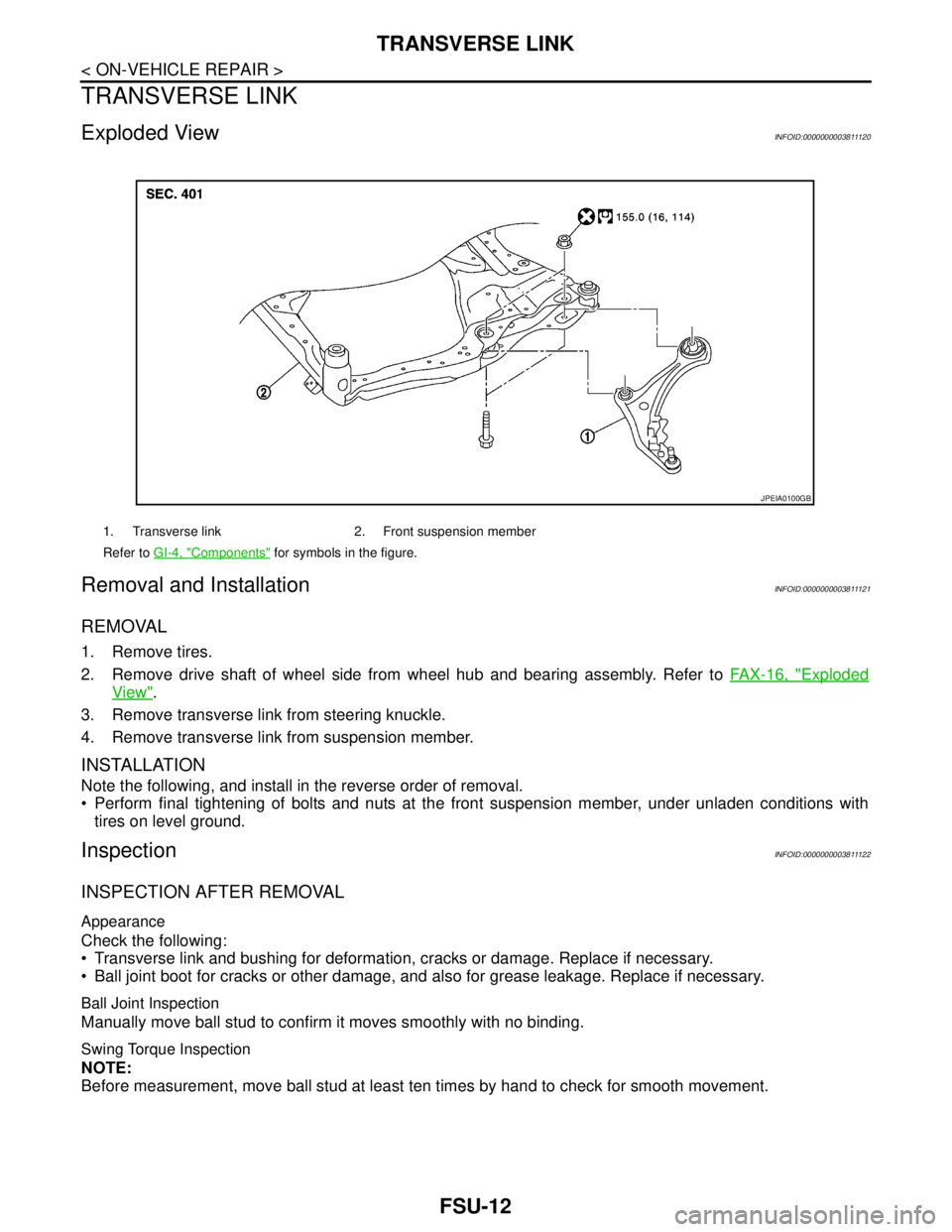
Exploded ViewINFOID:0000000003811120
Removal and InstallationINFOID:0000000003811121
REMOVAL
1. Remove tires.
2. Remove drive shaft of wheel side from wheel hub and bearing assembly. Refer to FAX-16, "
Exploded
View".
3. Remove transverse link from steering knuckle.
4. Remove transverse link from suspension member.
INSTALLATION
Note the following, and install in the reverse order of removal.
Perform final tightening of bolts and nuts at the front suspension member, under unladen conditions with
tires on level ground.
InspectionINFOID:0000000003811122
INSPECTION AFTER REMOVAL
Appearance
Check the following:
Transverse link and bushing for deformation, cracks or damage. Replace if necessary.
Ball joint boot for cracks or other damage, and also for grease leakage. Replace if necessary.
Ball Joint Inspection
Manually move ball stud to confirm it moves smoothly with no binding.
Swing Torque Inspection
NOTE:
Before measurement, move ball stud at least ten times by hand to check for smooth movement.
1. Transverse link 2. Front suspension member
Refer to GI-4, "
Components" for symbols in the figure.
JPEIA0100GB
Page 2487 of 5121
TRANSVERSE LINK
FSU-13
< ON-VEHICLE REPAIR >
C
D
F
G
H
I
J
K
L
MA
B
FSU
N
O
P
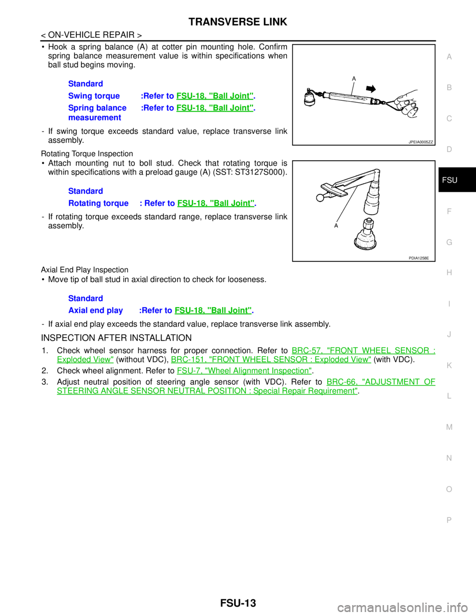
Hook a spring balance (A) at cotter pin mounting hole. Confirm
spring balance measurement value is within specifications when
ball stud begins moving.
- If swing torque exceeds standard value, replace transverse link
assembly.
Rotating Torque Inspection
Attach mounting nut to boll stud. Check that rotating torque is
within specifications with a preload gauge (A) (SST: ST3127S000).
- If rotating torque exceeds standard range, replace transverse link
assembly.
Axial End Play Inspection
Move tip of ball stud in axial direction to check for looseness.
- If axial end play exceeds the standard value, replace transverse link assembly.
INSPECTION AFTER INSTALLATION
1. Check wheel sensor harness for proper connection. Refer to BRC-57, "FRONT WHEEL SENSOR :
Exploded View" (without VDC), BRC-151, "FRONT WHEEL SENSOR : Exploded View" (with VDC).
2. Check wheel alignment. Refer to FSU-7, "
Wheel Alignment Inspection".
3. Adjust neutral position of steering angle sensor (with VDC). Refer to BRC-66, "
ADJUSTMENT OF
STEERING ANGLE SENSOR NEUTRAL POSITION : Special Repair Requirement". Standard
Swing torque :Refer to FSU-18, "
Ball Joint".
Spring balance
measurement:Refer to FSU-18, "
Ball Joint".
JPEIA0005ZZ
Standard
Rotating torque : Refer to FSU-18, "
Ball Joint".
PDIA1258E
Standard
Axial end play :Refer to FSU-18, "
Ball Joint".
Page 2492 of 5121
FSU-18
< SERVICE DATA AND SPECIFICATIONS (SDS)
SERVICE DATA AND SPECIFICATIONS (SDS)
SERVICE DATA AND SPECIFICATIONS (SDS)
SERVICE DATA AND SPECIFICATIONS (SDS)
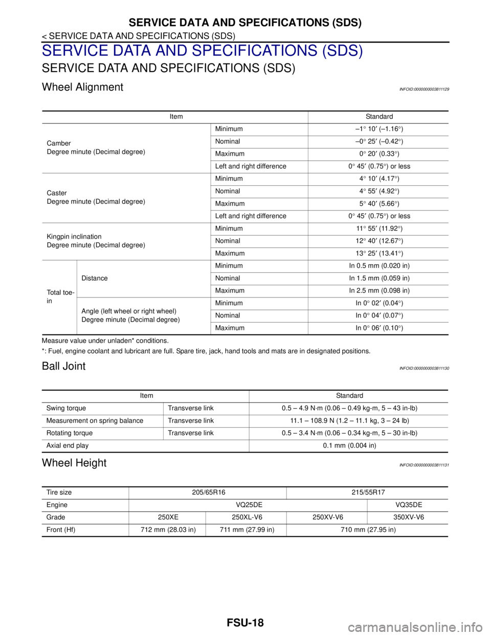
Wheel AlignmentINFOID:0000000003811129
Measure value under unladen* conditions.
*: Fuel, engine coolant and lubricant are full. Spare tire, jack, hand tools and mats are in designated positions.
Ball JointINFOID:0000000003811130
Wheel HeightINFOID:0000000003811131
Item Standard
Camber
Degree minute (Decimal degree)Minimum –1° 10′ (–1.16°)
Nominal –0° 25′ (–0.42°)
Maximum 0° 20′ (0.33°)
Left and right difference 0° 45′ (0.75°) or less
Caster
Degree minute (Decimal degree)Minimum 4° 10′ (4.17°)
Nominal 4° 55′ (4.92°)
Maximum 5° 40′ (5.66°)
Left and right difference 0° 45′ (0.75°) or less
Kingpin inclination
Degree minute (Decimal degree)Minimum 11° 55′ (11.92°)
Nominal 12° 40′ (12.67°)
Maximum 13° 25′ (13.41°)
To t a l t o e -
inDistanceMinimum In 0.5 mm (0.020 in)
Nominal In 1.5 mm (0.059 in)
Maximum In 2.5 mm (0.098 in)
Angle (left wheel or right wheel)
Degree minute (Decimal degree)Minimum In 0° 02′ (0.04°)
Nominal In 0° 04
′ (0.07°)
Maximum In 0° 06′ (0.10°)
Item Standard
Swing torque Transverse link 0.5 – 4.9 N·m (0.06 – 0.49 kg-m, 5 – 43 in-lb)
Measurement on spring balance Transverse link 11.1 – 108.9 N (1.2 – 11.1 kg, 3 – 24 lb)
Rotating torque Transverse link 0.5 – 3.4 N·m (0.06 – 0.34 kg-m, 5 – 30 in-lb)
Axial end play0.1 mm (0.004 in)
Tire size 205/65R16 215/55R17
Engine VQ25DE VQ35DE
Grade 250XE 250XL-V6 250XV-V6 350XV-V6
Front (Hf) 712 mm (28.03 in) 711 mm (27.99 in) 710 mm (27.95 in)
Page 2494 of 5121

GI-1
GENERAL INFORMATION
C
D
E
F
G
H
I
J
K
L
MB
GI
SECTION GI
N
O
P
CONTENTS
GENERAL INFORMATION
HOW TO USE THIS MANUAL ......................3
HOW TO USE THIS MANUAL ............................3
Description ................................................................3
Terms ........................................................................3
Units ..........................................................................3
Contents ....................................................................3
Relation between Illustrations and Descriptions .......4
Components ..............................................................4
HOW TO FOLLOW TROUBLE DIAGNOSES .....6
Description ................................................................6
How to Follow Test Groups in Trouble Diagnosis ......6
Key to Symbols Signifying Measurements or Pro-
cedures .....................................................................
7
HOW TO READ WIRING DIAGRAMS ................9
Connector Symbols ...................................................9
Sample/Wiring Diagram -Example- .........................10
Description ..............................................................11
ABBREVIATIONS ..............................................13
Abbreviation List ......................................................13
TIGHTENING TORQUE OF STANDARD
BOLTS ................................................................
14
Description ..............................................................14
Tightening Torque Table (New Standard Includ-
ed) ...........................................................................
14
TERMINOLOGY .................................................17
SAE J1930 Terminology List ...................................17
FEATURES OF NEW MODEL .....................21
IDENTIFICATION INFORMATION .....................21
Model Variation .......................................................21
Information About Identification or Model Code ......21
Dimensions .............................................................23
Wheels & Tires ........................................................23
PRECAUTION ..............................................24
PRECAUTIONS .................................................24
Description ...............................................................24
Precaution for Supplemental Restraint System
(SRS) "AIR BAG" and "SEAT BELT PRE-TEN-
SIONER" .................................................................
24
Precautions For Xenon Headlamp Service .............24
Precaution Necessary for Steering Wheel Rota-
tion after Battery Disconnect ...................................
24
Precaution for Procedure without Cowl Top Cover ....25
General Precautions ................................................25
Three Way Catalyst .................................................27
Multiport Fuel Injection System or Engine Control
System .....................................................................
27
Hoses ......................................................................27
Engine Oils ..............................................................28
Air Conditioning .......................................................28
Fuel ..........................................................................29
LIFTING POINT .................................................30
Commercial Service Tools .......................................30
Garage Jack and Safety Stand and 2-Pole Lift .......30
Board-On Lift ...........................................................31
TOW TRUCK TOWING .....................................32
Tow Truck Towing ...................................................32
Vehicle Recovery (Freeing a Stuck Vehicle) ...........32
BASIC INSPECTION ...................................34
SERVICE INFORMATION FOR ELECTRICAL
INCIDENT ..........................................................
34
Work Flow ................................................................34
Control Units and Electrical Parts ............................34
Intermittent Incident .................................................35
Circuit Inspection .....................................................37
CONSULT-III/GST CHECKING SYSTEM .........43
Description ...............................................................43
CONSULT-III Function and System Application*1 ....43
CONSULT-III/GST Data Link Connector (DLC)
Circuit ......................................................................
43
Page 3223 of 5121
CHASSIS MAINTENANCE
MA-35
< ON-VEHICLE MAINTENANCE >
C
D
E
F
G
H
I
J
K
L
MB
MAN
OA
CVT FLUID CONDITION
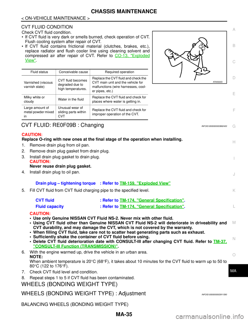
Check CVT fluid condition.
If CVT fluid is very dark or smells burned, check operation of CVT.
Flush cooling system after repair of CVT.
If CVT fluid contains frictional material (clutches, brakes, etc.),
replace radiator and flush cooler line using cleaning solvent and
compressed air after repair of CVT. Refer to CO-13, "
Exploded
View".
CVT FLUID: RE0F09B : ChangingINFOID:0000000003862430
CAUTION:
Replace O-ring with new ones at the final stage of the operation when installing.
1. Remove drain plug from oil pan.
2. Remove drain plug gasket from drain plug.
3. Install drain plug gasket to drain plug.
CAUTION:
Never reuse drain plug gasket.
4. Install drain plug to oil pan.
5. Fill CVT fluid from CVT fluid charging pipe to the specified level.
CAUTION:
Use only Genuine NISSAN CVT Fluid NS-2. Never mix with other fluid.
Using CVT fluid other than Genuine NISSAN CVT Fluid NS-2 will deteriorate in driveability and
CVT durability, and may damage the CVT, which is not covered by the warranty.
When filling CVT fluid, take care not to scatter heat generating parts such as exhaust.
Sufficiently shake the container of CVT fluid before using.
Delete CVT fluid deterioration date with CONSULT-III after changing CVT fluid. Refer to TM-37,
"CONSULT-III Function (TRANSMISSION)".
6. With the engine warmed up, drive the vehicle in an urban area.
NOTE:
When ambient temperature is 20°C (68°F), it takes about 10 minutes for the CVT fluid to warm up to 50 to
80°C (122 to 176°F).
7. Check CVT fluid level and condition.
8. Repeat steps 1 to 5 if CVT fluid has been contaminated.
WHEELS (BONDING WEIGHT TYPE)
WHEELS (BONDING WEIGHT TYPE) : AdjustmentINFOID:0000000003911590
BALANCING WHEELS (BONDING WEIGHT TYPE)
Fluid status Conceivable cause Required operation
Varnished (viscous
varnish state)CVT fluid becomes
degraded due to
high temperatures.Replace the CVT fluid and check the
CVT main unit and the vehicle for
malfunctions (wire harnesses, cool-
er pipes, etc.)
Milky white or
cloudyWater in the fluidReplace the CVT fluid and check for
places where water is getting in.
Large amount of
metal powder mixed
inUnusual wear of
sliding parts within
CVTReplace the CVT fluid and check for
improper operation of the CVT.
ATA0022D
Drain plug – tightening torque : Refer to TM-159, "Exploded View"
CVT fluid : Refer to TM-174, "General Specification".
Fluid capacity : Refer to TM-174, "
General Specification".
Page 3225 of 5121
CHASSIS MAINTENANCE
MA-37
< ON-VEHICLE MAINTENANCE >
C
D
E
F
G
H
I
J
K
L
MB
MAN
OA
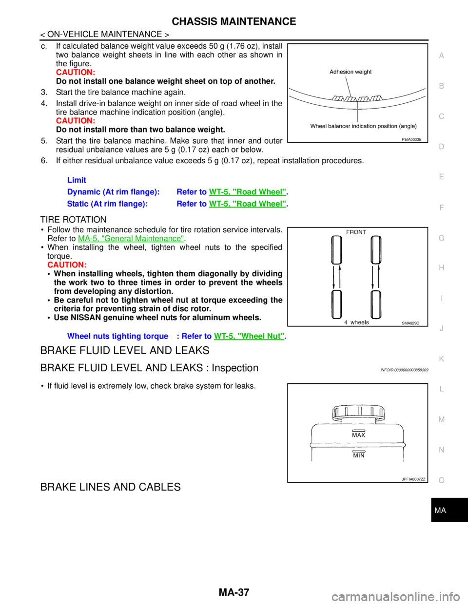
c. If calculated balance weight value exceeds 50 g (1.76 oz), install
two balance weight sheets in line with each other as shown in
the figure.
CAUTION:
Do not install one balance weight sheet on top of another.
3. Start the tire balance machine again.
4. Install drive-in balance weight on inner side of road wheel in the
tire balance machine indication position (angle).
CAUTION:
Do not install more than two balance weight.
5. Start the tire balance machine. Make sure that inner and outer
residual unbalance values are 5 g (0.17 oz) each or below.
6. If either residual unbalance value exceeds 5 g (0.17 oz), repeat installation procedures.
TIRE ROTATION
Follow the maintenance schedule for tire rotation service intervals.
Refer to MA-5, "
General Maintenance".
When installing the wheel, tighten wheel nuts to the specified
torque.
CAUTION:
When installing wheels, tighten them diagonally by dividing
the work two to three times in order to prevent the wheels
from developing any distortion.
Be careful not to tighten wheel nut at torque exceeding the
criteria for preventing strain of disc rotor.
Use NISSAN genuine wheel nuts for aluminum wheels.
BRAKE FLUID LEVEL AND LEAKS
BRAKE FLUID LEVEL AND LEAKS : InspectionINFOID:0000000003858309
If fluid level is extremely low, check brake system for leaks.
BRAKE LINES AND CABLES
Limit
Dynamic (At rim flange): Refer to WT-5, "
Road Wheel".
Static (At rim flange): Refer to WT-5, "
Road Wheel".
PEIA0033E
Wheel nuts tighting torque : Refer to WT-5, "Wheel Nut".
SMA829C
JPFIA0007ZZ