Page 611 of 5121
![NISSAN TEANA 2008 Service Manual AV
POWER SUPPLY AND GROUND CIRCUIT
AV-467
< COMPONENT DIAGNOSIS >[BOSE AUDIO WITH NAVIGATION]
C
D
E
F
G
H
I
J
K
L
MB A
O
P
Is the inspection result normal?
YES >> GO TO 3.
NO >> Check harness between NISSAN TEANA 2008 Service Manual AV
POWER SUPPLY AND GROUND CIRCUIT
AV-467
< COMPONENT DIAGNOSIS >[BOSE AUDIO WITH NAVIGATION]
C
D
E
F
G
H
I
J
K
L
MB A
O
P
Is the inspection result normal?
YES >> GO TO 3.
NO >> Check harness between](/manual-img/5/57391/w960_57391-610.png)
AV
POWER SUPPLY AND GROUND CIRCUIT
AV-467
< COMPONENT DIAGNOSIS >[BOSE AUDIO WITH NAVIGATION]
C
D
E
F
G
H
I
J
K
L
MB A
O
P
Is the inspection result normal?
YES >> GO TO 3.
NO >> Check harness between BOSE amp. and fuse.
3.CHECK GROUND CIRCUIT
1. Turn ignition switch OFF.
2. Disconnect BOSE amp. connector.
3. Check continuity between BOSE amp. harness connector and ground.
Is the inspection result normal?
YES >> INSPECTION END
NO >> Repair harness or connector.
CAMERA CONTROL UNIT
CAMERA CONTROL UNIT : Diagnosis ProcedureINFOID:0000000003765900
1.CHECK FUSE
Check for blown fuses.
Is inspection result normal?
YES >> GO TO 2.
NO >> Be sure to eliminate cause of malfunction before installing new fuse.
2.CHECK POWER SUPPLY CIRCUITS
Check voltage between camera control unit harness connector and ground.
Is inspection result normal?
YES >> GO TO 3.
NO >> Check harness between camera control unit and fuse.
3.CHECK GROUND CIRCUIT
1. Turn ignition switch OFF.
2. Disconnect camera control unit connector.
3. Check continuity between camera control unit harness connector and ground.
Is inspection result normal?
YES >> INSPECTION END
Signal name Connector No. Terminal No. Ignition switch position Voltage (Approx.)
Battery power supply B22410
OFF
Battery voltage 11
ACC power supply B225 20 ACC
Signal name Connector No. Terminal No. Ignition switch position Continuity
Ground B2247
OFF Existed
12
Power source Fuse No.
Battery 31
Ignition switch ACC 19
Signal name Connector No. Terminal No. Ignition switch position Voltage (Approx.)
Battery power supply
B25132 OFF
Battery voltage
ACC power supply 30 ACC
Signal name Connector No. Terminal No. Ignition switch position Continuity
Ground B251 31 OFF Existed
Page 612 of 5121
![NISSAN TEANA 2008 Service Manual AV-468
< COMPONENT DIAGNOSIS >[BOSE AUDIO WITH NAVIGATION]
POWER SUPPLY AND GROUND CIRCUIT
NO >> Repair harness or connector.
DVD PLAYER
DVD PLAYER : Diagnosis ProcedureINFOID:0000000003794711
1.CHE NISSAN TEANA 2008 Service Manual AV-468
< COMPONENT DIAGNOSIS >[BOSE AUDIO WITH NAVIGATION]
POWER SUPPLY AND GROUND CIRCUIT
NO >> Repair harness or connector.
DVD PLAYER
DVD PLAYER : Diagnosis ProcedureINFOID:0000000003794711
1.CHE](/manual-img/5/57391/w960_57391-611.png)
AV-468
< COMPONENT DIAGNOSIS >[BOSE AUDIO WITH NAVIGATION]
POWER SUPPLY AND GROUND CIRCUIT
NO >> Repair harness or connector.
DVD PLAYER
DVD PLAYER : Diagnosis ProcedureINFOID:0000000003794711
1.CHECK FUSE
Check for blown fuses.
Is inspection result normal?
YES >> GO TO 2.
NO >> Be sure to eliminate cause of malfunction before installing new fuse.
2.CHECK POWER SUPPLY CIRCUIT
Check voltage between DVD player harness connectors and ground.
Is inspection result normal?
YES >> GO TO 3.
NO >> Check harness between DVD player and fuse.
3.CHECK GROUND CIRCUIT
1. Turn ignition switch OFF.
2. Disconnect DVD player connectors.
3. Check continuity between DVD player harness connectors and ground.
Is inspection result normal?
YES >> INSPECTION END
NO >> Repair harness or connector.
Power source Fuse No.
Battery 31
Ignition switch ACC or ON 19
Signal name Connector No. Terminal No. Ignition switch position Voltage (Approx.)
Battery power supply
M2542OFF
Battery voltage
ACC power supply 4 ACC
Signal name Connector No. Terminal No. Ignition switch position Continuity
Ground M254 1 OFF Existed
Page 854 of 5121

BCS
POWER SUPPLY AND GROUND CIRCUIT
BCS-37
< COMPONENT DIAGNOSIS >
C
D
E
F
G
H
I
J
K
L B A
O
P N
POWER SUPPLY AND GROUND CIRCUIT
Diagnosis ProcedureINFOID:0000000003809624
1.CHECK FUSE AND FUSIBLE LINK
Check that the following fuse and fusible link are not blown.
Is the fuse fusing?
YES >> Replace the blown fuse or fusible link after repairing the affected circuit if a fuse or fusible link is
blown.
NO >> GO TO 2.
2.CHECK POWER SUPPLY CIRCUIT
1. Turn ignition switch OFF.
2. Disconnect BCM connectors.
3. Check voltage between BCM harness connector and ground.
Is the measurement value normal?
YES >> GO TO 3.
NO >> Repair harness or connector.
3.CHECK GROUND CIRCUIT
Check continuity between BCM harness connector and ground.
Does continuity exist?
YES >> INSPECTION END
NO >> Repair harness or connector.
Signal name Fuse and fusible link No.
Battery power supplyI
10
Te r m i n a l s
Vo l ta g e
(Approx.) (+) (−)
BCM
Ground Connector Terminal
M118 1
Battery voltage
M119 11
BCM
GroundContinuity
Connector Terminal
M119 13 Existed
Page 871 of 5121

BCS-54
< ECU DIAGNOSIS >
BCM (BODY CONTROL MODULE)
79
(G)GroundRoom antenna 1 (+)
(instrument panel)OutputIgnition switch
OFFWhen Intelligent Key is in
the passenger compart-
ment
When Intelligent Key is
not in the passenger
compartment
80
(G/O)GroundNATS antenna amp
(built in key slot)Input/
OutputDuring waitingIgnition switch is pressed
while inserting the key
into the key slot.Just after pressing ignition
switch. Pointer of tester should
move.
81
(O)GroundNATS antenna amp
(built in key slot)Input/
OutputDuring waitingIgnition switch is pressed
while inserting the key
into the key slot.Just after pressing ignition
switch. Pointer of tester should
move.
82
(R/B)GroundIgnition relay [fuse
block (J/B)] controlOutput Ignition switchOFF or ACC 0 V
ON Battery voltage
83
(L/O)GroundRemote keyless en-
try receiver commu-
nicationInput/
OutputDuring waiting
When operating either button on the key Te r m i n a l N o .
(Wire color)Description
ConditionVa l u e
(Approx.)
Signal nameInput/
Output +–
JMKIA0062GB
JMKIA0063GB
JMKIA0064GB
JMKIA0065GB
Page 878 of 5121

BCS
BCM (BODY CONTROL MODULE)
BCS-61
< ECU DIAGNOSIS >
C
D
E
F
G
H
I
J
K
L B A
O
P N
111
(L/Y)GroundSteering lock unit
communicationInput/
OutputSteering lockLOCK status Battery voltage
LOCK or UNLOCK
For 15 seconds after UN-
LOCKBattery voltage
15 seconds or later after
UNLOCK0 V
11 3
(P/B)Ground Optical sensor InputIgnition switch
ONWhen bright outside of
the vehicleClose to 5 V
When dark outside of the
vehicleClose to 0 V
11 5
(L)Ground Shock sensor Input Ignition switchOFF 0 V
ACC 5.0 V
ON
2.5 V
11 6
(R/W)GroundFuse check (Stop
lamp switch)Input — Battery voltage
11 8
(O/L)Ground Stop lamp switch Input Stop lamp switchOFF (Brake pedal is not
depressed)0 V
ON (Brake pedal is de-
pressed)Battery voltage
11 9
(G/W)GroundFront door lock as-
sembly driver side
(unlock sensor)Input Driver doorLOCK status (unlock sen-
sor switch OFF)
1.1 V
UNLOCK status (unlock
sensor switch ON)0 V
121
(Y)Ground Key slot switch InputWhen the key is inserted into key slot Battery voltage
When the key is not inserted into key slot 0 V
122
(V/R)Ground ACC feedback Input Ignition switchOFF 0 V
ACC or ON Battery voltage
123
(G/W)Ground IGN feedback Input Ignition switchOFF or ACC 0 V
ON Battery voltage Te r m i n a l N o .
(Wire color)Description
ConditionVa l u e
(Approx.)
Signal nameInput/
Output +–
JMKIA0066GB
JPMIA1034GB
JPMIA0012GB
Page 1108 of 5121

CHG-10
< COMPONENT DIAGNOSIS >
L TERMINAL CIRCUIT (OPEN)
L TERMINAL CIRCUIT (OPEN)
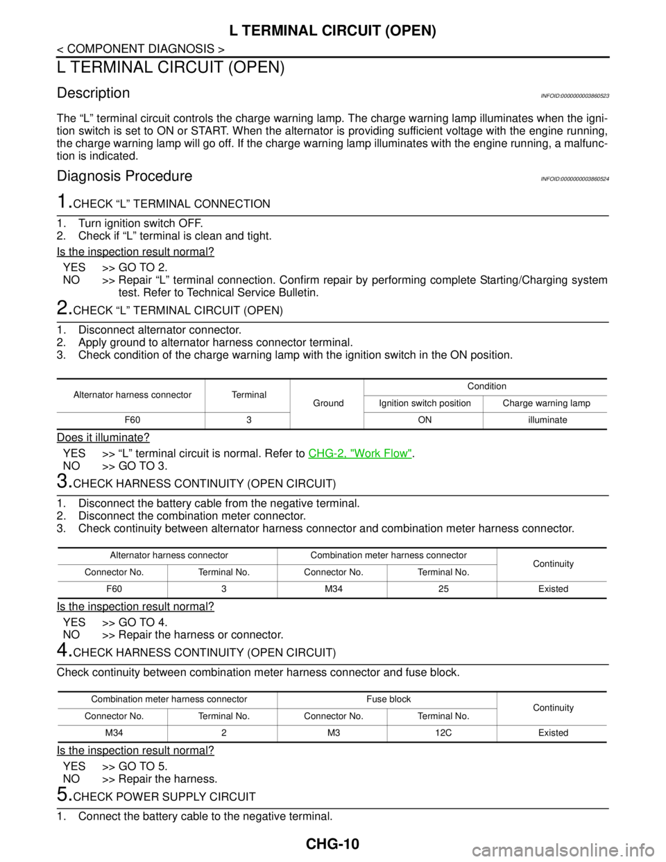
DescriptionINFOID:0000000003860523
The “L” terminal circuit controls the charge warning lamp. The charge warning lamp illuminates when the igni-
tion switch is set to ON or START. When the alternator is providing sufficient voltage with the engine running,
the charge warning lamp will go off. If the charge warning lamp illuminates with the engine running, a malfunc-
tion is indicated.
Diagnosis ProcedureINFOID:0000000003860524
1.CHECK “L” TERMINAL CONNECTION
1. Turn ignition switch OFF.
2. Check if “L” terminal is clean and tight.
Is the inspection result normal?
YES >> GO TO 2.
NO >> Repair “L” terminal connection. Confirm repair by performing complete Starting/Charging system
test. Refer to Technical Service Bulletin.
2.CHECK “L” TERMINAL CIRCUIT (OPEN)
1. Disconnect alternator connector.
2. Apply ground to alternator harness connector terminal.
3. Check condition of the charge warning lamp with the ignition switch in the ON position.
Does it illuminate?
YES >> “L” terminal circuit is normal. Refer to CHG-2, "Work Flow".
NO >> GO TO 3.
3.CHECK HARNESS CONTINUITY (OPEN CIRCUIT)
1. Disconnect the battery cable from the negative terminal.
2. Disconnect the combination meter connector.
3. Check continuity between alternator harness connector and combination meter harness connector.
Is the inspection result normal?
YES >> GO TO 4.
NO >> Repair the harness or connector.
4.CHECK HARNESS CONTINUITY (OPEN CIRCUIT)
Check continuity between combination meter harness connector and fuse block.
Is the inspection result normal?
YES >> GO TO 5.
NO >> Repair the harness.
5.CHECK POWER SUPPLY CIRCUIT
1. Connect the battery cable to the negative terminal.
Alternator harness connector Terminal
GroundCondition
Ignition switch position Charge warning lamp
F60 3 ON illuminate
Alternator harness connector Combination meter harness connector
Continuity
Connector No. Terminal No. Connector No. Terminal No.
F60 3 M34 25 Existed
Combination meter harness connector Fuse block
Continuity
Connector No. Terminal No. Connector No. Terminal No.
M34 2 M3 12C Existed
Page 1111 of 5121

CHG
S TERMINAL CIRCUIT
CHG-13
< COMPONENT DIAGNOSIS >
C
D
E
F
G
H
I
J
K
L B A
O
P N
S TERMINAL CIRCUIT
DescriptionINFOID:0000000003860527
The output voltage of the alternator is controlled by the IC voltage regulator at the “S” terminal detecting the
input voltage.
The “S” terminal circuit detects the battery voltage to adjust the alternator output voltage with the IC voltage
regulator.
Diagnosis ProcedureINFOID:0000000003860528
1.CHECK “S” TERMINAL CONNECTION
1. Turn ignition switch OFF.
2. Check if “S” terminal is clean and tight.
Is the inspection result normal?
YES >> GO TO 2.
NO >> Repair “S” terminal connection. Confirm repair by performing complete Starting/Charging system
test. Refer to Technical Service Bulletin.
2.CHECK “S” TERMINAL CIRCUIT
Check voltage between alternator harness connector and ground.
Is the inspection result normal?
YES >> Refer to CHG-2, "Work Flow".
NO >> Check harness for open between alternator and fuse.
Te r m i n a l s
Voltage (Approx.) (+)
(–)
Alternator harness connector Terminal
F60 4 Ground Battery voltage
Page 1118 of 5121

CHG-20
< ON-VEHICLE MAINTENANCE >
CHARGING SYSTEM PRELIMINARY INSPECTION
ON-VEHICLE MAINTENANCE
CHARGING SYSTEM PRELIMINARY INSPECTION
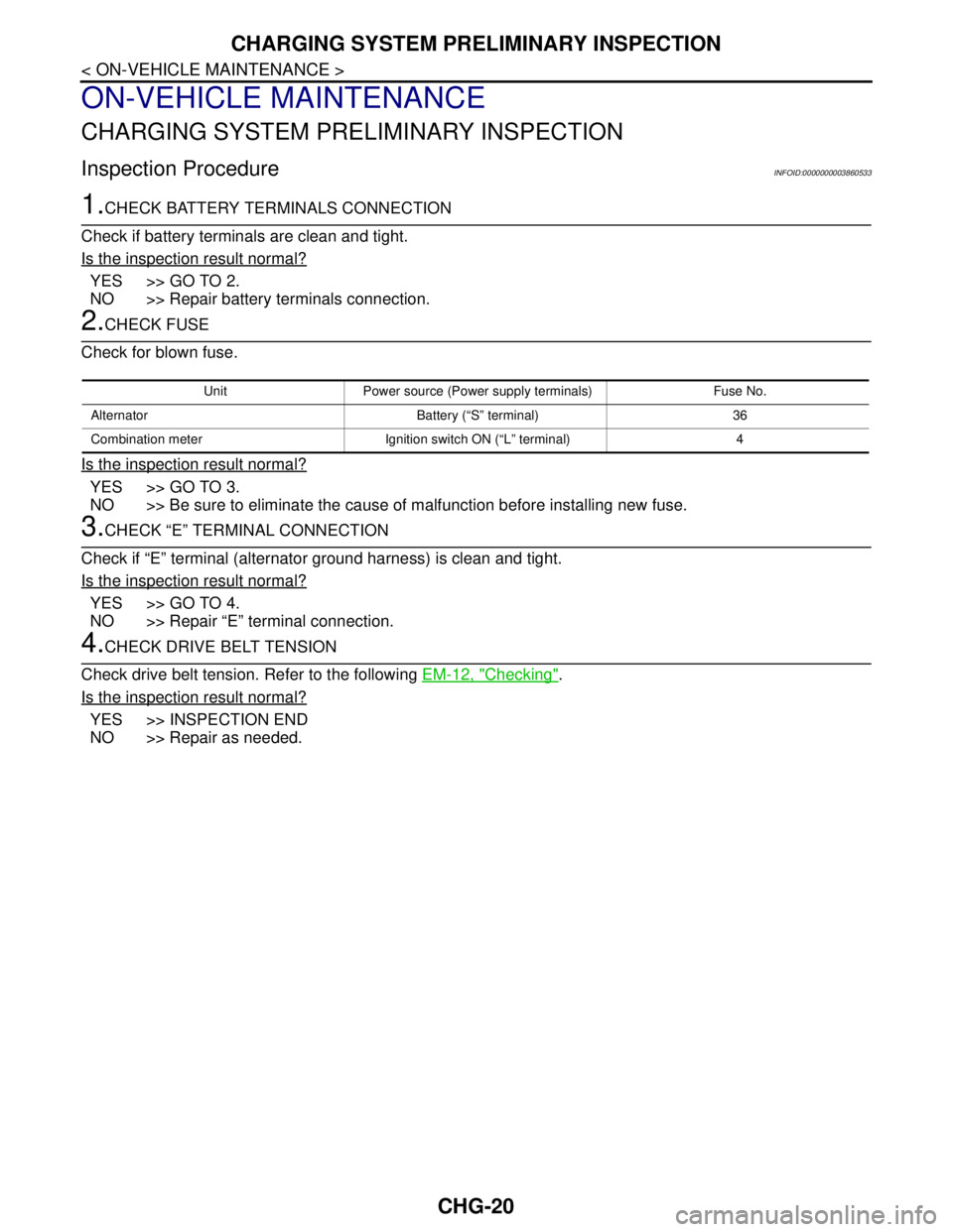
Inspection ProcedureINFOID:0000000003860533
1.CHECK BATTERY TERMINALS CONNECTION
Check if battery terminals are clean and tight.
Is the inspection result normal?
YES >> GO TO 2.
NO >> Repair battery terminals connection.
2.CHECK FUSE
Check for blown fuse.
Is the inspection result normal?
YES >> GO TO 3.
NO >> Be sure to eliminate the cause of malfunction before installing new fuse.
3.CHECK “E” TERMINAL CONNECTION
Check if “E” terminal (alternator ground harness) is clean and tight.
Is the inspection result normal?
YES >> GO TO 4.
NO >> Repair “E” terminal connection.
4.CHECK DRIVE BELT TENSION
Check drive belt tension. Refer to the following EM-12, "
Checking".
Is the inspection result normal?
YES >> INSPECTION END
NO >> Repair as needed.
Unit Power source (Power supply terminals) Fuse No.
Alternator Battery (“S” terminal) 36
Combination meter Ignition switch ON (“L” terminal) 4