2008 NISSAN TEANA alarm
[x] Cancel search: alarmPage 4035 of 5121
![NISSAN TEANA 2008 Service Manual SEC-26
< FUNCTION DIAGNOSIS >[INTELLIGENT KEY SYSTEM]
DIAGNOSIS SYSTEM (BCM)
DATA MONITOR
WORK SUPPORT
ACTIVE TEST
Diagnosis mode Function Description
WORK SUPPORT Changes the setting for each system NISSAN TEANA 2008 Service Manual SEC-26
< FUNCTION DIAGNOSIS >[INTELLIGENT KEY SYSTEM]
DIAGNOSIS SYSTEM (BCM)
DATA MONITOR
WORK SUPPORT
ACTIVE TEST
Diagnosis mode Function Description
WORK SUPPORT Changes the setting for each system](/manual-img/5/57391/w960_57391-4034.png)
SEC-26
< FUNCTION DIAGNOSIS >[INTELLIGENT KEY SYSTEM]
DIAGNOSIS SYSTEM (BCM)
DATA MONITOR
WORK SUPPORT
ACTIVE TEST
Diagnosis mode Function Description
WORK SUPPORT Changes the setting for each system function.
DATA MONITOR The BCM input/output signals are displayed.
ACTIVE TEST The signals used to activate each device are forcibly supplied from BCM.
Monitored Item Description
REQ SW -DR Indicates [ON/OFF] condition of door request switch (driver side).
REQ SW -AS Indicates [ON/OFF] condition of door request switch (passenger side).
REQ SW -RRNOTE:
This is displayed even when it is not equipped.
REQ SW -RLNOTE:
This is displayed even when it is not equipped.
REQ SW -BD/TR Indicates [ON/OFF] condition of trunk lid opener request switch.
PUSH SW Indicates [ON/OFF] condition of push-button ignition switch
UNLK SEN -DR Indicates [ON/OFF] condition of driver door UNLOCK status.
KEY SW -SLOT Indicates [ON/OFF] condition of key slot.
DOOR SW-DR Indicates [ON/OFF] condition of front door switch (driver side).
DOOR SW-AS Indicates [ON/OFF] condition of front door switch (passenger side).
DOOR SW-RR Indicates [ON/OFF] condition of rear door switch RH.
DOOR SW-RL Indicates [ON/OFF] condition of rear door switch LH.
DOOR SW-BKNOTE:
This is displayed even when it is not equipped.
CDL LOCK SW Indicates [ON/OFF] condition of lock signal from door lock/unlock switch.
CDL UNLOCK SW Indicates [ON/OFF] condition of unlock signal from door lock/unlock switch.
KEY CYL LK-SWNOTE:
This is displayed even when it is not equipped.
KEY CYL UN-SWNOTE:
This is displayed even when it is not equipped.
KEY CYL SW-TRNOTE:
This is displayed even when it is not equipped.
TR/BD OPEN SW Indicates [ON/OFF] condition of trunk lid opener switch.
TRNK/HAT MNTR Indicates [ON/OFF] condition of trunk room lamp switch.
RKE-LOCK Indicates [ON/OFF] condition of LOCK signal from Intelligent Key.
RKE-UNLOCK Indicates [ON/OFF] condition of UNLOCK signal from Intelligent Key.
RKE-TR/BD Indicates [ON/OFF] condition of TRUNK LID OPEN signal from Intelligent Key.
Test Item Description
SECURITY ALARM SET This mode is able to confirm and change security alarm ON-OFF setting.
THEFT ALM TRGThe switch which triggered vehicle security alarm is recorded. This mode is able to confirm and
erase the record of vehicle security alarm. The trigger data can be erased by touching “CLEAR” on
CONSULT-III screen.
Page 4201 of 5121
![NISSAN TEANA 2008 Service Manual S E C -192
< SYMPTOM DIAGNOSIS >[INTELLIGENT KEY SYSTEM]
SECURITY CONTROL SYSTEM
SYMPTOM DIAGNOSIS
SECURITY CONTROL SYSTEM
Symptom TableINFOID:0000000003815090
The engine start function, door lock fun NISSAN TEANA 2008 Service Manual S E C -192
< SYMPTOM DIAGNOSIS >[INTELLIGENT KEY SYSTEM]
SECURITY CONTROL SYSTEM
SYMPTOM DIAGNOSIS
SECURITY CONTROL SYSTEM
Symptom TableINFOID:0000000003815090
The engine start function, door lock fun](/manual-img/5/57391/w960_57391-4200.png)
S E C -192
< SYMPTOM DIAGNOSIS >[INTELLIGENT KEY SYSTEM]
SECURITY CONTROL SYSTEM
SYMPTOM DIAGNOSIS
SECURITY CONTROL SYSTEM
Symptom TableINFOID:0000000003815090
The engine start function, door lock function, power distribution system and NATS-IVIS/NVIS in the Intelligent
Key system are closely related to each other regarding control. Narrow down the functional area in question
by performing following table to identify which function is malfunctioning. The vehicle security function can
operate only when the door lock and power distribution system are operating normally. Therefore, it is easy to
identify any factor unique to the vehicle security system by performing following table.
Use the chart below to help you find the cause of the symptom. The numbers indicate the order of the inspec-
tion.
NOTE:
Before starting vehicle security system operation check, the following conditions must be met.
Open front windows
Turn ignition switch OFF
Pull out Intelligent Key from key slot.
NO. Function Operation condition Symptom Diagnostic ItemReference
page
1INTELLIGENT
KEY SYSTEM/
DOOR LOCK
FUNCTIONLock/unlock door with door re-
quest switch.
(Intelligent Key is into the out-
side key antenna detection ar-
ea)Door does not lock/unlock —DLK-158
2POWER DIS-
TRIBUTION
FUNCTIONPress push-button ignition
switch under the following con-
dition.
Selector lever position is in
the P or N position.
Do not depress brake pedal.Push-button ignition switch is
not operated—PCS-124
3INTELLIGENT
KEY SYSTEM/
ENGINE START
FUNCTIONStart engine with Intelligent Key
into the vehicle (inside key an-
tenna detection area)Engine can not start with Intel-
ligent Key—SEC-193
4Open the door after ignition
switch is turned ON to OFF.Steering is not locked —SEC-194
5NISSAN VEHI-
CLE IMMOBI-
LIZER
SYSTEM-NATS
FUNCTIONStart engine with Intelligent Key
into the key slot.Engine can not start (Intelli-
gent Key into the key slot)—SEC-195
6Insert Intelligent Key into the
key slot.Key slot indicator does not illu-
minate—SEC-201
7VEHICLE SE-
CURITY SYS-
TEMLock all doors with Intelligent
Key or door request switchVehicle security system can
not be setIntelligent keySEC-197
Door request switchSEC-197
Lock all doors with Intelligent
Key or door request switchSecurity indicator lamp does
not turn ON—SEC-196
In the armed phase, open the
doorVehicle security alarm does
not activate—SEC-199
When alarm sounds, press In-
telligent Key button
Vehicle security system can
not be canceledIntelligent KeySEC-200
When alarm sounds, press door
request switchDoor request switchSEC-200
8POWER DIS-
TRIBUTION
FUNCTIONPress push-button ignition
switch under the following con-
ditions.
Selector lever position is in
the P or N position.
Do not depress brake pedal.Push-button ignition switch
position indicator does not
turn on —PCS-125
Page 4208 of 5121
![NISSAN TEANA 2008 Service Manual VEHICLE SECURITY ALARM DOES NOT ACTIVATE
SEC-199
< SYMPTOM DIAGNOSIS >[INTELLIGENT KEY SYSTEM]
C
D
E
F
G
H
I
J
L
MA
B
SEC
N
O
P
VEHICLE SECURITY ALARM DOES NOT ACTIVATE
DescriptionINFOID:0000000003815 NISSAN TEANA 2008 Service Manual VEHICLE SECURITY ALARM DOES NOT ACTIVATE
SEC-199
< SYMPTOM DIAGNOSIS >[INTELLIGENT KEY SYSTEM]
C
D
E
F
G
H
I
J
L
MA
B
SEC
N
O
P
VEHICLE SECURITY ALARM DOES NOT ACTIVATE
DescriptionINFOID:0000000003815](/manual-img/5/57391/w960_57391-4207.png)
VEHICLE SECURITY ALARM DOES NOT ACTIVATE
SEC-199
< SYMPTOM DIAGNOSIS >[INTELLIGENT KEY SYSTEM]
C
D
E
F
G
H
I
J
L
MA
B
SEC
N
O
P
VEHICLE SECURITY ALARM DOES NOT ACTIVATE
DescriptionINFOID:0000000003815105
Before performing the diagnosis in the following table, check “Work Flow”. Refer to SEC-5, "Work Flow".
Diagnosis ProcedureINFOID:0000000003815106
1.CHECK CONDITION OF ALARM
Operate alarm.
Which alarm does not operate?
Hazard warning lamp and horn>>GO TO 2.
Hazard warning lamp>>GO TO 5.
Horn >> GO TO 6.
2.CHECK DOOR SWITCH
Check door switch.
Refer to DLK-57, "
ComponentFunctionCheck".
Is the inspection result normal?
YES >> GO TO 3.
NO >> Replace the malfunctioning door switch
3.CHECK TRUNK ROOM LAMP SWITCH
Check trunk lid lock assembly (trunk room lamp switch).
Refer to DLK-57, "
ComponentFunctionCheck".
Is the inspection result normal?
YES >> GO TO 4.
NO >> Repair or replace the malfunctioning parts.
4.CHECK HOOD SWITCH
Check hood switch.
Refer to SEC-113, "
ComponentFunctionCheck".
Is the inspection result normal?
YES >> GO TO 7.
NO >> Repair or replace the malfunctioning parts.
5.CHECK HAZARD WARNING LAMP
Check hazard warning lamp operation.
Refer to SEC-120, "
ComponentFunctionCheck".
Is the inspection result normal?
YES >> GO TO 7.
NO >> Repair or replace malfunctioning parts.
6.CHECK HORN
Check horn.
Refer to SEC-118, "
ComponentFunctionCheck".
Is the inspection result normal?
YES >> GO TO 7.
NO >> Repair or replace malfunctioning parts.
7.CONFIRM THE OPERATION
Confirm the operation again.
Is the result normal?
YES >> Check intermittent incident. Refer to GI-35, "Intermittent Incident".
NO >> GO TO 1.
Page 4935 of 5121

WCS
WARNING CHIME SYSTEM
WCS-5
< FUNCTION DIAGNOSIS >
C
D
E
F
G
H
I
J
K
L
MB A
O
P
FUNCTION DIAGNOSIS
WARNING CHIME SYSTEM
WARNING CHIME SYSTEM
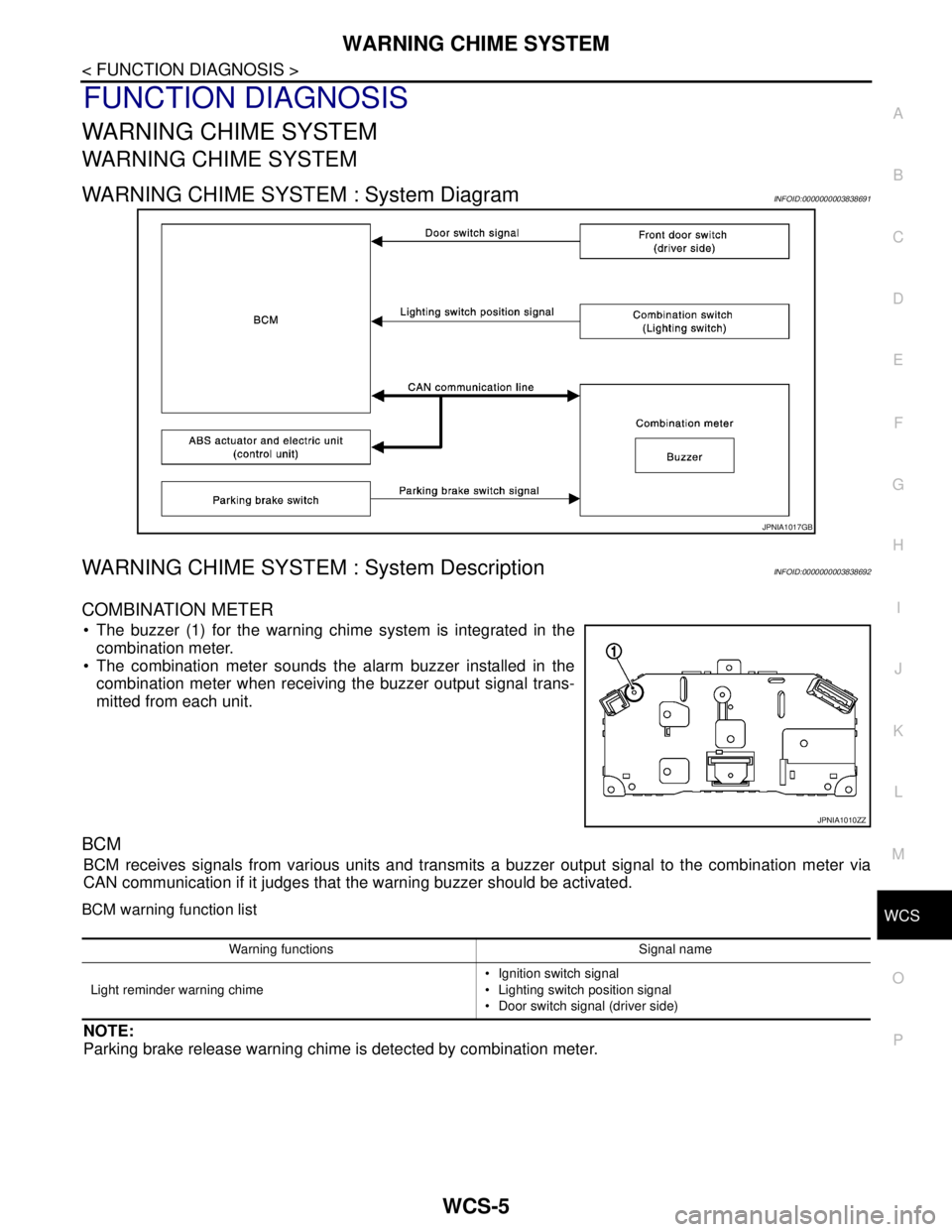
WARNING CHIME SYSTEM : System DiagramINFOID:0000000003838691
WARNING CHIME SYSTEM : System DescriptionINFOID:0000000003838692
COMBINATION METER
The buzzer (1) for the warning chime system is integrated in the
combination meter.
The combination meter sounds the alarm buzzer installed in the
combination meter when receiving the buzzer output signal trans-
mitted from each unit.
BCM
BCM receives signals from various units and transmits a buzzer output signal to the combination meter via
CAN communication if it judges that the warning buzzer should be activated.
BCM warning function list
NOTE:
Parking brake release warning chime is detected by combination meter.
JPNIA1017GB
JPNIA1010ZZ
Warning functions Signal name
Light reminder warning chime Ignition switch signal
Lighting switch position signal
Door switch signal (driver side)
Page 4951 of 5121

WCS
METER BUZZER CIRCUIT
WCS-21
< COMPONENT DIAGNOSIS >
C
D
E
F
G
H
I
J
K
L
MB A
O
P
METER BUZZER CIRCUIT
DescriptionINFOID:0000000003838708
The buzzer for warning chime system is installed in the combination meter.
The combination meter sounds the alarm buzzer based on the signals transmitted from various units.
Component Function CheckINFOID:0000000003838709
1.CHECK OPERATION OF METER BUZZER
1. Select “BUZZER” of “BCM” on CONSULT-III.
2. Perform “LIGHT WARN ALM” of “Active Test”.
Does meter buzzer beep?
YES >> INSPECTION END
NO >> GO TO 2.
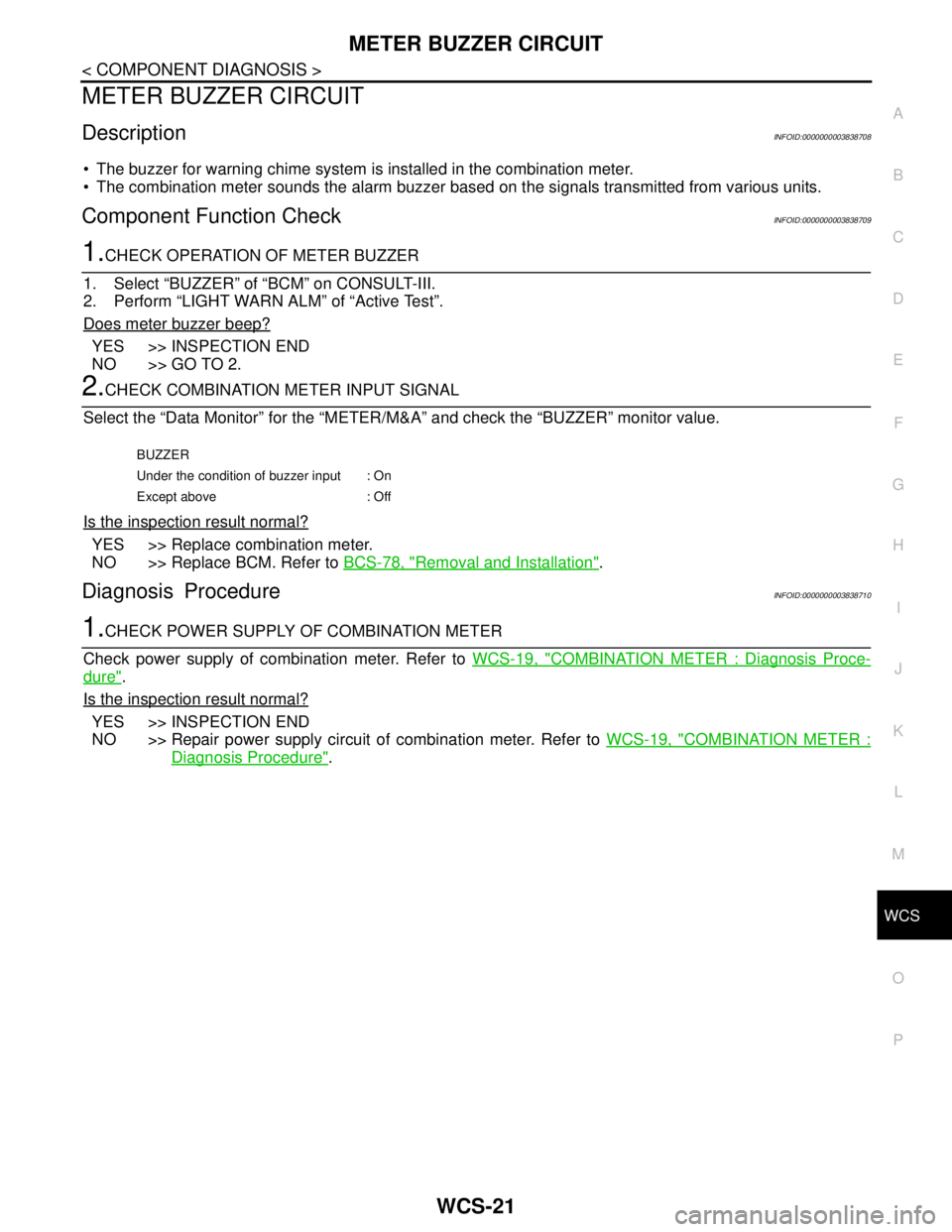
2.CHECK COMBINATION METER INPUT SIGNAL
Select the “Data Monitor” for the “METER/M&A” and check the “BUZZER” monitor value.
Is the inspection result normal?
YES >> Replace combination meter.
NO >> Replace BCM. Refer to BCS-78, "
Removal and Installation".
Diagnosis ProcedureINFOID:0000000003838710
1.CHECK POWER SUPPLY OF COMBINATION METER
Check power supply of combination meter. Refer to WCS-19, "
COMBINATION METER : Diagnosis Proce-
dure".
Is the inspection result normal?
YES >> INSPECTION END
NO >> Repair power supply circuit of combination meter. Refer to WCS-19, "
COMBINATION METER :
Diagnosis Procedure".
BUZZER
Under the condition of buzzer input : On
Except above : Off