Page 2059 of 5121
![NISSAN TEANA 2008 Service Manual EXL-30
< FUNCTION DIAGNOSIS >[XENON TYPE]
DIAGNOSIS SYSTEM (BCM)
ACTIVE TEST
FLASHER
FLASHER : CONSULT-III Function (BCM - FLASHER)INFOID:0000000003773549
WORK SUPPORT
*: Factory setting
DATA MONITOR](/manual-img/5/57391/w960_57391-2058.png "NISSAN TEANA 2008 Service Manual EXL-30
< FUNCTION DIAGNOSIS >[XENON TYPE]
DIAGNOSIS SYSTEM (BCM)
ACTIVE TEST
FLASHER
FLASHER : CONSULT-III Function (BCM - FLASHER)INFOID:0000000003773549
WORK SUPPORT
*: Factory setting
DATA MONITOR")
EXL-30
< FUNCTION DIAGNOSIS >[XENON TYPE]
DIAGNOSIS SYSTEM (BCM)
ACTIVE TEST
FLASHER
FLASHER : CONSULT-III Function (BCM - FLASHER)INFOID:0000000003773549
WORK SUPPORT
*: Factory setting
DATA MONITOR
DOOR SW-RR
[On/Off]The switch status input from rear door switch RH
DOOR SW- RL
[On/Off]The switch status input from rear door switch LH
DOOR SW-BK
[On/Off]NOTE:
The item is indicated, but not monitored.
OPTICAL SENSOR
[V]The value of exterior brightness voltage input from the optical sensor Monitor item
[Unit]Description
Test item Operation Description
TA I L L A M POnTransmits the position light request signal to IPDM E/R with CAN com-
munication to turn the tail lamp ON.
Off Stops the position light request signal transmission.
HEAD LAMPHiTransmits the high beam request signal with CAN communication to turn
the headlamp (HI).
LowTransmits the low beam request signal with CAN communication to turn
the headlamp (LO).
Off Stops the high & low beam request signal transmission.
FR FOG LAMPOnTransmits the front fog lights request signal to IPDM E/R with CAN com-
munication to turn the front fog lamp ON.
Off Stops the front fog lights request signal transmission.
RR FOG LAMPOn Outputs the voltage to turn the rear fog lamp ON.
Transmits the rear fog lamp status signal to the combination meter with
CAN communication to turn the rear fog lamp indicator lamp ON.
Off Stops the voltage to turn the rear fog lamp OFF.
Stops the rear fog lamp status signal transmission.
DAYTIME RUNNING LIGHTOn
NOTE:
The item is indicated, but cannot be tested.
Off
CORNERING LAMPRH
NOTE:
The item is indicated, but cannot be tested. LH
Off
ILL DIM SIGNALOn
NOTE:
The item is indicated, but cannot be tested.
Off
Service item Setting item Setting
HAZARD ANSWER
BACKLock Only* With locking only
Sets the hazard warning lamp answer back function
when the door is lock/unlock with the request switch or
the key fob. Unlk Only With unlocking only
Lock/Unlk With locking/unlocking
Off Without the function
Page 2246 of 5121
![NISSAN TEANA 2008 Service Manual DIAGNOSIS SYSTEM (BCM)
EXL-217
< FUNCTION DIAGNOSIS >[HALOGEN TYPE]
C
D
E
F
G
H
I
J
K
MA
B
EXL
N
O
P
ACTIVE TEST
FLASHER
FLASHER : CONSULT-III Function (BCM - FLASHER)INFOID:0000000003894309
WORK SUPP](/manual-img/5/57391/w960_57391-2245.png "NISSAN TEANA 2008 Service Manual DIAGNOSIS SYSTEM (BCM)
EXL-217
< FUNCTION DIAGNOSIS >[HALOGEN TYPE]
C
D
E
F
G
H
I
J
K
MA
B
EXL
N
O
P
ACTIVE TEST
FLASHER
FLASHER : CONSULT-III Function (BCM - FLASHER)INFOID:0000000003894309
WORK SUPP")
DIAGNOSIS SYSTEM (BCM)
EXL-217
< FUNCTION DIAGNOSIS >[HALOGEN TYPE]
C
D
E
F
G
H
I
J
K
MA
B
EXL
N
O
P
ACTIVE TEST
FLASHER
FLASHER : CONSULT-III Function (BCM - FLASHER)INFOID:0000000003894309
WORK SUPPORT
*: Factory setting
DATA MONITOR
DOOR SW-RR
[On/Off]The switch status input from rear door switch RH
DOOR SW- RL
[On/Off]The switch status input from rear door switch LH
DOOR SW-BK
[On/Off]NOTE:
The item is indicated, but not monitored.
OPTICAL SENSOR
[V]The value of exterior brightness voltage input from the optical sensor Monitor item
[Unit]Description
Test item Operation Description
TA I L L A M POnTransmits the position light request signal to IPDM E/R with CAN com-
munication to turn the tail lamp ON.
Off Stops the position light request signal transmission.
HEAD LAMPHiTransmits the high beam request signal with CAN communication to turn
the headlamp (HI).
LowTransmits the low beam request signal with CAN communication to turn
the headlamp (LO).
Off Stops the high & low beam request signal transmission.
FR FOG LAMPOnTransmits the front fog lights request signal to IPDM E/R with CAN com-
munication to turn the front fog lamp ON.
Off Stops the front fog lights request signal transmission.
RR FOG LAMPOn Outputs the voltage to turn the rear fog lamp ON.
Transmits the rear fog lamp status signal to the combination meter with
CAN communication to turn the rear fog lamp indicator lamp ON.
Off Stops the voltage to turn the rear fog lamp OFF.
Stops the rear fog lamp status signal transmission.
DAYTIME RUNNING LIGHTOn
NOTE:
The item is indicated, but cannot be tested.
Off
CORNERING LAMPRH
NOTE:
The item is indicated, but cannot be tested. LH
Off
ILL DIM SIGNALOn
NOTE:
The item is indicated, but cannot be tested.
Off
Service item Setting item Setting
HAZARD ANSWER
BACKLock Only* With locking only
Sets the hazard warning lamp answer back function
when the door is lock/unlock with the request switch or
the key fob. Unlk Only With unlocking only
Lock/Unlk With locking/unlocking
Off Without the function
Page 2534 of 5121
SERVICE INFORMATION FOR ELECTRICAL INCIDENT
GI-41
< BASIC INSPECTION >
C
D
E
F
G
H
I
J
K
L
MB
GI
N
O
P
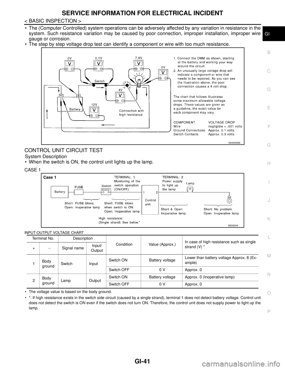
The (Computer Controlled) system operations can be adversely affected by any variation in resistance in the
system. Such resistance variation may be caused by poor connection, improper installation, improper wire
gauge or corrosion.
The step by step voltage drop test can identify a component or wire with too much resistance.
CONTROL UNIT CIRCUIT TEST
System Description
When the switch is ON, the control unit lights up the lamp.
CASE 1
INPUT-OUTPUT VOLTAGE CHART
The voltage value is based on the body ground.
*: If high resistance exists in the switch side circuit (caused by a single strand), terminal 1 does not detect battery voltage. Control unit
does not detect the switch is ON even if the switch does not turn ON. Therefore, the control unit does not supply power to light up the
lamp.
SAIA0258E
Terminal No. Description
Condition Value (Approx.)In case of high resistance such as single
strand (V) *
+−Signal nameInput/
Output
1Body
groundSwitch InputSwitch ON Battery voltageLower than battery voltage Approx. 8 (Ex-
ample)
Switch OFF 0 V Approx. 0
2Body
groundLamp OutputSwitch ON Battery voltage Approx. 0 (Inoperative lamp)
Switch OFF 0 V Approx. 0
MGI034A
Page 4485 of 5121
![NISSAN TEANA 2008 Service Manual TM-12
< BASIC INSPECTION >[CVT: RE0F09B]
INSPECTION AND ADJUSTMENT
INSPECTION AND ADJUSTMENT
ADDITIONAL SERVICE WHEN REPLACING CONTROL UNIT
ADDITIONAL SERVICE WHEN REPLACING CONTROL UNIT : Precaution](/manual-img/5/57391/w960_57391-4484.png "NISSAN TEANA 2008 Service Manual TM-12
< BASIC INSPECTION >[CVT: RE0F09B]
INSPECTION AND ADJUSTMENT
INSPECTION AND ADJUSTMENT
ADDITIONAL SERVICE WHEN REPLACING CONTROL UNIT
ADDITIONAL SERVICE WHEN REPLACING CONTROL UNIT : Precaution")
TM-12
< BASIC INSPECTION >[CVT: RE0F09B]
INSPECTION AND ADJUSTMENT
INSPECTION AND ADJUSTMENT
ADDITIONAL SERVICE WHEN REPLACING CONTROL UNIT
ADDITIONAL SERVICE WHEN REPLACING CONTROL UNIT : Precaution for TCM
and CVT Assembly Replacement
INFOID:0000000003848916
CAUTION:
• Check if new data (Unit ID) are entered correctly after replacing CVT assembly and erasing data in
TCM. (Connect CONSULT-III, and then turn ignition switch OFF.)
When replacing CVT assembly or TCM, refer to the pattern table below and erase the EEPROM in the
TCM if necessary.
EEPROM ERASING PATTERNS
METHOD FOR ERASING THE EEPROM IN THE TCM
1. Turn ignition switch ON.
2. Move selector lever to “R” position.
3. Perform “Self-Diagnostic Results” mode for “TRANSMISSION”.
4. Press the brake pedal and turn the brake switch ON.
5. Press the accelerator pedal (0.5/8 - 4/8 throttle) not to exceed the half, and hold it in the half or less open
position. (This will set the closed throttle position signal to OFF and the wide open throttle position signal
to OFF.)
6. Perform “ERASE”.
7. Wait 3 seconds and then release the accelerator pedal.
8. Turn ignition switch OFF.
METHOD FOR WRITING DATA FROM THE ROM ASSEMBLY IN THE TRANSAXLE
In the following procedure, the TCM reads data from the ROM assembly and writes it to the EEPROM in the
TCM.
1. Erase the EEPROM in the TCM.
2. Move selector lever to “P” position.
3. Turn ignition switch ON.
CHECK METHOD
Standard: About 2 seconds after the ignition switch ON, the CVT indicator lamp lights up for 2 seconds.
Non-standard: Even after the ignition switch ON, the CVT indicator lamp does not light up after 2 seconds or
illuminates immediately.
CAUTION:
Perform in the “P” or “N” position.
Action for Non-standard
Replace the CVT assembly.
Replace the TCM.
CVT assembly TCM Erasing EEPROM in TCM Remarks
Replaced Replaced Not requiredNot required because the EEPROM in the TCM is in
the default state. (CVT assembly must be replaced
first.)
Not replaced Replaced Not requiredNot required because the EEPROM in the TCM is in
the default state.
Replaced Not replaced RequiredRequired because data has been written in the EE-
PROM in the TCM and because the TCM cannot write
data from the ROM assembly in the transmission.