2008 NISSAN TEANA engine oil
[x] Cancel search: engine oilPage 1141 of 5121

CO-18
< ON-VEHICLE REPAIR >
WATER PUMP
WATER PUMP
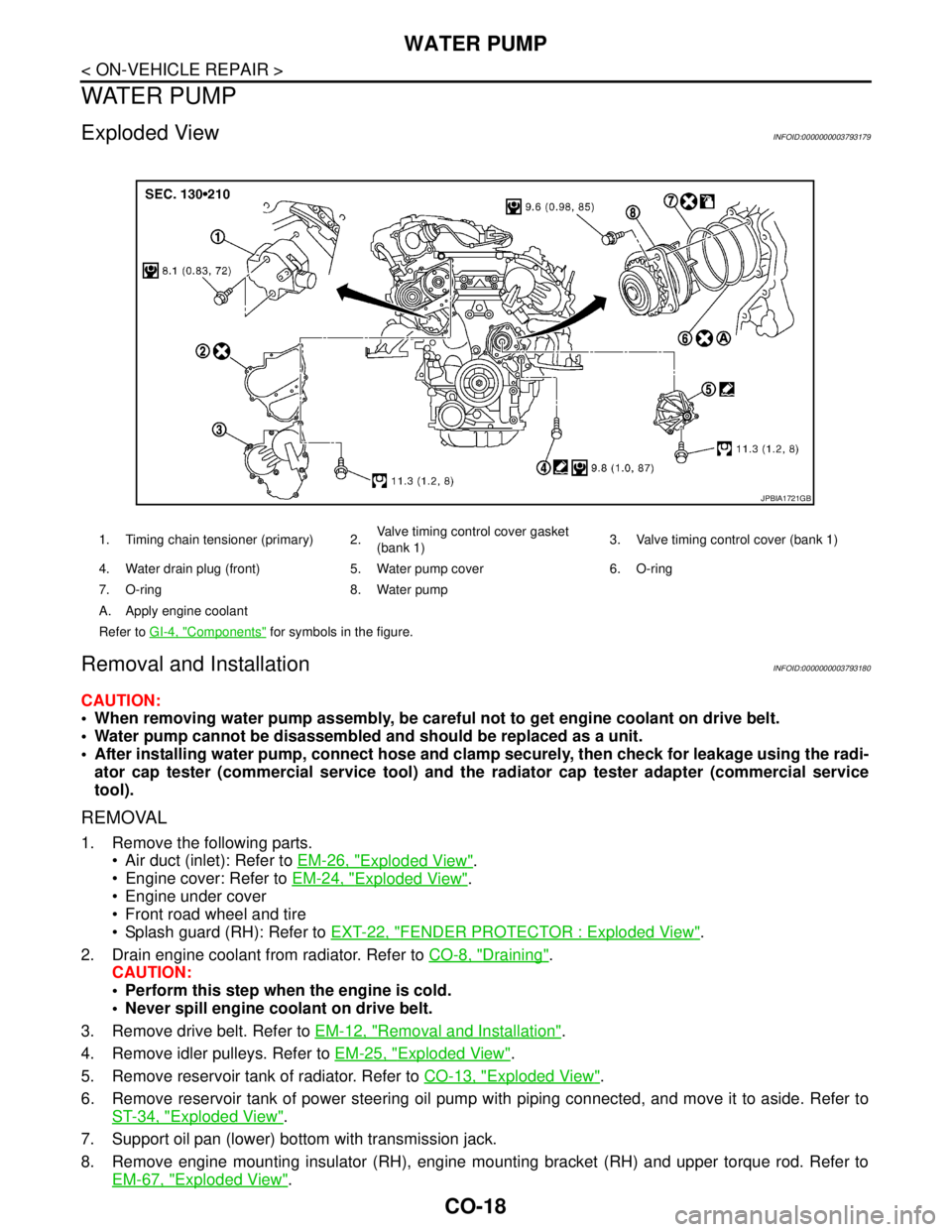
Exploded ViewINFOID:0000000003793179
Removal and InstallationINFOID:0000000003793180
CAUTION:
When removing water pump assembly, be careful not to get engine coolant on drive belt.
Water pump cannot be disassembled and should be replaced as a unit.
After installing water pump, connect hose and clamp securely, then check for leakage using the radi-
ator cap tester (commercial service tool) and the radiator cap tester adapter (commercial service
tool).
REMOVAL
1. Remove the following parts.
Air duct (inlet): Refer to EM-26, "
Exploded View".
Engine cover: Refer to EM-24, "
Exploded View".
Engine under cover
Front road wheel and tire
Splash guard (RH): Refer to EXT-22, "
FENDER PROTECTOR : Exploded View".
2. Drain engine coolant from radiator. Refer to CO-8, "
Draining".
CAUTION:
Perform this step when the engine is cold.
Never spill engine coolant on drive belt.
3. Remove drive belt. Refer to EM-12, "
Removal and Installation".
4. Remove idler pulleys. Refer to EM-25, "
Exploded View".
5. Remove reservoir tank of radiator. Refer to CO-13, "
Exploded View".
6. Remove reservoir tank of power steering oil pump with piping connected, and move it to aside. Refer to
ST-34, "
Exploded View".
7. Support oil pan (lower) bottom with transmission jack.
8. Remove engine mounting insulator (RH), engine mounting bracket (RH) and upper torque rod. Refer to
EM-67, "
Exploded View".
1. Timing chain tensioner (primary) 2.Valve timing control cover gasket
(bank 1)3. Valve timing control cover (bank 1)
4. Water drain plug (front) 5. Water pump cover 6. O-ring
7. O-ring 8. Water pump
A. Apply engine coolant
Refer to GI-4, "
Components" for symbols in the figure.
JPBIA1721GB
Page 1143 of 5121
![NISSAN TEANA 2008 Service Manual CO-20
< ON-VEHICLE REPAIR >
WATER PUMP
b. Screw M8 bolts [pitch: 1.25 mm (0.0492 in) length: approxi-
mately 50 mm (1.97 in)] into water pumps upper and lower
mounting bolt holes until they reach timi NISSAN TEANA 2008 Service Manual CO-20
< ON-VEHICLE REPAIR >
WATER PUMP
b. Screw M8 bolts [pitch: 1.25 mm (0.0492 in) length: approxi-
mately 50 mm (1.97 in)] into water pumps upper and lower
mounting bolt holes until they reach timi](/manual-img/5/57391/w960_57391-1142.png)
CO-20
< ON-VEHICLE REPAIR >
WATER PUMP
b. Screw M8 bolts [pitch: 1.25 mm (0.0492 in) length: approxi-
mately 50 mm (1.97 in)] into water pumps upper and lower
mounting bolt holes until they reach timing chain case. Then,
alternately tighten each bolt for a half turn, and pull out water
pump.
CAUTION:
Pull straight out while preventing vane from contacting
socket in installation area.
Remove water pump without causing sprocket to contact
timing chain.
c. Remove M8 bolts and O-rings from water pump.
CAUTION:
Never disassemble water pump.
INSTALLATION
1. Install new O-rings to water pump.
Apply engine oil and engine coolant to O-rings as shown in the
figure.
Locate O-ring with white paint mark to engine front side.
2. Install water pump.
CAUTION:
Never allow cylinder block to nip O-rings when installing
water pump.
Check that timing chain and water pump sprocket are
engaged.
Insert water pump by tightening mounting bolts alternately and
evenly.
3. Install timing chain tensioner (primary) as follows:
a. Turn crankshaft pulley clockwise so that timing chain on the tim-
ing chain tensioner (primary) side is loose.
JLC357B
PBIC1397E
SLC031B
PBIC4820E
Page 1148 of 5121

WATER OUTLET AND WATER PIPING
CO-25
< ON-VEHICLE REPAIR >
C
D
E
F
G
H
I
J
K
L
MA
CO
N
P O
WATER OUTLET AND WATER PIPING
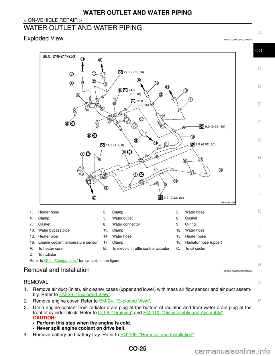
Exploded ViewINFOID:0000000003793185
Removal and InstallationINFOID:0000000003793186
REMOVAL
1. Remove air duct (inlet), air cleaner cases (upper and lower) with mass air flow sensor and air duct assem-
bly. Refer to EM-26, "
Exploded View".
2. Remove engine cover. Refer to EM-24, "
Exploded View".
3. Drain engine coolant from radiator drain plug at the bottom of radiator, and from water drain plug at the
front of cylinder block. Refer to CO-8, "
Draining" and EM-110, "Disassembly and Assembly".
CAUTION:
Perform this step when the engine is cold.
Never spill engine coolant on drive belt.
4. Remove battery and battery tray. Refer to PG-109, "
Removal and Installation".
1. Heater hose 2. Clamp 3. Water hose
4. Clamp 5. Water outlet 6. Gasket
7. Gasket 8. Water connector 9. O-ring
10. Water bypass pipe 11. Clamp 12. Water hose
13. Heater pipe 14. Water hose 15. Heater hose
16. Engine coolant temperature sensor 17. Clamp 18. Radiator hose (upper)
A. To heater core B. To electric throttle control actuator C. To oil cooler
D. To radiator
Refer to GI-4, "
Components" for symbols in the figure.
JPBIA1691GB
Page 1413 of 5121
![NISSAN TEANA 2008 Service Manual RADIATOR CORE SUPPORT
DLK-197
< ON-VEHICLE REPAIR >[WITH INTELLIGENT KEY SYSTEM]
C
D
E
F
G
H
I
J
L
MA
B
DLK
N
O
P
13. Disconnect connector of refrigerant pressure sensor. Refer to HA-50, "Exploded Vie NISSAN TEANA 2008 Service Manual RADIATOR CORE SUPPORT
DLK-197
< ON-VEHICLE REPAIR >[WITH INTELLIGENT KEY SYSTEM]
C
D
E
F
G
H
I
J
L
MA
B
DLK
N
O
P
13. Disconnect connector of refrigerant pressure sensor. Refer to HA-50, "Exploded Vie](/manual-img/5/57391/w960_57391-1412.png)
RADIATOR CORE SUPPORT
DLK-197
< ON-VEHICLE REPAIR >[WITH INTELLIGENT KEY SYSTEM]
C
D
E
F
G
H
I
J
L
MA
B
DLK
N
O
P
13. Disconnect connector of refrigerant pressure sensor. Refer to HA-50, "Exploded View".
14. Remove mounting bolt, and then remove engine coolant reservoir tank. Refer to CO-13, "
Exploded View".
15. Remove mounting bolts, and then disconnect condenser pipe assembly. Refer to HA-48, "
Exploded
View".
16. Remove condenser. Refer to HA-46, "
Removal and Installation".
17. Remove mounting nut of radiator upper hose from radiator core support, and then remove radiator upper
hose and hood switch bracket. Refer to CO-25, "
Exploded View".
18. Disconnect radiator upper hose from radiator pipe (upper). Refer to CO-25, "
Exploded View".
19. Disconnect radiator lower hose (3). Refer to CO-25, "
Exploded View".
20. Disconnect CVT fluid cooler hose on radiator side. Refer to TM-165, "
Exploded View" (CVT: RE0F09B) or
TM-329, "
Exploded View" (CVT: RE0F10A).
21. Remove power steering oil cooler pipe from radiator core sup-
port at point shown by arrows in the figure.
22. Disconnect connectors of the following parts.
Cooling fan (RH/LH). Refer to CO-16, "
Exploded View".
Crash zone sensor. Refer to SR-18, "
Removal and Installation".
23. Remove radiator upper clip. Refer to CO-13, "
Exploded View".
24. Remove all harness clips from radiator core support.
CAUTION:
Never damage radiator.
25. Support hood assembly with a proper material to prevent it from falling.
WARNING:
Bodily injury may occur if no supporting rod is holding the hood open when removing the hood
stay.
26. Remove hood support rod. Refer to DLK-195, "
HOOD SUPPORT ROD : Removal and Installation".
27. Remove mounting bolts, and then remove radiator core support.
CAUTION:
Operate with two workers, because of its heavy weight.
Never damage power steering oil cooler pipe.
28. Remove the following parts after removing radiator core support.
Radiator lower hose, radiator upper hose, radiator pipe. Refer to CO-25, "
Exploded View".
Radiator. Refer to CO-13, "
Exploded View".
Cooling fan (RH/LH). Refer to CO-16, "
Exploded View".
Crash zone sensor. Refer to SR-18, "
Exploded View".
Power steering oil cooler pipe clip. Refer to ST-34, "
Exploded View".
INSTALLATION
Install in the reverse order of removal.
JMKIA2395ZZ
: harness clip
JMKIA2396ZZ
Page 1466 of 5121

EC-5
C
D
E
F
G
H
I
J
K
L
M
ECA
N
O
P
P2122, P2123 APP SENSOR ...........................304
Description ............................................................304
DTC Logic .............................................................304
Diagnosis Procedure .............................................304
Component Inspection ..........................................306
Special Repair Requirement .................................306
P2127, P2128 APP SENSOR ...........................307
Description ............................................................307
DTC Logic .............................................................307
Diagnosis Procedure .............................................307
Component Inspection ..........................................309
Special Repair Requirement .................................310
P2135 TP SENSOR ..........................................311
Description ............................................................311
DTC Logic .............................................................311
Diagnosis Procedure .............................................311
Component Inspection ..........................................313
Special Repair Requirement .................................313
P2138 APP SENSOR .......................................314
Description ............................................................314
DTC Logic .............................................................314
Diagnosis Procedure .............................................314
Component Inspection ..........................................316
Special Repair Requirement .................................317
P2A00, P2A03 A/F SENSOR 1 ........................318
Description ............................................................318
DTC Logic .............................................................318
Diagnosis Procedure .............................................319
ASCD BRAKE SWITCH ...................................321
Description ............................................................321
Component Function Check ..................................321
Diagnosis Procedure .............................................321
Component Inspection (ASCD Brake Switch) .......322
ASCD INDICATOR ...........................................323
Description ............................................................323
Component Function Check ..................................323
Diagnosis Procedure .............................................323
COOLING FAN .................................................324
Description ............................................................324
Component Function Check ..................................324
Diagnosis Procedure .............................................324
Component Inspection (Cooling Fan Motor) .........327
Component Inspection (Cooling Fan Relay) .........328
ELECTRICAL LOAD SIGNAL .........................329
Description ............................................................329
Component Function Check ..................................329
Diagnosis Procedure .............................................329
ELECTRONIC CONTROLLED ENGINE
MOUNT .............................................................
331
Description ............................................................331
Component Function Check ..................................331
Diagnosis Procedure .............................................331
Component Inspection ...........................................332
FUEL INJECTOR ............................................334
Description .............................................................334
Component Function Check ..................................334
Diagnosis Procedure .............................................334
Component Inspection ...........................................336
FUEL PUMP ....................................................337
Description .............................................................337
Component Function Check ..................................337
Diagnosis Procedure .............................................337
Component Inspection (Fuel Pump) ......................340
Component Inspection (Condenser) ......................340
IGNITION SIGNAL ..........................................341
Description .............................................................341
Component Function Check ..................................341
Diagnosis Procedure .............................................341
Component Inspection (Ignition Coil with Power
Transistor) .............................................................
344
Component Inspection (Condenser) ......................345
MALFUNCTION INDICATOR .........................346
Description .............................................................346
Component Function Check ..................................346
Diagnosis Procedure .............................................346
POSITIVE CRANKCASE VENTILATION .......347
Description .............................................................347
Component Inspection ...........................................347
REFRIGERANT PRESSURE SENSOR ..........348
Description .............................................................348
Component Function Check ..................................348
Diagnosis Procedure .............................................348
VARIABLE INDUCTION AIR SYSTEM ..........351
Description .............................................................351
Component Function Check (VQ35DE engine) .....351
Component Function Check (VQ25DE engine) .....353
Diagnosis Procedure (VQ35DE engine) ................353
Diagnosis Procedure (VQ25DE engine) ................355
ECU DIAGNOSIS .......................................357
ECM .................................................................357
Reference Value ....................................................357
Wiring Diagram—ENGINE CONTROL SYS-
TEM— ...................................................................
371
Fail safe .................................................................386
DTC Inspection Priority Chart .............................388
DTC Index .............................................................389
How to Set SRT Code ........................................392
Test Value and Test Limit ...................................394
SYMPTOM DIAGNOSIS ............................400
ENGINE CONTROL SYSTEM SYMPTOMS ...400
Symptom Table .....................................................400
NORMAL OPERATING CONDITION .............404
Page 1481 of 5121
![NISSAN TEANA 2008 Service Manual EC-20
< FUNCTION DIAGNOSIS >[VQ25DE, VQ35DE]
ENGINE CONTROL SYSTEM
System Description
INFOID:0000000003856462
ECM performs various controls such as fuel injection control and ignition timing control.
NISSAN TEANA 2008 Service Manual EC-20
< FUNCTION DIAGNOSIS >[VQ25DE, VQ35DE]
ENGINE CONTROL SYSTEM
System Description
INFOID:0000000003856462
ECM performs various controls such as fuel injection control and ignition timing control.](/manual-img/5/57391/w960_57391-1480.png)
EC-20
< FUNCTION DIAGNOSIS >[VQ25DE, VQ35DE]
ENGINE CONTROL SYSTEM
System Description
INFOID:0000000003856462
ECM performs various controls such as fuel injection control and ignition timing control.
Component Parts LocationINFOID:0000000003856463
1. Intake valve timing control solenoid
valve (bank 1)2. Intake valve timing control solenoid
valve (bank 2)3. Electronic controlled engine mount
control solenoid valve
4. Fuel injector (bank 2) 5. Cooling fan motor-2 6. A/F sensor 1 (bank 2)
7. Ignition coil (with power transistor)
and spark plug (bank 2)8. Camshaft position sensor (PHASE)
(bank 2)9. Crankshaft position sensor (POS)
10. Engine coolant temperature sensor 11. Cooling fan motor-1 12. ECM
13. Refrigerant pressure sensor 14. Battery current sensor 15. IPDM E/R
16. Mass air flow sensor (with intake air
temperature sensor)17. Electric throttle control actuator 18. Power valve actuator 2 (VQ35DE
models)
19. EVAP canister purge volume control
solenoid valve20. Camshaft position sensor (PHASE)
(bank 1)21. Ignition coil (with power transistor)
and spark plug (bank 1)
22. A/F sensor 1 (bank 1) 23. Fuel injector (bank 1) 24. VIAS control solenoid valve 1 and 2
(VQ35DE models)
25. Power valve actuator 1
JMBIA1373ZZ
Page 1482 of 5121
![NISSAN TEANA 2008 Service Manual ENGINE CONTROL SYSTEM
EC-21
< FUNCTION DIAGNOSIS >[VQ25DE, VQ35DE]
C
D
E
F
G
H
I
J
K
L
MA
EC
N
P O
1. Mass air flow sensor (with intake air
temperature sensor)2. Electric throttle control actuator
: NISSAN TEANA 2008 Service Manual ENGINE CONTROL SYSTEM
EC-21
< FUNCTION DIAGNOSIS >[VQ25DE, VQ35DE]
C
D
E
F
G
H
I
J
K
L
MA
EC
N
P O
1. Mass air flow sensor (with intake air
temperature sensor)2. Electric throttle control actuator
:](/manual-img/5/57391/w960_57391-1481.png)
ENGINE CONTROL SYSTEM
EC-21
< FUNCTION DIAGNOSIS >[VQ25DE, VQ35DE]
C
D
E
F
G
H
I
J
K
L
MA
EC
N
P O
1. Mass air flow sensor (with intake air
temperature sensor)2. Electric throttle control actuator
: Vehicle front
1. Ignition coil (with power transistor)
and spark plug (bank 1)2. Fuel injector (bank 1) 3. Fuel injector (bank 2)
4. Ignition coil (with power transistor)
and spark plug (bank 2)5. EVAP canister
: Vehicle front
1. Knock sensor (bank 1) 2. Knock sensor (bank 2) 3. Knock sensor
: Vehicle front
JMBIA1374ZZ
JMBIA1375ZZ
JMBIA1376GB
JMBIA1377ZZ
Page 1486 of 5121
![NISSAN TEANA 2008 Service Manual ENGINE CONTROL SYSTEM
EC-25
< FUNCTION DIAGNOSIS >[VQ25DE, VQ35DE]
C
D
E
F
G
H
I
J
K
L
MA
EC
N
P O
Component DescriptionINFOID:0000000003856464
1. Fuel level sensor unit and fuel pump
harness connect NISSAN TEANA 2008 Service Manual ENGINE CONTROL SYSTEM
EC-25
< FUNCTION DIAGNOSIS >[VQ25DE, VQ35DE]
C
D
E
F
G
H
I
J
K
L
MA
EC
N
P O
Component DescriptionINFOID:0000000003856464
1. Fuel level sensor unit and fuel pump
harness connect](/manual-img/5/57391/w960_57391-1485.png)
ENGINE CONTROL SYSTEM
EC-25
< FUNCTION DIAGNOSIS >[VQ25DE, VQ35DE]
C
D
E
F
G
H
I
J
K
L
MA
EC
N
P O
Component DescriptionINFOID:0000000003856464
1. Fuel level sensor unit and fuel pump
harness connector2. Fuel pressure regulator 3. Fuel level sensor unit and fuel pump
: Vehicle front
JMBIA1385ZZ
Component Reference
A/F sensor 1EC-163, "
Description"
A/F sensor 1 heaterEC-140, "Description"
Accelerator pedal position sensorEC-304, "Description"
ASCD brake switchEC-273, "Description"
ASCD steering switchEC-270, "Description"
Battery current sensorEC-258, "Description"
Camshaft position sensor (PHASE)EC-222, "Description"
Crankshaft position sensor (POS)EC-218, "Description"
Cooling fan motorEC-324, "Description"
Electric throttle control actuatorEC-302, "Description"
Electronic controlled engine mountEC-331, "Description"
Engine coolant temperature sensorEC-157, "Description"
EVAP canister purge volume control solenoid valveEC-231, "Description"
Fuel injectorEC-334, "Description"
Fuel pumpEC-337, "Description"
Heated oxygen sensor 2EC-178, "Description"
Heated oxygen sensor 2 heaterEC-143, "Description"
Ignition coil with power transistorEC-341, "Description"
Intake air temperature sensorEC-154, "Description"
Intake valve timing control solenoid valveEC-146, "Description"
Knock sensorEC-215, "Description"
Mass air flow sensorEC-149, "Description"
PCV valveEC-347, "Description"
Power steering pressure sensorEC-236, "Description"
Power valves 1 and 2EC-351, "Description"
Refrigerant pressure sensorEC-348, "Description"
Stop lamp switchEC-291, "Description"
TCM (VQ35DE engine)
Park/neutral position (PNP) switch (VQ25DE engine)EC-245, "Description"
Throttle control motorEC-300, "Description"