2008 NISSAN TEANA cruise control
[x] Cancel search: cruise controlPage 4480 of 5121
TM-7
C
E
F
G
H
I
J
K
L
MA
B
TM
N
O
P Precaution for Supplemental Restraint System
(SRS) "AIR BAG" and "SEAT BELT PRE-TEN-
SIONER" ...............................................................
297
Precaution Necessary for Steering Wheel Rota-
tion after Battery Disconnect .................................
297
Precaution for Procedure without Cowl Top Cover ..298
Precaution for On Board Diagnosis (OBD) System
of CVT and Engine ................................................
298
Precaution for TCM and CVT Assembly Replace-
ment ......................................................................
298
Removal and Installation Procedure for CVT Unit
Connector ..............................................................
298
Precaution .............................................................299
Service Notice or Precaution .................................300
ATFTEMP COUNT Conversion Table ..................301
PREPARATION .........................................302
PREPARATION ................................................302
Special Service Tools ............................................302
Commercial Service Tools ....................................302
ON-VEHICLE MAINTENANCE ..................304
CVT FLUID .......................................................304
Inspection ..............................................................304
Changing ...............................................................305
STALL TEST ....................................................306
Inspection and Judgment ......................................306
LINE PRESSURE TEST ...................................308
Inspection and Judgment ......................................308
ROAD TEST .....................................................310
Description ............................................................310
Check before Engine Is Started ............................310
Check at Idle .........................................................311
Cruise Test ............................................................312
CVT POSITION .................................................314
Inspection and Adjustment ....................................314
ON-VEHICLE REPAIR ...............................315
TRANSMISSION CONTROL MODULE ...........315
Exploded View ......................................................315
Removal and Installation .......................................315
CONTROL DEVICE ..........................................317
Exploded View ......................................................317
Removal and Installation .......................................317
Inspection and Adjustment ....................................318
CONTROL CABLE ...........................................319
Exploded View ......................................................319
Removal and Installation .......................................319
Inspection and Adjustment ....................................320
OIL PAN ...........................................................321
Exploded View ......................................................321
Removal and Installation .......................................321
Inspection ..............................................................322
PRIMARY SPEED SENSOR ...........................323
Exploded View .......................................................323
Removal and Installation .......................................323
Inspection ..............................................................323
SECONDARY SPEED SENSOR ....................324
Exploded View .......................................................324
Removal and Installation .......................................324
Inspection ..............................................................324
DIFFERENTIAL SIDE OIL SEAL ....................325
Exploded View .......................................................325
Removal and Installation .......................................325
Inspection ..............................................................326
OIL PUMP FITTING BOLT ..............................327
Description .............................................................327
Exploded View .......................................................327
Removal and Installation .......................................327
Inspection ..............................................................327
AIR BREATHER HOSE ..................................328
Exploded View .......................................................328
Removal and Installation .......................................328
FLUID COOLER SYSTEM ..............................329
Exploded View .......................................................329
Removal and Installation .......................................329
Inspection ..............................................................331
REMOVAL AND INSTALLATION .............332
TRANSAXLE ASSEMBLY ..............................332
Exploded View .......................................................332
Removal and Installation .......................................332
Inspection ..............................................................334
DISASSEMBLY AND ASSEMBLY ............335
TORQUE CONVERTER AND CONVERTER
HOUSING OIL SEAL ......................................
335
Exploded View .......................................................335
Disassembly ..........................................................335
Assembly ...............................................................335
Inspection ..............................................................336
SERVICE DATA AND SPECIFICATIONS
(SDS) ..........................................................
337
SERVICE DATA AND SPECIFICATIONS
(SDS) ...............................................................
337
General Specification ............................................337
Vehicle Speed When Shifting Gears .....................337
Stall Speed ............................................................337
Line Pressure ........................................................337
Solenoid Valves .....................................................338
CVT Fluid Temperature Sensor .............................338
Primary Speed Sensor ..........................................338
Secondary Speed Sensor ......................................338
Page 4943 of 5121

WCS
DIAGNOSIS SYSTEM (METER)
WCS-13
< FUNCTION DIAGNOSIS >
C
D
E
F
G
H
I
J
K
L
MB A
O
P
W TEMP METER
[°C] XValue of engine coolant temperature signal is received from ECM via CAN com-
munication.
NOTE:
215 is displayed when the malfunction signal is input.
ABS W/L
[On/Off]Status of ABS warning lamp detected from ABS warning lamp signal is received
from ABS actuator and electric unit (control unit) via CAN communication.
VDC/TCS IND
[On/Off]Status of VDC OFF indicator lamp detected from VDC OFF indicator lamp signal
is received from ABS actuator and electric unit (control unit) via CAN communica-
tion.
SLIP IND
[On/Off]Status of SLIP indicator lamp detected from slip indicator lamp signal received
from ABS actuator and electric unit (control unit) via CAN communication.
BRAKE W/L
[On/Off]Status of brake warning lamp detected from brake warning lamp signal is received
from ABS actuator and electric unit (control unit) via CAN communication.
NOTE:
Displays “Off” if the brake warning lamp is illuminated when the valve check starts,
the parking brake switch is turned ON or the brake fluid level switch is turned ON.
DOOR W/L
[On/Off]Status of door warning detected from door switch signal received from BCM via
CAN communication.
TRUNK/GLAS-H
[On/Off]Status of trunk warning detected from trunk switch signal received from BCM via
CAN communication.
HI-BEAM IND
[On/Off]Status of high beam indicator lamp detected from high beam request signal is re-
ceived from BCM via CAN communication.
TURN IND
[On/Off]Status of turn indicator lamp detected from turn indicator signal is received from
BCM via CAN communication.
FR FOG IND
[On/Off]Status of front fog light indicator lamp detected from front fog light request signal
is received from BCM via CAN communication.
RR FOG IND
[On/Off]Status of rear fog light indicator lamp detected from rear fog light request signal is
received from BCM via CAN communication.
LIGHT IND
[On/Off]Status of light indicator lamp detected from position light request signal is received
from BCM via CAN communication.
OIL W/L
[On/Off]Status of oil pressure warning lamp detected from oil pressure switch signal is re-
ceived from BCM via CAN communication.
MIL
[On/Off] Status of malfunction indicator lamp detected from malfunctioning indicator lamp
signal is received from ECM via CAN communication.
CRUISE IND
[On/Off]Status of CRUISE indicator detected from ASCD status signal is received from
ECM via CAN communication.
SPORT IND
[On/Off]Status of SPORT indicator detected from sport mode switch signal is received
from control device.
4WD W/L
[On/Off]This item is displayed, but cannot be monitored.
4WD LOCK IND
[On/Off]This item is displayed, but cannot be monitored.
FUEL W/L
[On/Off]Low-fuel warning lamp status detected by the identified fuel level.
WASHER W/L
[On/Off]This item is displayed, but cannot be monitored.
KEY G/Y W/L
[On/Off]Status of key warning lamp (G/Y) detected from key warning signal is received
from BCM via CAN communication.
AFS OFF IND
[On/Off]This item is displayed, but cannot be monitored.
LCD
[B&P N, B&P I, ID NG, ROTAT, SFT
P, INSRT, BATT, NO KY,OUTKY, LK
WN]Displays status of Intelligent Key system warning detected from meter display sig-
nal is received from BCM via CAN communication.
Display item [Unit]MAIN
SIGNALSDescription
Page 4970 of 5121
WCS-40
< ECU DIAGNOSIS >
COMBINATION METER
DTC Index
INFOID:0000000003838733
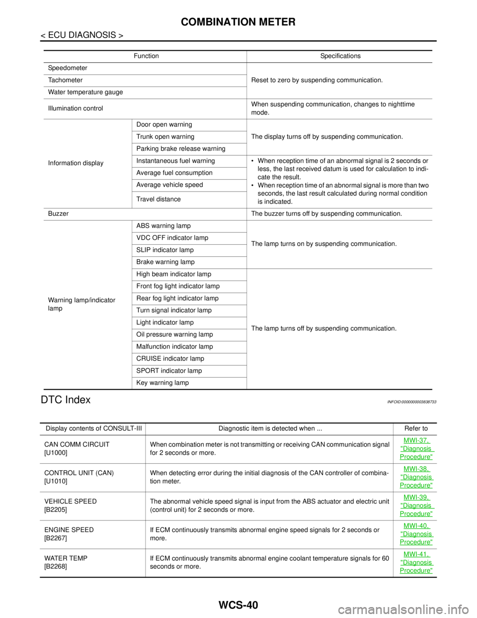
Function Specifications
Speedometer
Reset to zero by suspending communication. Tachometer
Water temperature gauge
Illumination controlWhen suspending communication, changes to nighttime
mode.
Information displayDoor open warning
The display turns off by suspending communication. Trunk open warning
Parking brake release warning
Instantaneous fuel warning When reception time of an abnormal signal is 2 seconds or
less, the last received datum is used for calculation to indi-
cate the result.
When reception time of an abnormal signal is more than two
seconds, the last result calculated during normal condition
is indicated. Average fuel consumption
Average vehicle speed
Travel distance
Buzzer The buzzer turns off by suspending communication.
Warning lamp/indicator
lampABS warning lamp
The lamp turns on by suspending communication. VDC OFF indicator lamp
SLIP indicator lamp
Brake warning lamp
High beam indicator lamp
The lamp turns off by suspending communication. Front fog light indicator lamp
Rear fog light indicator lamp
Turn signal indicator lamp
Light indicator lamp
Oil pressure warning lamp
Malfunction indicator lamp
CRUISE indicator lamp
SPORT indicator lamp
Key warning lamp
Display contents of CONSULT-III Diagnostic item is detected when ... Refer to
CAN COMM CIRCUIT
[U1000]When combination meter is not transmitting or receiving CAN communication signal
for 2 seconds or more.MWI-37,
"Diagnosis
Procedure"
CONTROL UNIT (CAN)
[U1010]When detecting error during the initial diagnosis of the CAN controller of combina-
tion meter.MWI-38, "Diagnosis
Procedure"
VEHICLE SPEED
[B2205]The abnormal vehicle speed signal is input from the ABS actuator and electric unit
(control unit) for 2 seconds or more.MWI-39, "Diagnosis
Procedure"
ENGINE SPEED
[B2267]If ECM continuously transmits abnormal engine speed signals for 2 seconds or
more.MWI-40, "Diagnosis
Procedure"
WATER TEMP
[B2268]If ECM continuously transmits abnormal engine coolant temperature signals for 60
seconds or more.MWI-41, "Diagnosis
Procedure"