2008 NISSAN TEANA ECU
[x] Cancel search: ECUPage 5014 of 5121
WW-2
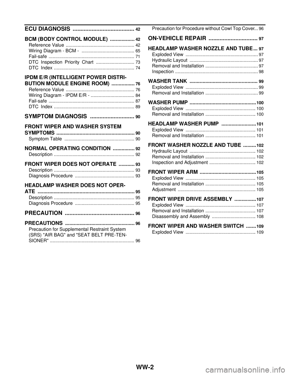
ECU DIAGNOSIS ........................................42
BCM (BODY CONTROL MODULE) ..................42
Reference Value .....................................................42
Wiring Diagram - BCM - .........................................65
Fail-safe ..................................................................71
DTC Inspection Priority Chart ..............................73
DTC Index ..............................................................74
IPDM E/R (INTELLIGENT POWER DISTRI-
BUTION MODULE ENGINE ROOM) .................
76
Reference Value .....................................................76
Wiring Diagram - IPDM E/R - ..................................84
Fail-safe ..................................................................87
DTC Index ..............................................................89
SYMPTOM DIAGNOSIS .............................90
FRONT WIPER AND WASHER SYSTEM
SYMPTOMS .......................................................
90
Symptom Table ......................................................90
NORMAL OPERATING CONDITION ................92
Description ..............................................................92
FRONT WIPER DOES NOT OPERATE ............93
Description ..............................................................93
Diagnosis Procedure ..............................................93
HEADLAMP WASHER DOES NOT OPER-
ATE ....................................................................
95
Description ..............................................................95
Diagnosis Procedure ..............................................95
PRECAUTION .............................................96
PRECAUTIONS .................................................96
Precaution for Supplemental Restraint System
(SRS) "AIR BAG" and "SEAT BELT PRE-TEN-
SIONER" .................................................................
96
Precaution for Procedure without Cowl Top Cover ...96
ON-VEHICLE REPAIR ...............................97
HEADLAMP WASHER NOZZLE AND TUBE ...97
Exploded View ........................................................97
Hydraulic Layout .....................................................97
Removal and Installation .........................................97
Inspection ................................................................98
WASHER TANK ................................................99
Exploded View ........................................................99
Removal and Installation .........................................99
WASHER PUMP ...............................................100
Exploded View ......................................................100
Removal and Installation .......................................100
HEADLAMP WASHER PUMP .........................101
Exploded View ......................................................101
Removal and Installation .......................................101
FRONT WASHER NOZZLE AND TUBE ..........102
Hydraulic Layout ...................................................102
Removal and Installation .......................................102
Inspection and Adjustment ....................................102
FRONT WIPER ARM ........................................105
Exploded View ......................................................105
Removal and Installation .......................................105
Adjustment ............................................................105
FRONT WIPER DRIVE ASSEMBLY ................107
Exploded View ......................................................107
Removal and Installation .......................................107
Disassembly and Assembly ..................................108
FRONT WIPER AND WASHER SWITCH ........109
Exploded View ......................................................109
Page 5024 of 5121
WW-12
< FUNCTION DIAGNOSIS >
DIAGNOSIS SYSTEM (BCM)
DIAGNOSIS SYSTEM (BCM)
COMMON ITEM
COMMON ITEM : CONSULT-III Function (BCM - COMMON ITEM)INFOID:0000000003941291
APPLICATION ITEM
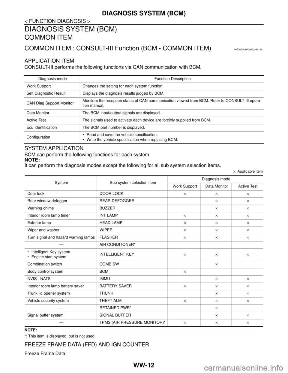
CONSULT-III performs the following functions via CAN communication with BCM.
SYSTEM APPLICATION
BCM can perform the following functions for each system.
NOTE:
It can perform the diagnosis modes except the following for all sub system selection items.
×: Applicable item
NOTE:
*: This item is displayed, but is not used.
FREEZE FRAME DATA (FFD) AND IGN COUNTER
Freeze Frame Data
Diagnosis mode Function Description
Work Support Changes the setting for each system function.
Self Diagnostic Result Displays the diagnosis results judged by BCM.
CAN Diag Support MonitorMonitors the reception status of CAN communication viewed from BCM. Refer to CONSULT-III opera-
tion manual.
Data Monitor The BCM input/output signals are displayed.
Active Test The signals used to activate each device are forcibly supplied from BCM.
Ecu Identification The BCM part number is displayed.
Configuration Read and save the vehicle specification.
Write the vehicle specification when replacing BCM.
System Sub system selection itemDiagnosis mode
Work Support Data Monitor Active Test
Door lock DOOR LOCK×××
Rear window defogger REAR DEFOGGER××
Warning chime BUZZER××
Interior room lamp timer INT LAMP×××
Exterior lamp HEAD LAMP×××
Wiper and washer WIPER×××
Turn signal and hazard warning lamps FLASHER×××
— AIR CONDITONER*
Intelligent Key system
Engine start systemINTELLIGENT KEY×××
Combination switch COMB SW×
Body control system BCM×
NVIS - NATS IMMU××
Interior room lamp battery saver BATTERY SAVER×××
Trunk lid opener system TRUNK××
Vehicle security system THEFT ALM×××
— RETAINED PWR*×
Signal buffer system SIGNAL BUFFER××
— TPMS (AIR PRESSURE MONITOR)*×××
Page 5029 of 5121

DIAGNOSIS SYSTEM (IPDM E/R)
WW-17
< FUNCTION DIAGNOSIS >
C
D
E
F
G
H
I
J
K
MA
B
WW
N
O
P
CONSULT-III Function (IPDM E/R)INFOID:0000000003941293
APPLICATION ITEM
CONSULT-III performs the following functions via CAN communication with IPDM E/R.
SELF DIAGNOSTIC RESULT
Refer to WW-89, "DTCIndex".
DATA MONITOR
Monitor item
Cooling fan does not operatePerform auto active test.
Does the cooling fan operate?YES ECM signal input circuit
CAN communication signal
between ECM and IPDM E/
R
NO Harness or connector be-
tween IPDM E/R and cool-
ing fan motor
Harness or connector be-
tween IPDM E/R and cool-
ing fan relay
Cooling fan motor
Cooling fan relay
IPDM E/R Symptom Inspection contents Possible cause
Diagnosis mode Description
Ecu Identification Allows confirmation of IPDM E/R part number.
Self Diagnostic Result Displays the diagnosis results judged by IPDM E/R.
Data Monitor Displays the real-time input/output data from IPDM E/R input/output data.
Active Test IPDM E/R can provide a drive signal to electronic components to check their operations.
CAN Diag Support Monitor The results of transmit/receive diagnosis of CAN communication can be read.
Monitor Item
[Unit]MAIN SIG-
NALSDescription
MOTOR FAN REQ
[1/2/3/4]×Displays the value of the cooling fan speed request signal received from ECM via
CAN communication.
AC COMP REQ
[Off/On]×Displays the status of the A/C compressor request signal received from ECM via
CAN communication.
TAIL&CLR REQ
[Off/On]×Displays the status of the position light request signal received from BCM via CAN
communication.
HL LO REQ
[Off/On]×Displays the status of the low beam request signal received from BCM via CAN
communication.
HL HI REQ
[Off/On]×Displays the status of the high beam request signal received from BCM via CAN
communication.
FR FOG REQ
[Off/On]×Displays the status of the front fog light request signal received from BCM via
CAN communication.
FR WIP REQ
[Stop/1LOW/Low/Hi]×Displays the status of the front wiper request signal received from BCM via CAN
communication.
WIP AUTO STOP
[STOP P/ACT P]×Displays the status of the front wiper auto stop signal judged by IPDM E/R.
WIP PROT
[Off/BLOCK]×Displays the status of the front wiper fail-safe operation judged by IPDM E/R.
IGN RLY1 -REQ
[Off/On]Displays the status of the ignition switch ON signal received from BCM via CAN
communication.
Page 5054 of 5121
WW-42
< ECU DIAGNOSIS >
BCM (BODY CONTROL MODULE)
ECU DIAGNOSIS
BCM (BODY CONTROL MODULE)
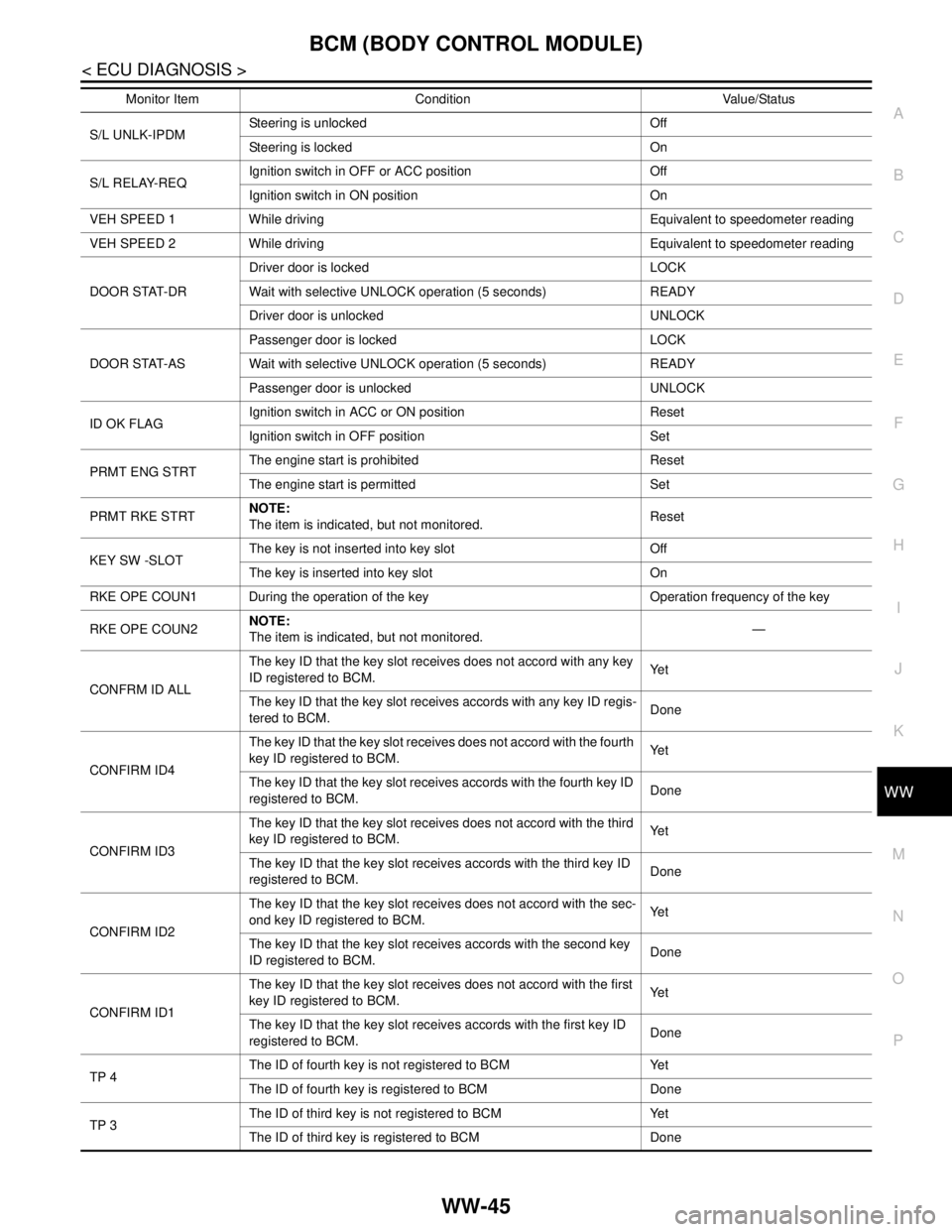
Reference ValueINFOID:0000000003941296
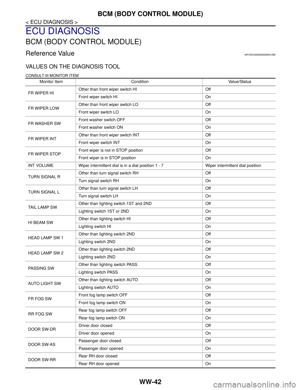
VALUES ON THE DIAGNOSIS TOOL
CONSULT-III MONITOR ITEM
Monitor Item Condition Value/Status
FR WIPER HIOther than front wiper switch HI Off
Front wiper switch HI On
FR WIPER LOWOther than front wiper switch LO Off
Front wiper switch LO On
FR WASHER SWFront washer switch OFF Off
Front washer switch ON On
FR WIPER INTOther than front wiper switch INT Off
Front wiper switch INT On
FR WIPER STOPFront wiper is not in STOP position Off
Front wiper is in STOP position On
INT VOLUME Wiper intermittent dial is in a dial position 1 - 7 Wiper intermittent dial position
TURN SIGNAL ROther than turn signal switch RH Off
Turn signal switch RH On
TURN SIGNAL LOther than turn signal switch LH Off
Turn signal switch LH On
TAIL LAMP SWOther than lighting switch 1ST and 2ND Off
Lighting switch 1ST or 2ND On
HI BEAM SWOther than lighting switch HI Off
Lighting switch HI On
HEAD LAMP SW 1Other than lighting switch 2ND Off
Lighting switch 2ND On
HEAD LAMP SW 2Other than lighting switch 2ND Off
Lighting switch 2ND On
PASSING SWOther than lighting switch PASS Off
Lighting switch PASS On
AUTO LIGHT SWOther than lighting switch AUTO Off
Lighting switch AUTO On
FR FOG SWFront fog lamp switch OFF Off
Front fog lamp switch ON On
RR FOG SWRear fog lamp switch OFF Off
Rear fog lamp switch ON On
DOOR SW-DRDriver door closed Off
Driver door opened On
DOOR SW-ASPassenger door closed Off
Passenger door opened On
DOOR SW-RRRear RH door closed Off
Rear RH door opened On
Page 5055 of 5121

BCM (BODY CONTROL MODULE)
WW-43
< ECU DIAGNOSIS >
C
D
E
F
G
H
I
J
K
MA
B
WW
N
O
P
DOOR SW-RLRear LH door closed Off
Rear LH door opened On
DOOR SW-BKNOTE:
The item is indicated, but not monitored. Off
CDL LOCK SWOther than power door lock switch LOCK Off
Power door lock switch LOCK On
CDL UNLOCK SWOther than power door lock switch UNLOCK Off
Power door lock switch UNLOCK On
KEY CYL LK-SWNOTE:
The item is indicated, but not monitored. Off
KEY CYL UN-SWNOTE:
The item is indicated, but not monitored. Off
KEY CYL SW-TRNOTE:
The item is indicated, but not monitored. Off
HAZARD SWHazard switch is OFF Off
Hazard switch is ON On
REAR DEF SW
NOTE:
At model with BOSE au-
dio system this item is in-
dicated, but is not
monitored.Rear window defogger switch is OFF Off
Rear window defogger switch is ON On
TR CANCEL SWNOTE:
The item is indicated, but not monitored. Off
TR/BD OPEN SWTrunk lid opener switch OFF Off
While the trunk lid opener switch is turned ON On
TRNK/HAT MNTRTrunk lid closed Off
Trunk lid opened On
RKE-LOCKLOCK button of the key is not pressed Off
LOCK button of the key is pressed On
RKE-UNLOCKUNLOCK button of the key is not pressed Off
UNLOCK button of the key is pressed On
RKE-TR/BDTRUNK OPEN button of the key is not pressed Off
TRUNK OPEN button of the key is pressed On
RKE-PANICNOTE:
The item is indicated, but not monitored. Off
RKE-P/W OPENNOTE:
The item is indicated, but not monitored. Off
RKE-MODE CHGLOCK/UNLOCK button of the key is not pressed and held simulta-
neouslyOff
LOCK/UNLOCK button of the key is pressed and held simulta-
neouslyOn
OPTICAL SENSORBright outside of the vehicle Close to 5 V
Dark outside of the vehicle Close to 0 V
REQ SW -DRDriver door request switch is not pressed Off
Driver door request switch is pressed On
REQ SW -ASPassenger door request switch is not pressed Off
Passenger door request switch is pressed On Monitor Item Condition Value/Status
Page 5056 of 5121
WW-44
< ECU DIAGNOSIS >
BCM (BODY CONTROL MODULE)
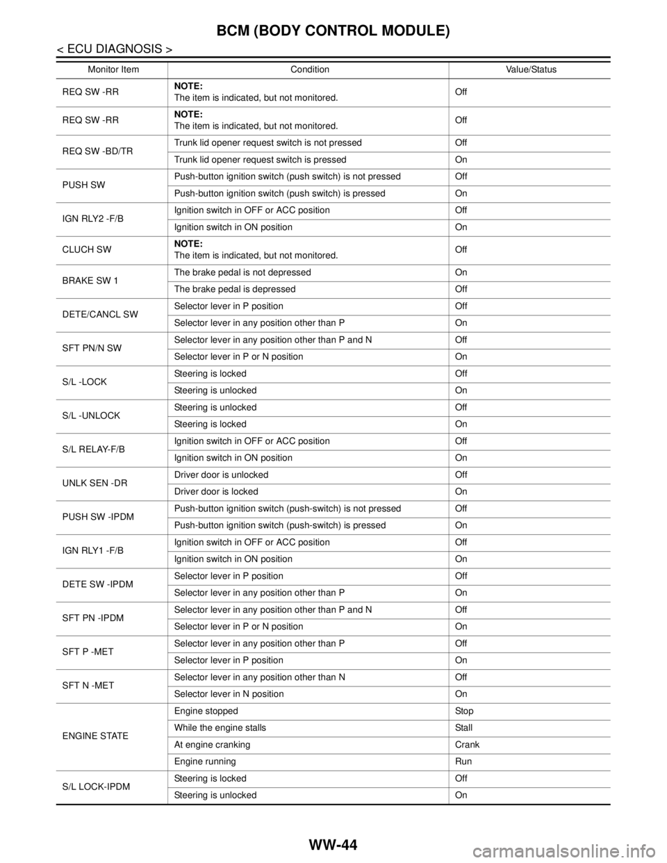
REQ SW -RRNOTE:
The item is indicated, but not monitored. Off
REQ SW -RRNOTE:
The item is indicated, but not monitored. Off
REQ SW -BD/TRTrunk lid opener request switch is not pressed Off
Trunk lid opener request switch is pressed On
PUSH SWPush-button ignition switch (push switch) is not pressed Off
Push-button ignition switch (push switch) is pressed On
IGN RLY2 -F/BIgnition switch in OFF or ACC position Off
Ignition switch in ON position On
CLUCH SWNOTE:
The item is indicated, but not monitored. Off
BRAKE SW 1The brake pedal is not depressed On
The brake pedal is depressed Off
DETE/CANCL SWSelector lever in P position Off
Selector lever in any position other than P On
SFT PN/N SWSelector lever in any position other than P and N Off
Selector lever in P or N position On
S/L -LOCKSteering is locked Off
Steering is unlocked On
S/L -UNLOCKSteering is unlocked Off
Steering is locked On
S/L RELAY-F/BIgnition switch in OFF or ACC position Off
Ignition switch in ON position On
UNLK SEN -DRDriver door is unlocked Off
Driver door is locked On
PUSH SW -IPDMPush-button ignition switch (push-switch) is not pressed Off
Push-button ignition switch (push-switch) is pressed On
IGN RLY1 -F/BIgnition switch in OFF or ACC position Off
Ignition switch in ON position On
DETE SW -IPDMSelector lever in P position Off
Selector lever in any position other than P On
SFT PN -IPDMSelector lever in any position other than P and N Off
Selector lever in P or N position On
SFT P -METSelector lever in any position other than P Off
Selector lever in P position On
SFT N -METSelector lever in any position other than N Off
Selector lever in N position On
ENGINE STATEEngine stopped Stop
While the engine stalls Stall
At engine cranking Crank
Engine running Run
S/L LOCK-IPDMSteering is locked Off
Steering is unlocked On Monitor Item Condition Value/Status
Page 5057 of 5121
BCM (BODY CONTROL MODULE)
WW-45
< ECU DIAGNOSIS >
C
D
E
F
G
H
I
J
K
MA
B
WW
N
O
P
S/L UNLK-IPDMSteering is unlocked Off
Steering is locked On
S/L RELAY-REQIgnition switch in OFF or ACC position Off
Ignition switch in ON position On
VEH SPEED 1 While driving Equivalent to speedometer reading
VEH SPEED 2 While driving Equivalent to speedometer reading
DOOR STAT-DRDriver door is locked LOCK
Wait with selective UNLOCK operation (5 seconds) READY
Driver door is unlocked UNLOCK
DOOR STAT-ASPassenger door is locked LOCK
Wait with selective UNLOCK operation (5 seconds) READY
Passenger door is unlocked UNLOCK
ID OK FLAGIgnition switch in ACC or ON position Reset
Ignition switch in OFF position Set
PRMT ENG STRTThe engine start is prohibited Reset
The engine start is permitted Set
PRMT RKE STRTNOTE:
The item is indicated, but not monitored. Reset
KEY SW -SLOTThe key is not inserted into key slot Off
The key is inserted into key slot On
RKE OPE COUN1 During the operation of the key Operation frequency of the key
RKE OPE COUN2NOTE:
The item is indicated, but not monitored. —
CONFRM ID ALLThe key ID that the key slot receives does not accord with any key
ID registered to BCM.Ye t
The key ID that the key slot receives accords with any key ID regis-
tered to BCM.Done
CONFIRM ID4The key ID that the key slot receives does not accord with the fourth
key ID registered to BCM.Ye t
The key ID that the key slot receives accords with the fourth key ID
registered to BCM.Done
CONFIRM ID3The key ID that the key slot receives does not accord with the third
key ID registered to BCM.Ye t
The key ID that the key slot receives accords with the third key ID
registered to BCM.Done
CONFIRM ID2The key ID that the key slot receives does not accord with the sec-
ond key ID registered to BCM.Ye t
The key ID that the key slot receives accords with the second key
ID registered to BCM.Done
CONFIRM ID1The key ID that the key slot receives does not accord with the first
key ID registered to BCM.Ye t
The key ID that the key slot receives accords with the first key ID
registered to BCM.Done
TP 4The ID of fourth key is not registered to BCM Yet
The ID of fourth key is registered to BCM Done
TP 3The ID of third key is not registered to BCM Yet
The ID of third key is registered to BCM Done Monitor Item Condition Value/Status
Page 5058 of 5121

WW-46
< ECU DIAGNOSIS >
BCM (BODY CONTROL MODULE)
TERMINAL LAYOUT
TP 2The ID of second key is not registered to BCM Yet
The ID of second key is registered to BCM Done
TP 1The ID of first key is not registered to BCM Yet
The ID of first key is registered to BCM Done Monitor Item Condition Value/Status
JPMIA0062ZZ