2008 NISSAN TEANA coolant
[x] Cancel search: coolantPage 2859 of 5121
![NISSAN TEANA 2008 Service Manual INSUFFICIENT HEATING
HAC-231
< SYMPTOM DIAGNOSIS >[WITH 7 INCH DISPLAY]
C
D
E
F
G
H
J
K
L
MA
B
HAC
N
O
P
INSUFFICIENT HEATING
DescriptionINFOID:0000000003884803
Symptom
Insufficient heating
No war NISSAN TEANA 2008 Service Manual INSUFFICIENT HEATING
HAC-231
< SYMPTOM DIAGNOSIS >[WITH 7 INCH DISPLAY]
C
D
E
F
G
H
J
K
L
MA
B
HAC
N
O
P
INSUFFICIENT HEATING
DescriptionINFOID:0000000003884803
Symptom
Insufficient heating
No war](/manual-img/5/57391/w960_57391-2858.png)
INSUFFICIENT HEATING
HAC-231
< SYMPTOM DIAGNOSIS >[WITH 7 INCH DISPLAY]
C
D
E
F
G
H
J
K
L
MA
B
HAC
N
O
P
INSUFFICIENT HEATING
DescriptionINFOID:0000000003884803
Symptom
Insufficient heating
No warm air comes out. (Air flow volume is normal.)
Inspection procedureINFOID:0000000003884804
1.CHECK COOLING SYSTEM
1. Check engine coolant level and check for leakage. Refer to CO-8, "
Inspection".
2. Check radiator cap. Refer to CO-12, "
RADIATOR CAP : Inspection".
3. Check water flow sounds of engine coolant. Refer to CO-9, "
Refilling".
Is the inspection result normal?
YES >> GO TO 2.
NO >> Refill the engine coolant and repair or replace the parts according to the inspection results.
2.CHECK OPERATION
1. Press temperature control dial (driver side) and raise temperature setting to 32°C (90°F) after warming up
the engine.
2. Check that warm air blows from the outlets.
Is the inspection result normal?
YES >> END.
NO >> GO TO 3.
3.CHECK SETTING OF TEMPERATURE SETTING TRIMMER
Using CONSULT-III, check the setting of “TEMP SET CORRECT” on “WORK SUPPORT” of HVAC. Refer to
HAC-110, "
WITHOUT INTELLIGENT AIR CONDITIONER SYSTEM : Temperature Setting Trimmer" (WITH-
OUT INTELLIGENT AIR CONDITIONER SYSTEM) or HAC-114, "
WITH INTELLIGENT AIR CONDITIONER
SYSTEM : Temperature Setting Trimmer" (WITH INTELLIGENT AIR CONDITIONER SYSTEM).
1. Check that the temperature setting trimmer is set to “− direction”.
NOTE:
The control temperature can be set by the temperature setting trimmer.
2. Set temperature control dial to “0”.
Are the malfunction solved?
YES >> Perform the setting separately if necessary. END.
NO >> GO TO 4.
4.CHECK WITH SELF-DIAGNOSIS FUNCTION OF CONSULT-III
1. Using CONSULT-III, perform “SELF-DIAGNOSIS RESULTS” of HVAC.
2. Check if any DTC is displayed in the trouble diagnosis results.
NOTE:
If DTC is displayed along with DTC U1000 or U1010, first diagnose the DTC U1000 or U1010. Refer to
HAC-164, "
DTC Logic" or HAC-165, "DTC Logic".
Is any DTC displayed?
YES >> Perform the diagnosis that is applicable to the sensor and the door motor. Refer to HAC-212,
"WITHOUT INTELLIGENT AIR CONDITIONER SYSTEM : DTC Index" (WITHOUT INTELLI-
GENT AIR CONDITIONER SYSTEM) or HAC-224, "
WITH INTELLIGENT AIR CONDITIONER
SYSTEM : DTC Index" (WITH INTELLIGENT AIR CONDITIONER SYSTEM).
NO >> GO TO 5.
5.CHECK WITH ACTIVE TEST OF CONSULT-III
1. Using CONSULT-III, perform “HVAC TEST” in “ACTIVE TEST” of HVAC to check each output device.
Refer to HAC-156, "
WITHOUT INTELLIGENT AIR CONDITIONER SYSTEM : CONSULT-III Function"
(WITHOUT INTELLIGENT AIR CONDITIONER SYSTEM) or HAC-159, "WITH INTELLIGENT AIR CON-
DITIONER SYSTEM : CONSULT-III Function" (WITH INTELLIGENT AIR CONDITIONER SYSTEM).
NOTE:
Page 2861 of 5121
![NISSAN TEANA 2008 Service Manual INSUFFICIENT HEATING
HAC-233
< SYMPTOM DIAGNOSIS >[WITH 7 INCH DISPLAY]
C
D
E
F
G
H
J
K
L
MA
B
HAC
N
O
P
YES >> GO TO 8.
NO >> Repair or replace parts according to the inspection results.
8.CHECK TEMP NISSAN TEANA 2008 Service Manual INSUFFICIENT HEATING
HAC-233
< SYMPTOM DIAGNOSIS >[WITH 7 INCH DISPLAY]
C
D
E
F
G
H
J
K
L
MA
B
HAC
N
O
P
YES >> GO TO 8.
NO >> Repair or replace parts according to the inspection results.
8.CHECK TEMP](/manual-img/5/57391/w960_57391-2860.png)
INSUFFICIENT HEATING
HAC-233
< SYMPTOM DIAGNOSIS >[WITH 7 INCH DISPLAY]
C
D
E
F
G
H
J
K
L
MA
B
HAC
N
O
P
YES >> GO TO 8.
NO >> Repair or replace parts according to the inspection results.
8.CHECK TEMPERATURE OF HEATER HOSE
1. Check the temperature of inlet hose and outlet hose of heater core.
2. Check that the inlet side of heater core is hot and the outlet side is slightly lower than/almost equal to the
inlet side.
CAUTION:
Always perform the temperature inspection in a short period of time because the engine coolant
temperature is very hot.
Is the inspection result normal?
YES >> GO TO 9.
NO >> Replace the heater core after performing the procedures after the cooling system inspection. GO
TO 1.
9.REPLACE HEATER CORE
Replace the heater core. Refer to heater core. Refer to VTL-101, "
Exploded View".
Are the malfunction solved?
YES >> END.
NO >> Perform the procedures again after the cooling system inspection. GO TO 1.
Page 3090 of 5121
![NISSAN TEANA 2008 Service Manual LAN
CAN COMMUNICATION SYSTEM
LAN-23
< FUNCTION DIAGNOSIS >[CAN]
C
D
E
F
G
H
I
J
K
L B A
O
P N
NOTE:
Refer to LAN-19, "
Abbreviation List" for the abbreviations of the connecting units.
T: Transmit R: NISSAN TEANA 2008 Service Manual LAN
CAN COMMUNICATION SYSTEM
LAN-23
< FUNCTION DIAGNOSIS >[CAN]
C
D
E
F
G
H
I
J
K
L B A
O
P N
NOTE:
Refer to LAN-19, "
Abbreviation List" for the abbreviations of the connecting units.
T: Transmit R:](/manual-img/5/57391/w960_57391-3089.png)
LAN
CAN COMMUNICATION SYSTEM
LAN-23
< FUNCTION DIAGNOSIS >[CAN]
C
D
E
F
G
H
I
J
K
L B A
O
P N
NOTE:
Refer to LAN-19, "
Abbreviation List" for the abbreviations of the connecting units.
T: Transmit R: Receive
Signal name/Connecting unitECM
ADP
AV
HVAC
M&A
STRG
BCM
ABS
TCM
IPDM-E
A/C compressor request signal TR
Accelerator pedal position signal T R R
ASCD CRUISE indicator signal T R
ASCD operation signal T R
ASCD SET indicator signal T R
Closed throttle position signal T R
Cooling fan speed request signal TR
Engine and CVT integrated control signalTR
RT
Engine coolant temperature signal T R
Engine speed signal T R R R
Engine status signal T R R
Fuel consumption monitor signal T R
Malfunctioning indicator lamp signal T R
Power generation command value signal TR
System setting signalTR
RT R
RT
Rear window defogger switch signal T R
A/C switch signal R T T
Blower fan motor switch signal R T T
Distance to empty signal R T
Fuel level low warning signal R T
Sleep-ready signalTR
RT
Sport mode switch signal T R
Vehicle speed signalRR T R RR
RR R R T
Wake up signal T R
Steering angle sensor signal T R
Buzzer output signal R T
Door switch signal R R R T R
Door unlock signal R T
Front fog light request signal R T R
Front wiper request signalTR
Headlamp washer request signal T R
High beam request signal R T R
Hood switch signalTR
Horn reminder signalTR
Ignition switch ON signalTR
RT
Page 3176 of 5121

LU-4
< PRECAUTION >
PRECAUTIONS
PRECAUTION
PRECAUTIONS
Precaution for Liquid GasketINFOID:0000000003793117
LIQUID GASKET APPLICATION PROCEDURE
1. Remove old liquid gasket adhering to the liquid gasket application surface and the mating surface.
• Remove liquid gasket completely from the liquid gasket application surface, mounting bolts, and bolt
holes.
2. Wipe the liquid gasket application surface and the mating surface with white gasoline (lighting and heating
use) to remove adhering moisture, grease and foreign materials.
3. Apply liquid gasket to the liquid gasket application surface.
Use Genuine Liquid Gasket or equivalent.
Within 5 minutes of liquid gasket application, install the mating component.
If liquid gasket protrudes, wipe it off immediately.
Never retighten mounting bolts or nuts after the installation.
After 30 minutes or more have passed from the installation, fill engine oil and engine coolant.
Page 3179 of 5121

ENGINE OIL
LU-7
< ON-VEHICLE MAINTENANCE >
C
D
E
F
G
H
I
J
K
L
MA
LU
N
P O
ON-VEHICLE MAINTENANCE
ENGINE OIL
InspectionINFOID:0000000003793121
ENGINE OIL LEVEL
NOTE:
Before starting engine, put vehicle horizontally and check the engine oil level. If engine is already started, stop
it and allow 10 minutes before checking.
1. Pull out oil level gauge and wipe it clean.
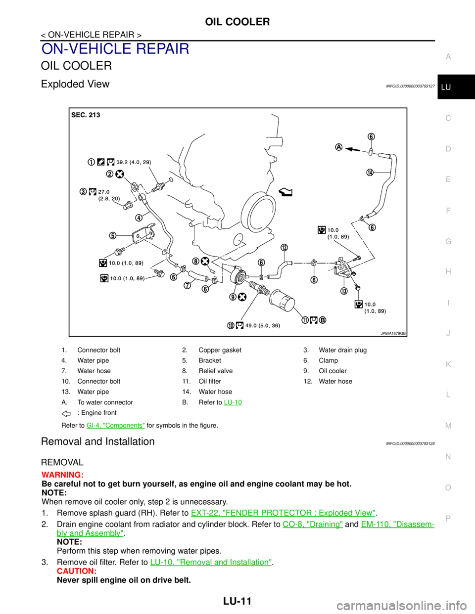
2. Insert oil level gauge and check the engine oil level is within the
range shown in the figure.
3. If it is out of range, adjust it.
ENGINE OIL APPEARANCE
Check engine oil for white turbidity or heavy contamination.
If engine oil becomes turbid and white, it is highly probable that it is contaminated with engine coolant.
Repair or replace damaged parts.
ENGINE OIL LEAKAGE
Check for engine oil leakage around the following areas:
Oil pans (lower and upper)
Oil pan drain plug
Oil pressure switch
Oil filter
Water pump cover
Oil cooler
Valve timing control covers (bank 1 and bank 2)
Mating surface between cylinder head and rocker cover
Mating surface between front timing chain case and rear timing chain case
Mating surface between rear timing chain case and cylinder head
Mating surface between rear timing chain case and cylinder block
Mating surface between rear timing chain case and oil pan (upper)
Mating surface between cylinder block and cylinder head
Crankshaft oil seals (front and rear)
Camshaft position sensor (PHASE)
OIL PRESSURE CHECK
WARNING:
• Be careful not to get burn yourself, as engine oil may be hot.
Oil pressure check should be done in “Parking position”.
1. Check the engine oil level. Refer to LU-7, "
Inspection".
2. Remove splash guard (RH). Refer to EXT-22, "
FENDER PROTECTOR : Exploded View".
PBIC4202E
Page 3183 of 5121

OIL COOLER
LU-11
< ON-VEHICLE REPAIR >
C
D
E
F
G
H
I
J
K
L
MA
LU
N
P O
ON-VEHICLE REPAIR
OIL COOLER
Exploded ViewINFOID:0000000003793127
Removal and InstallationINFOID:0000000003793128
REMOVAL
WARNING:
Be careful not to get burn yourself, as engine oil and engine coolant may be hot.
NOTE:
When remove oil cooler only, step 2 is unnecessary.
1. Remove splash guard (RH). Refer to EXT-22, "
FENDER PROTECTOR : Exploded View".
2. Drain engine coolant from radiator and cylinder block. Refer to CO-8, "
Draining" and EM-110, "Disassem-
bly and Assembly".
NOTE:
Perform this step when removing water pipes.
3. Remove oil filter. Refer to LU-10, "
Removal and Installation".
CAUTION:
Never spill engine oil on drive belt.
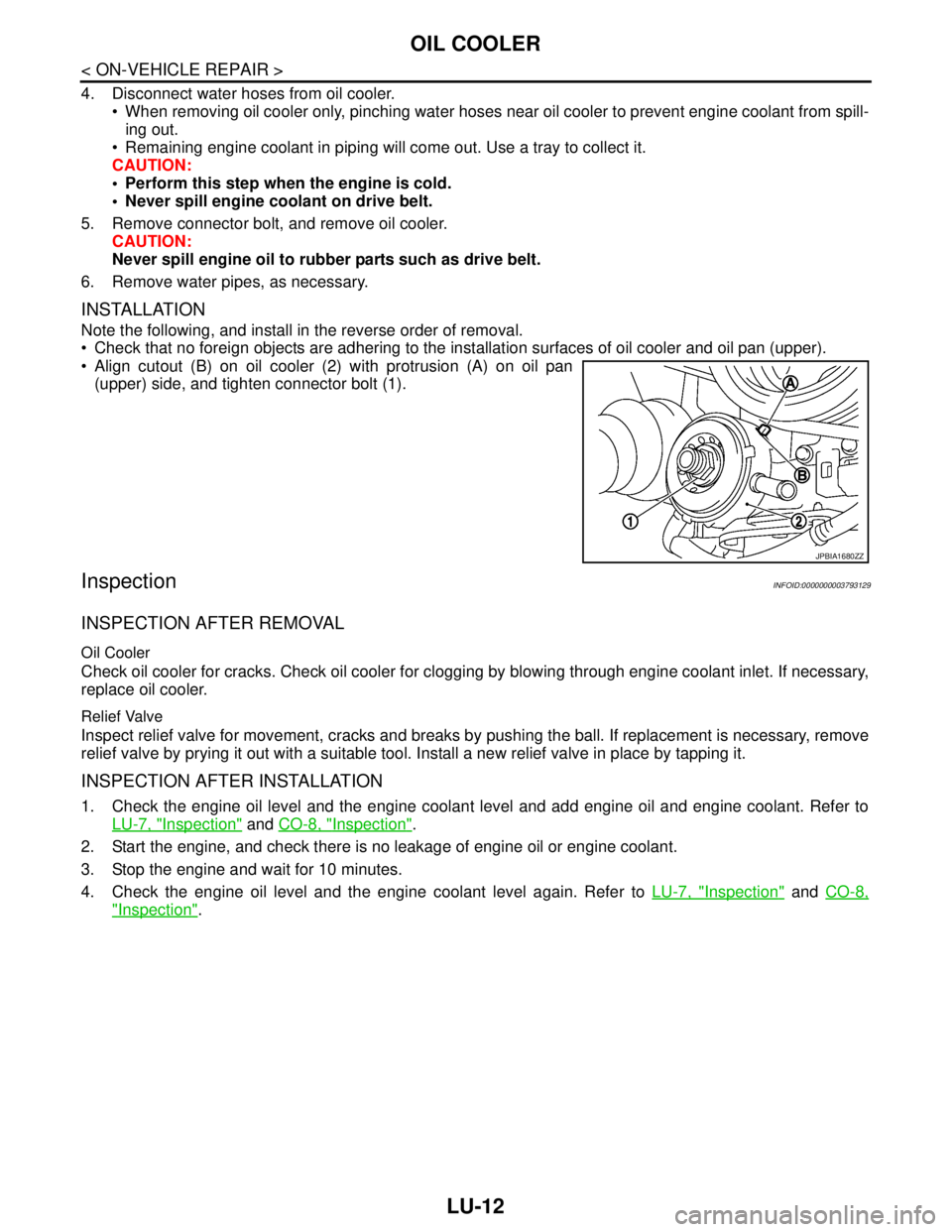
1. Connector bolt 2. Copper gasket 3. Water drain plug
4. Water pipe 5. Bracket 6. Clamp
7. Water hose 8. Relief valve 9. Oil cooler
10. Connector bolt 11. Oil filter 12. Water hose
13. Water pipe 14. Water hose
A. To water connector B. Refer to LU-10
: Engine front
Refer to GI-4, "
Components" for symbols in the figure.
JPBIA1679GB
Page 3184 of 5121

LU-12
< ON-VEHICLE REPAIR >
OIL COOLER
4. Disconnect water hoses from oil cooler.
When removing oil cooler only, pinching water hoses near oil cooler to prevent engine coolant from spill-
ing out.
Remaining engine coolant in piping will come out. Use a tray to collect it.
CAUTION:
Perform this step when the engine is cold.
Never spill engine coolant on drive belt.
5. Remove connector bolt, and remove oil cooler.
CAUTION:
Never spill engine oil to rubber parts such as drive belt.
6. Remove water pipes, as necessary.
INSTALLATION
Note the following, and install in the reverse order of removal.
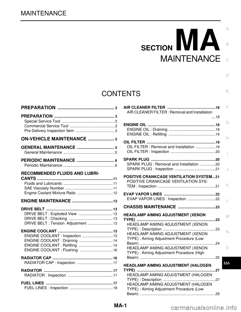
Check that no foreign objects are adhering to the installation surfaces of oil cooler and oil pan (upper).
Align cutout (B) on oil cooler (2) with protrusion (A) on oil pan
(upper) side, and tighten connector bolt (1).
InspectionINFOID:0000000003793129
INSPECTION AFTER REMOVAL
Oil Cooler
Check oil cooler for cracks. Check oil cooler for clogging by blowing through engine coolant inlet. If necessary,
replace oil cooler.
Relief Valve
Inspect relief valve for movement, cracks and breaks by pushing the ball. If replacement is necessary, remove
relief valve by prying it out with a suitable tool. Install a new relief valve in place by tapping it.
INSPECTION AFTER INSTALLATION
1. Check the engine oil level and the engine coolant level and add engine oil and engine coolant. Refer to
LU-7, "
Inspection" and CO-8, "Inspection".
2. Start the engine, and check there is no leakage of engine oil or engine coolant.
3. Stop the engine and wait for 10 minutes.
4. Check the engine oil level and the engine coolant level again. Refer to LU-7, "
Inspection" and CO-8,
"Inspection".
JPBIA1680ZZ
Page 3189 of 5121

MA-1
MAINTENANCE
C
DE
F
G H
I
J
K L
M B
MA
SECTION MA
N
O A
CONTENTS
MAINTENANCE
PREPARATION .............
...............................3
PREPARATION .............................................. .....3
Special Service Tool ........................................... ......3
Commercial Service Tool ..........................................3
Pre-Delivery Inspection Item .....................................3
ON-VEHICLE MAINTENANCE .....................5
GENERAL MAINTENANCE ........................... .....5
General Maintenance .......................................... ......5
PERIODIC MAINTENANCE ................................6
Periodic Maintenance .......................................... ......6
RECOMMENDED FLUIDS AND LUBRI-
CANTS ................................................................
11
Fluids and Lubricants .......................................... ....11
SAE Viscosity Number ............................................11
Engine Coolant Mixture Ratio .................................12
ENGINE MAINTENANCE ...................................13
DRIVE BELT .......................................................... ....13
DRIVE BELT : Exploded View ................................13
DRIVE BELT : Checking .........................................13
DRIVE BELT : Tension Adjustment ........................13
ENGINE COOLANT ............................................... ....13
ENGINE COOLANT : Inspection .............................13
ENGINE COOLANT : Draining ................................14
ENGINE COOLANT : Refilling ................................14
ENGINE COOLANT : Flushing ...............................16
RADIATOR CAP .................................................... ....16
RADIATOR CAP : Inspection ..................................17
RADIATOR ............................................................ ....17
RADIATOR : Inspection ..........................................17
FUEL LINES .......................................................... ....17
FUEL LINES : Inspection ........................................18
AIR CLEANER FILTER ......................................... ....18
AIR CLEANER FILTER : Removal and Installation
....
18
ENGINE OIL ........................................................... ....18
ENGINE OIL : Draining ............................................18
ENGINE OIL : Refilling ............................................19
OIL FILTER ............................................................ ....19
OIL FILTER : Removal and Installation ...................19
OIL FILTER : Inspection ..........................................20
SPARK PLUG ........................................................ ....20
SPARK PLUG : Removal and Installation ...............20
SPARK PLUG : Inspection ......................................21
POSITIVE CRANKCASE VENTILATION SYSTEM ....21
POSITIVE CRANKCASE VENTILATION SYS-
TEM : Inspection ......................................................
21
EVAP VAPOR LINES ............................................ ....22
EVAP VAPOR LINES : Inspection ...........................22
CHASSIS MAINTENANCE ...............................23
HEADLAMP AIMING ADJUSTMENT (XENON
TYPE) .......... ................................. ..............................
23
HEADLAMP AIMING ADJUSTMENT (XENON
TYPE) : Description ............................................. ....
23
HEADLAMP AIMING ADJUSTMENT (XENON
TYPE) : Aiming Adjustment Procedure (Low
Beam) ......................................................................
24
HEADLAMP AIMING ADJUSTMENT (XENON
TYPE) : Aiming Adjustment Procedure (High
Beam) ......................................................................
25
HEADLAMP AIMING ADJUSTMENT (HALOGEN
TYPE) ........................................... ..............................
27
HEADLAMP AIMING ADJUSTMENT (HALOGEN
TYPE) : Description ............................................. ....
27
HEADLAMP AIMING ADJUSTMENT (HALOGEN
TYPE) : Aiming Adjustment Procedure (Low
Beam) ......................................................................
29