2008 NISSAN QASHQAI High vent
[x] Cancel search: High ventPage 74 of 297
Downloaded from www.Manualslib.com manuals search engine Daytime light system (where fitted)
Even if the headlight switch is off, the headlight low
beam, front side, rear combination and number plate
lights will come on after starting the engine. How-
ever, you cannot change low beam to high beam
when the light switch is off.
When the light switch is turned to the
position,
the headlight low beam will turn off.
Autolight system (AUTO — where fitted)
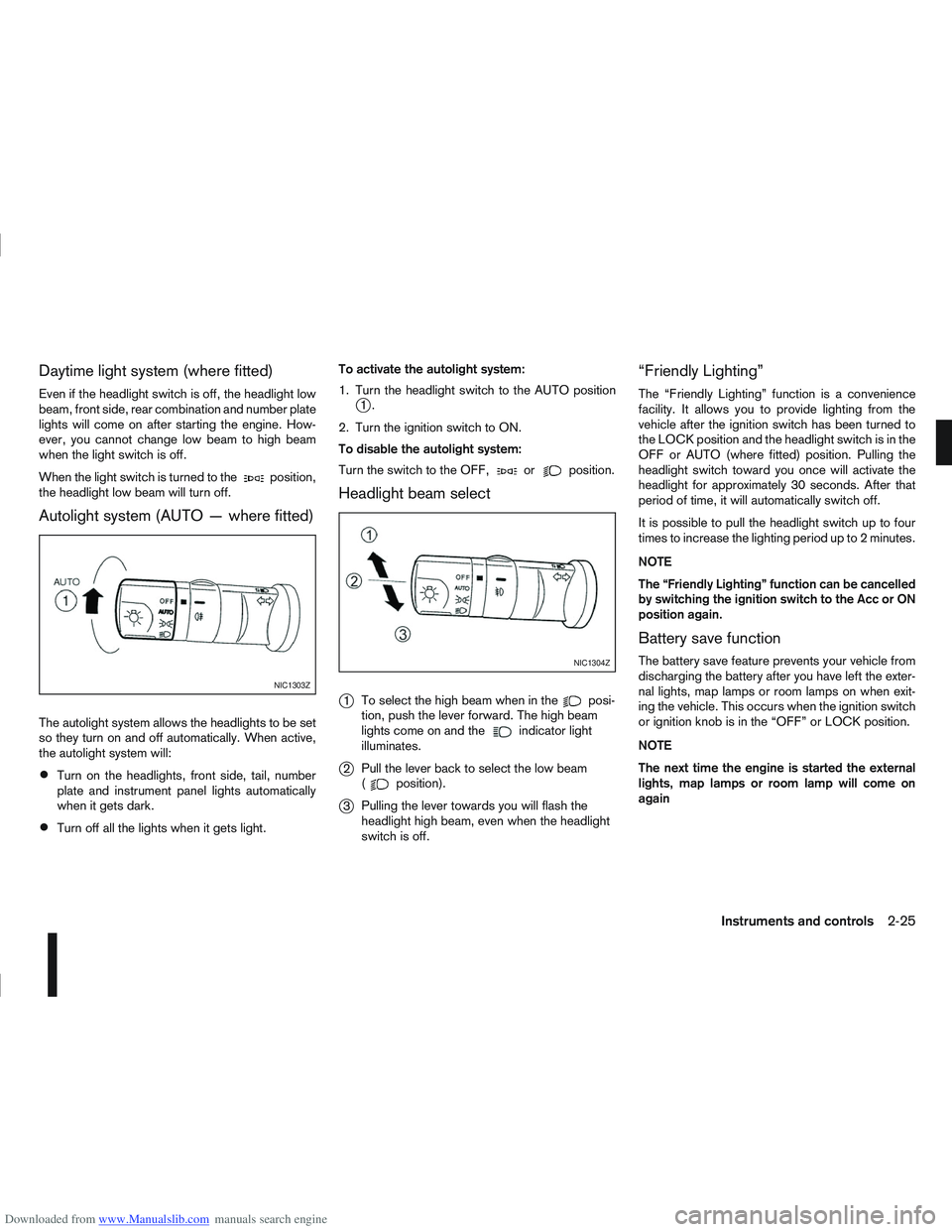
The autolight system allows the headlights to be set
so they turn on and off automatically. When active,
the autolight system will:
Turn on the headlights, front side, tail, number
plate and instrument panel lights automatically
when it gets dark.
Turn off all the lights when it gets light. To activate the autolight system:
1. Turn the headlight switch to the AUTO position
j1.
2. Turn the ignition switch to ON.
To disable the autolight system:
Turn the switch to the OFF,
orposition.
Headlight beam select
j
1 To select the high beam when in theposi-
tion, push the lever forward. The high beam
lights come on and the
indicator light
illuminates.
j2 Pull the lever back to select the low beam
(position).
j3Pulling the lever towards you will flash the
headlight high beam, even when the headlight
switch is off.
“Friendly Lighting”
The “Friendly Lighting” function is a convenience
facility. It allows you to provide lighting from the
vehicle after the ignition switch has been turned to
the LOCK position and the headlight switch is in the
OFF or AUTO (where fitted) position. Pulling the
headlight switch toward you once will activate the
headlight for approximately 30 seconds. After that
period of time, it will automatically switch off.
It is possible to pull the headlight switch up to four
times to increase the lighting period up to 2 minutes.
NOTE
The “Friendly Lighting” function can be cancelled
by switching the ignition switch to the Acc or ON
position again.
Battery save function
The battery save feature prevents your vehicle from
discharging the battery after you have left the exter-
nal lights, map lamps or room lamps on when exit-
ing the vehicle. This occurs when the ignition switch
or ignition knob is in the “OFF” or LOCK position.
NOTE
The next time the engine is started the external
lights, map lamps or room lamp will come on
again
NIC1303Z
NIC1304Z
Instruments and controls2-25
Page 82 of 297
Downloaded from www.Manualslib.com manuals search engine WARNING
Never put anything on the rear parcel shelf, no
matter how small. Any object on it could cause
an injury in an accident or when the brakes are
applied suddenly.
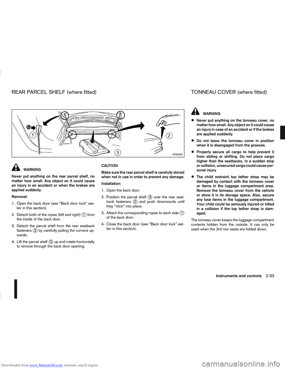
Removal:
1. Open the back door (see “Back door lock” ear- lier in this section).
2. Detach both of the ropes (left and right)
j1 from
the inside of the back door.
3. Detach the parcel shelf from the rear seatback fasteners
j2 by carefully pulling the corners up-
wards.
4. Lift the parcel shelf
j3 up and rotate horizontally
to remove through the back door opening. CAUTION
Make sure the rear parcel shelf is carefully stored
when not in use in order to prevent any damage.
Installation:
1. Open the back door.
2. Position the parcel shelf
j3 over the rear seat-
back fastenersj2 and push downwards until
they “click” into place.
3. Attach the corresponding ropes to each side
j1
of the back door.
4. Close the back door (see “Back door lock” ear- lier in this section).
WARNING
Never put anything on the tonneau cover, no
matter how small. Any object on it could cause
an injury in case of an accident or if the brakes
are applied suddenly.
Do not leave the tonneau cover in position
when it is disengaged from the grooves.
Properly secure all cargo to help prevent it
from sliding or shifting. Do not place cargo
higher than the seatbacks. In a sudden stop
or collision, unsecured cargo could cause per-
sonal injury
The child restraint top tether strap may be
damaged by contact with the tonneau cover
or items in the luggage compartment area.
Remove the tonneau cover from the vehicle
or store it in its storage space. Also, secure
any lose items in the luggage compartment.
Your child could be seriously injured or killed
in a collision if the top tether strap is dam-
aged.
The tonneau cover keeps the luggage compartment
contents hidden from the outside. It can only be
used when the 3rd row seats are folded down.
NPA838Z
REAR PARCEL SHELF (where fitted) TONNEAU COVER (where fitted)
Instruments and controls2-33
Page 85 of 297
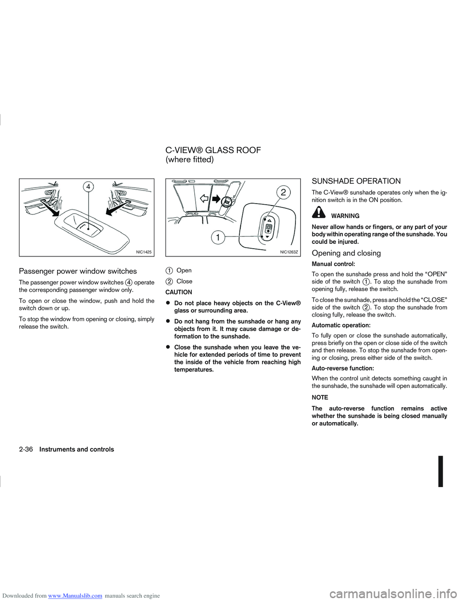
Downloaded from www.Manualslib.com manuals search engine Passenger power window switches
The passenger power window switchesj4 operate
the corresponding passenger window only.
To open or close the window, push and hold the
switch down or up.
To stop the window from opening or closing, simply
release the switch.
j1 Open
j2Close
CAUTION
Do not place heavy objects on the C-View®
glass or surrounding area.
Do not hang from the sunshade or hang any
objects from it. It may cause damage or de-
formation to the sunshade.
Close the sunshade when you leave the ve-
hicle for extended periods of time to prevent
the inside of the vehicle from reaching high
temperatures.
SUNSHADE OPERATION
The C-View® sunshade operates only when the ig-
nition switch is in the ON position.
WARNING
Never allow hands or fingers, or any part of your
body within operating range of the sunshade. You
could be injured.
Opening and closing
Manual control:
To open the sunshade press and hold the “OPEN”
side of the switch
j1 . To stop the sunshade from
opening fully, release the switch.
To close the sunshade, press and hold the “CLOSE”
side of the switch
j2 . To stop the sunshade from
closing fully, release the switch.
Automatic operation:
To fully open or close the sunshade automatically,
press briefly on the open or close side of the switch
and then release. To stop the sunshade from open-
ing or closing, press either side of the switch.
Auto-reverse function:
When the control unit detects something caught in
the sunshade, the sunshade will open automatically.
NOTE
The auto-reverse function remains active
whether the sunshade is being closed manually
or automatically.
NIC1425NIC1263Z
C-VIEW® GLASS ROOF
(where fitted)
2-36Instruments and controls
Page 102 of 297
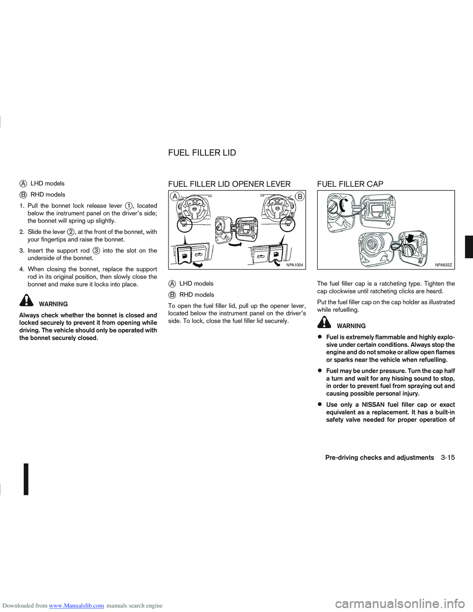
Downloaded from www.Manualslib.com manuals search engine jALHD models
jB RHD models
1. Pull the bonnet lock release lever
j1 , located
below the instrument panel on the driver’s side;
the bonnet will spring up slightly.
2. Slide the lever
j2 , at the front of the bonnet, with
your fingertips and raise the bonnet.
3. Insert the support rod
j3 into the slot on the
underside of the bonnet.
4. When closing the bonnet, replace the support rod in its original position, then slowly close the
bonnet and make sure it locks into place.
WARNING
Always check whether the bonnet is closed and
locked securely to prevent it from opening while
driving. The vehicle should only be operated with
the bonnet securely closed.
FUEL FILLER LID OPENER LEVER
j
A LHD models
jB RHD models
To open the fuel filler lid, pull up the opener lever,
located below the instrument panel on the driver’s
side. To lock, close the fuel filler lid securely.
FUEL FILLER CAP
The fuel filler cap is a ratcheting type. Tighten the
cap clockwise until ratcheting clicks are heard.
Put the fuel filler cap on the cap holder as illustrated
while refuelling.
WARNING
Fuel is extremely flammable and highly explo-
sive under certain conditions. Always stop the
engine and do not smoke or allow open flames
or sparks near the vehicle when refuelling.
Fuel may be under pressure. Turn the cap half
a turn and wait for any hissing sound to stop,
in order to prevent fuel from spraying out and
causing possible personal injury.
Use only a NISSAN fuel filler cap or exact
equivalent as a replacement. It has a built-in
safety valve needed for proper operation of
NPA1004NPA832Z
FUEL FILLER LID
Pre-driving checks and adjustments3-15
Page 108 of 297
Downloaded from www.Manualslib.com manuals search engine 4Display screen, heater and air conditioner,
and audio system
Display screen, heater and air conditioner,
and
audio system
Rear-view monitor (where fitted)............................... 4-2
How to read the displayed lines .......................... 4-2
Rear-view monitor setting.................................... 4-3
Operating tips..................................................... 4-3
Around view monitor (where fitted)........................... 4-4 Operation ........................................................... 4-6
Guide lines ......................................................... 4-7
Difference between predictive and actual
distances ............................................................ 4-9
How to adjust the screen view ............................ 4-11
Operating tips..................................................... 4-11
Vents ....................................................................... 4-12 Side and centre vents ......................................... 4-12
High level vent (where fitted) ............................... 4-12
Heater and air conditioner operation ........................ 4-12 Manual air conditioner......................................... 4-13
Automatic air conditioner (where fitted) ............... 4-18
Audio system ........................................................... 4-21 Audio operation precautions ............................... 4-21
Antenna .............................................................. 4-22
LW-MW-FM radio with CD player or 6 CD
changer ................................................................... 4-23 Anti-theft system ................................................. 4-24
Audio main operation .......................................... 4-24
Radio operation .................................................. 4-24
MENU button...................................................... 4-27 Compact Disc (CD) operation ............................ 4-27
AUX socket ........................................................ 4-29
Bluetooth® mobile phone feature ........................ 4-29
FM AM radio with CD player.................................... 4-30 Anti-theft system ................................................. 4-31
Audio main operation .......................................... 4-31
Radio operation .................................................. 4-32
SETUP button .................................................... 4-33
Compact Disc (CD) operation ............................ 4-35
AUX socket ........................................................ 4-36
USB Memory operation (where fitted) ................. 4-37
iPod® player operation (where fitted) .................. 4-37
Bluetooth® operation.......................................... 4-39
NISSAN Connect (where fitted) ............................... 4-43
Steering wheel switch for audio control (where
fitted) ....................................................................... 4-43 Main operation .................................................... 4-43
Car phone or CB radio ............................................ 4-44
Mobile phone integration for LW-MW-FM radio
with CD player or 6 CD changer (Type A) ................ 4-44 Bluetooth® mobile phone feature ........................ 4-44
Mobile phone integration for FM AM radio with
CD player ................................................................ 4-52 Bluetooth® mobile phone feature ........................ 4-52
Hands-free telephone control .............................. 4-53
Steering wheel switches (where fitted) ................ 4-55
Page 119 of 297
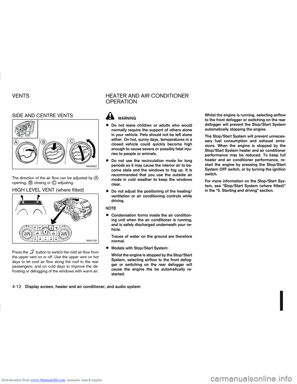
Downloaded from www.Manualslib.com manuals search engine SIDE AND CENTRE VENTS
The direction of the air flow can be adjusted byjA
opening,jB closing orjC adjusting.
HIGH LEVEL VENT (where fitted)
Press thebutton to switch the mild air flow from
the upper vent on or off. Use the upper vent on hot
days to let cool air flow along the roof to the rear
passengers; and on cold days to improve the de-
frosting or defogging of the windows with warm air.
WARNING
Do not leave children or adults who would
normally require the support of others alone
in your vehicle. Pets should not be left alone
either. On hot, sunny days, temperatures in a
closed vehicle could quickly become high
enough to cause severe or possibly fatal inju-
ries to people or animals.
Do not use the recirculation mode for long
periods as it may cause the interior air to be-
come stale and the windows to fog up. It is
recommended that you use the outside air
mode in cold weather to keep the windows
clear.
Do not adjust the positioning of the heating/
ventilation or air conditioning controls while
driving.
NOTE
Condensation forms inside the air condition-
ing unit when the air conditioner is running,
and is safely discharged underneath your ve-
hicle.
Traces of water on the ground are therefore
normal.
Models with Stop/Start System:
Whilst the engine is stopped by the Stop/Start
System, selecting airflow to the front defog-
ger or switching on the rear defogger will
cause the engine the be automatically re-
started. Whilst the engine is running, selecting airflow
to the front defogger or switching on the rear
defogger will prevent the Stop/Start System
automatically stopping the engine.
The Stop/Start System will prevent unneces-
sary fuel consumption and exhaust emis-
sions. When the engine is stopped by the
Stop/Start System heater and air conditioner
performance may be reduced. To keep full
heater and air conditioner performance, re-
start the engine by pressing the Stop/Start
System OFF switch, or by turning the ignition
switch.
For more information on the Stop/Start Sys-
tem, see “Stop/Start System (where fitted)”
in the “5. Starting and driving” section.
NAA945Z
NAA1150
VENTS
HEATER AND AIR CONDITIONER
OPERATION
4-12Display screen, heater and air conditioner, and audio system
Page 121 of 297
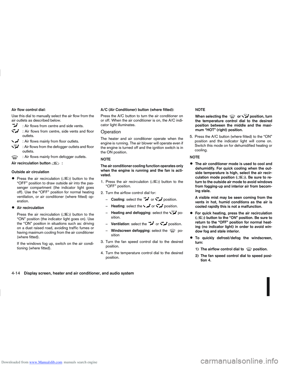
Downloaded from www.Manualslib.com manuals search engine Air flow control dial:
Use this dial to manually select the air flow from the
air outlets as described below.
: Air flows from centre and side vents.
: Air flows from centre, side vents and floor
outlets.
: Air flows mainly from floor outlets.
: Air flows from the defogger outlets and floor
outlets.
: Air flows mainly from defogger outlets.
Air recirculation button
m:
Outside air circulation
Press the air recirculation () button to the
“OFF” position to draw outside air into the pas-
senger compartment (the indicator light goes
off). Use the “OFF” position for normal heating
ventilation, or air conditioner (where fitted) op-
eration.
Air recirculation
Press the air recirculation (
) button to the
“ON” position (the indicator light goes on). Use
the “ON” position in situations such as: driving
on a dust raised road, avoiding traffic fumes or
having maximum cooling from the air conditioner
(where fitted).
If the windows fog up, switch on the air condi-
tioning (where fitted). A/C (Air Conditioner) button (where fitted):
Press the A/C button to turn the air conditioner on
or off. When the air conditioner is on, the A/C indi-
cator light illuminates.
Operation
The heater and air conditioner operate when the
engine is running. The air blower will operate even if
the engine is turned off and the ignition switch is in
the ON position.
NOTE
The air conditioner cooling function operates only
when the engine is running and the fan is acti-
vated.
1. Press the air recirculation (
) button to the
“OFF” position.
2. Turn the airflow control dial for: – Cooling: select the
orposition.
– Heating: select the
orposition.
– Heating and defogging : select the
po-
sition.
– Ventilation : select the
orposition.
– Windscreen defogging : select the
po-
sition
3. Turn the fan speed control dial to the desired position.
4. Turn the temperature control dial to the desired position. NOTE
When selecting the
orposition, turn
the temperature control dial to the desired
position between the middle and the maxi-
mum “HOT” (right) position.
5. Press the A/C button (where fitted) to the “ON” position and the indicator light will come on.
Switch this mode on for dehumidified heating or
cooling.
NOTE
The air conditioner mode is used to cool and
dehumidify. For quick cooling when the out-
side temperature is high, select the air recir-
culation mode position (
). Be sure to re-
turn to the outside air mode to avoid windows
from fogging-up and interior air from becom-
ing stale.
A visible mist may be seen coming from the
vents in hot, humid conditions as the air is
cooled rapidly this is not a malfunction.
For quick heating, press the air recirculation
() button to the “ON” position. Be sure to
return to the “OFF” position for normal heat-
ing (no indicator light) in order to avoid win-
dow fog and stale interior.
To quickly defrost/defog the windscreen,
turn:
1) The airflow control dial to
position.
2) The fan speed control dial to speed posi- tion 4.
4-14Display screen, heater and air conditioner, and audio system
Page 122 of 297
Downloaded from www.Manualslib.com manuals search engine 3) The temperature control dial to the maxi-mum “HOT” (right) position.
Operating tips
In order to improve the heater operation, clear
the snow and ice from the wiper blade and air
inlet in front of the windscreen.
After parking in the sun, drive for two or three
minutes with the windows open to vent hot air
from the passenger compartment. Then close
the windows to allow the acceleration of the air
conditioner’s cooling operation.
Keep the windows closed while the air condi-
tioner is operating.
The air conditioning system should be operated
for about 10 minutes, at least once a month. This
helps prevent damage to the system due to lack
of lubrication.
If the coolant temperature gauge exceeds the
“HOT” position, turn the air conditioner off. For
additional information, see “Engine overheat” in
the “6. In case of emergency” section.
If the engine coolant reaches an extremely high
temperature, the air conditioning system will au-
tomatically turn off. This may happen for example
if the engine runs at idle speed for a long time on
a hot day.
Quick reference charts
The following charts show the button, air intake and
dial positions for MAXIMUM AND QUICK heating,
cooling or defrosting. NOTE
The air recirculation mode should not be selected
for either heating or defrosting.
Display screen, heater and air conditioner, and audio system4-15