2008 NISSAN LATIO trunk
[x] Cancel search: trunkPage 630 of 2771

BL-196
< SERVICE INFORMATION >
VEHICLE SECURITY (THEFT WARNING) SYSTEM
CONSULT-III Function (BCM)
INFOID:0000000001704090
CONSULT-III can display each diagnostic item using the diagnostic test modes shown following.
CONSULT-III APPLICATION ITEM
Work Support
Data Monitor
* : With remote keyless entry system
** : With Intelligent Key systemBCM
diagnostic test itemDiagnostic mode Description
Inspection by partWORK SUPPORTSupports inspections and adjustments. Commands are transmitted to the
BCM for setting the status suitable for required operation, input/output sig-
nals are received from the BCM and received date is displayed.
DATA MONITOR Displays BCM input/output data in real time.
ACTIVE TESTOperation of electrical loads can be checked by sending drive signal to
them.
SELF-DIAG RESULTS Displays BCM self-diagnosis results.
CAN DIAG SUPPORT MNTRThe result of transmit/receive diagnosis of CAN communication can be
read.
ECU PART NUMBER BCM part number can be read.
CONFIGURATION Performs BCM configuration read/write functions.
Test Item Description
SECURITY ALARM SET This mode can confirm and change security alarm ON-OFF setting.
THEFT ALM TRGThe switch which triggered vehicle security alarm is recorded. This mode is able to confirm and
erase the record of vehicle security alarm. The trigger data can be erased by touching “CLEAR” on
CONSULT-III screen.
Monitored Item Description
IGN ON SW Indicates [ON/OFF] condition of ignition switch.
ACC ON SW Indicates [ON/OFF] condition of ignition switch in ACC position.
KEYLESS LOCK* Indicates [ON/OFF] condition of lock signal from keyfob.
KEYLESS UNLOCK* Indicates [ON/OFF] condition of unlock signal from keyfob.
I-KEY LOCK** Indicates [ON/OFF] condition of lock signal from keyfob.
I-KEY UNLOCK** Indicates [ON/OFF] condition of unlock signal from keyfob.
I-KEY TRUNK** Indicates [ON/OFF] condition of trunk open signal from keyfob.
TRNK OPNR SW Indicates [ON/OFF] condition of trunk opener switch.
TRUNK CYL SW Indicates [ON/OFF] condition of trunk key cylinder switch.
TRNK OPN MNTR Indicates [ON/OFF] condition of trunk lid status.
DOOR SW-DR Indicates [ON/OFF] condition of front door switch LH.
DOOR SW-AS Indicates [ON/OFF] condition of front door switch RH.
DOOR SW-RR Indicates [ON/OFF] condition of rear door switch RH.
DOOR SW-RL Indicates [ON/OFF] condition of rear door switch LH.
BACK DOOR SW Indicates [ON/OFF] condition of back door switch.
KEY CYL LK SW Indicates [ON/OFF] condition of lock signal from key cylinder switch.
KEY CYL UN SW Indicates [ON/OFF] condition of unlock signal from key cylinder switch.
CDL LOCK SW Indicates [ON/OFF] condition of lock signal from door lock/unlock switch LH and RH.
CDL UNLOCK SW Indicates [ON/OFF] condition of unlock signal from door lock/unlock switch LH and RH.
Page 633 of 2771
VEHICLE SECURITY (THEFT WARNING) SYSTEM
BL-199
< SERVICE INFORMATION >
C
D
E
F
G
H
J
K
L
MA
B
BL
N
O
P
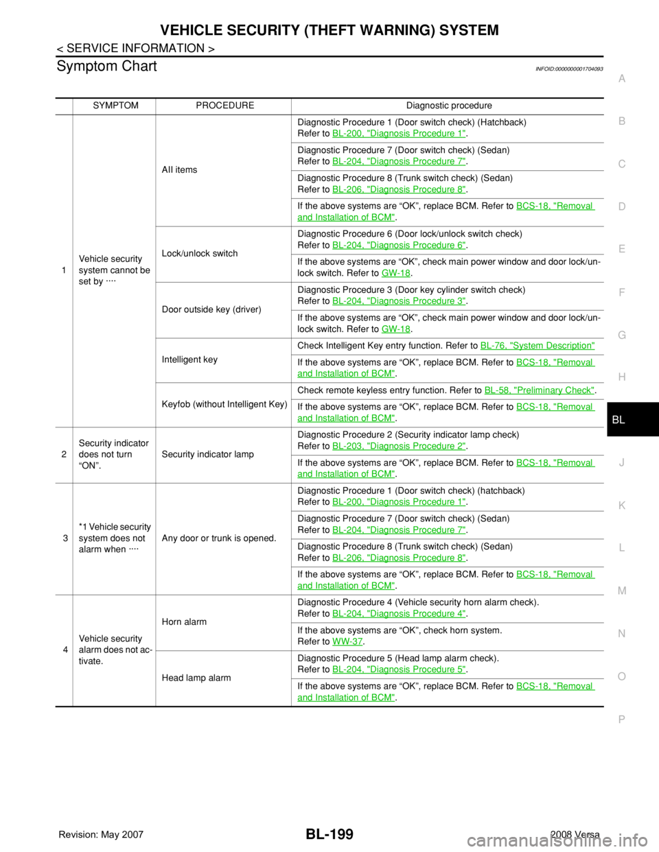
Symptom ChartINFOID:0000000001704093
SYMPTOM PROCEDURE Diagnostic procedure
1Vehicle security
system cannot be
set by ····AII itemsDiagnostic Procedure 1 (Door switch check) (Hatchback)
Refer to BL-200, "
Diagnosis Procedure 1".
Diagnostic Procedure 7 (Door switch check) (Sedan)
Refer to BL-204, "
Diagnosis Procedure 7".
Diagnostic Procedure 8 (Trunk switch check) (Sedan)
Refer to BL-206, "
Diagnosis Procedure 8".
If the above systems are “OK”, replace BCM. Refer to BCS-18, "
Removal
and Installation of BCM".
Lock/unlock switchDiagnostic Procedure 6 (Door lock/unlock switch check)
Refer to BL-204, "
Diagnosis Procedure 6".
If the above systems are “OK”, check main power window and door lock/un-
lock switch. Refer to GW-18
.
Door outside key (driver)Diagnostic Procedure 3 (Door key cylinder switch check)
Refer to BL-204, "
Diagnosis Procedure 3".
If the above systems are “OK”, check main power window and door lock/un-
lock switch. Refer to GW-18
.
Intelligent keyCheck Intelligent Key entry function. Refer to BL-76, "
System Description"
If the above systems are “OK”, replace BCM. Refer to BCS-18, "Removal
and Installation of BCM".
Keyfob (without Intelligent Key)Check remote keyless entry function. Refer to BL-58, "
Preliminary Check".
If the above systems are “OK”, replace BCM. Refer to BCS-18, "
Removal
and Installation of BCM".
2Security indicator
does not turn
“ON”.Security indicator lampDiagnostic Procedure 2 (Security indicator lamp check)
Refer to BL-203, "
Diagnosis Procedure 2".
If the above systems are “OK”, replace BCM. Refer to BCS-18, "
Removal
and Installation of BCM".
3*1 Vehicle security
system does not
alarm when ····Any door or trunk is opened.Diagnostic Procedure 1 (Door switch check) (hatchback)
Refer to BL-200, "
Diagnosis Procedure 1".
Diagnostic Procedure 7 (Door switch check) (Sedan)
Refer to BL-204, "
Diagnosis Procedure 7".
Diagnostic Procedure 8 (Trunk switch check) (Sedan)
Refer to BL-206, "
Diagnosis Procedure 8".
If the above systems are “OK”, replace BCM. Refer to BCS-18, "
Removal
and Installation of BCM".
4Vehicle security
alarm does not ac-
tivate.Horn alarmDiagnostic Procedure 4 (Vehicle security horn alarm check).
Refer to BL-204, "
Diagnosis Procedure 4".
If the above systems are “OK”, check horn system.
Refer to WW-37
.
Head lamp alarmDiagnostic Procedure 5 (Head lamp alarm check).
Refer to BL-204, "
Diagnosis Procedure 5".
If the above systems are “OK”, replace BCM. Refer to BCS-18, "
Removal
and Installation of BCM".
Page 634 of 2771
BL-200
< SERVICE INFORMATION >
VEHICLE SECURITY (THEFT WARNING) SYSTEM
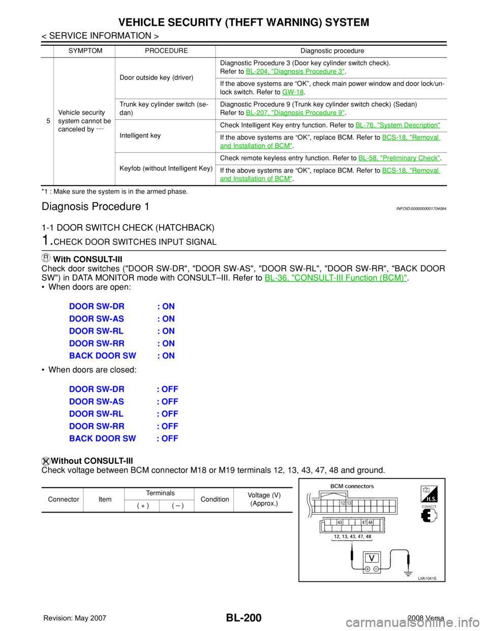
*1 : Make sure the system is in the armed phase.
Diagnosis Procedure 1INFOID:0000000001704094
1-1 DOOR SWITCH CHECK (HATCHBACK)
1.CHECK DOOR SWITCHES INPUT SIGNAL
With CONSULT-III
Check door switches ("DOOR SW-DR", "DOOR SW-AS", "DOOR SW-RL", "DOOR SW-RR", "BACK DOOR
SW") in DATA MONITOR mode with CONSULT–III. Refer to BL-36, "
CONSULT-III Function (BCM)".
• When doors are open:
• When doors are closed:
Without CONSULT-III
Check voltage between BCM connector M18 or M19 terminals 12, 13, 43, 47, 48 and ground.
5Vehicle security
system cannot be
canceled by ····Door outside key (driver)Diagnostic Procedure 3 (Door key cylinder switch check).
Refer to BL-204, "
Diagnosis Procedure 3".
If the above systems are “OK”, check main power window and door lock/un-
lock switch. Refer to GW-18
.
Trunk key cylinder switch (se-
dan)Diagnostic Procedure 9 (Trunk key cylinder switch check) (Sedan)
Refer to BL-207, "
Diagnosis Procedure 9".
Intelligent keyCheck Intelligent Key entry function. Refer to BL-76, "
System Description"
If the above systems are “OK”, replace BCM. Refer to BCS-18, "Removal
and Installation of BCM".
Keyfob (without Intelligent Key)Check remote keyless entry function. Refer to BL-58, "
Preliminary Check".
If the above systems are “OK”, replace BCM. Refer to BCS-18, "
Removal
and Installation of BCM". SYMPTOM PROCEDURE Diagnostic procedure
DOOR SW-DR : ON
DOOR SW-AS : ON
DOOR SW-RL : ON
DOOR SW-RR : ON
BACK DOOR SW : ON
DOOR SW-DR : OFF
DOOR SW-AS : OFF
DOOR SW-RL : OFF
DOOR SW-RR : OFF
BACK DOOR SW : OFF
Connector ItemTe r m i n a l s
ConditionVoltage (V)
(Approx.)
( + ) ( – )
LIIA1041E
Page 640 of 2771
BL-206
< SERVICE INFORMATION >
VEHICLE SECURITY (THEFT WARNING) SYSTEM
OK >> GO TO 3.
NG >> Repair or replace harness.
3.CHECK DOOR SWITCHES
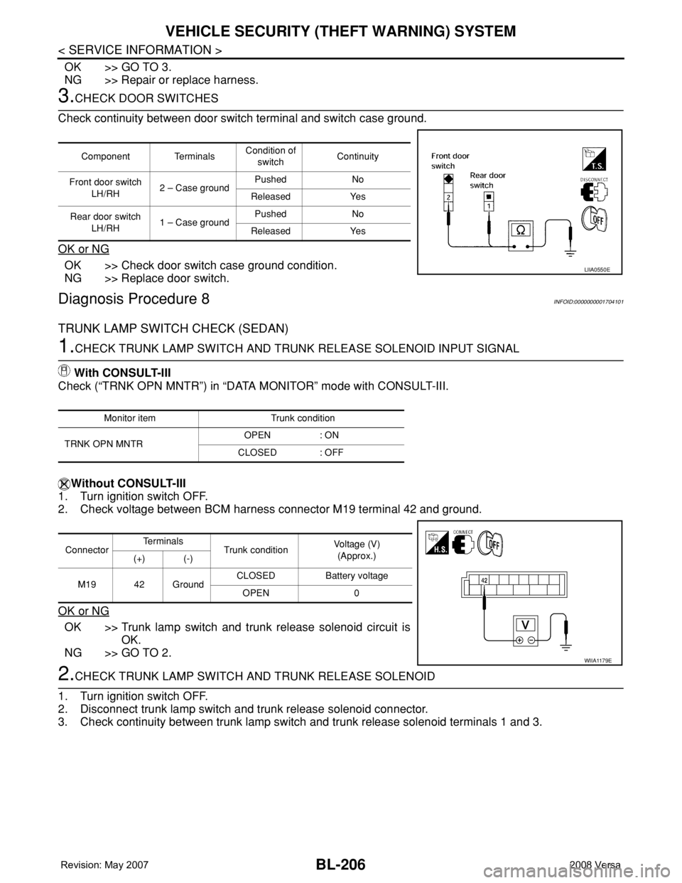
Check continuity between door switch terminal and switch case ground.
OK or NG
OK >> Check door switch case ground condition.
NG >> Replace door switch.
Diagnosis Procedure 8INFOID:0000000001704101
TRUNK LAMP SWITCH CHECK (SEDAN)
1.CHECK TRUNK LAMP SWITCH AND TRUNK RELEASE SOLENOID INPUT SIGNAL
With CONSULT-III
Check (“TRNK OPN MNTR”) in “DATA MONITOR” mode with CONSULT-III.
Without CONSULT-III
1. Turn ignition switch OFF.
2. Check voltage between BCM harness connector M19 terminal 42 and ground.
OK or NG
OK >> Trunk lamp switch and trunk release solenoid circuit is
OK.
NG >> GO TO 2.
2.CHECK TRUNK LAMP SWITCH AND TRUNK RELEASE SOLENOID
1. Turn ignition switch OFF.
2. Disconnect trunk lamp switch and trunk release solenoid connector.
3. Check continuity between trunk lamp switch and trunk release solenoid terminals 1 and 3.
Component TerminalsCondition of
switchContinuity
Front door switch
LH/RH2 – Case groundPushed No
Released Yes
Rear door switch
LH/RH1 – Case groundPushed No
Released Yes
LIIA0550E
Monitor item Trunk condition
TRNK OPN MNTROPEN : ON
CLOSED : OFF
ConnectorTe r m i n a l s
Trunk conditionVoltage (V)
(Approx.)
(+) (-)
M19 42 GroundCLOSED Battery voltage
OPEN 0
WIIA1179E
Page 641 of 2771
VEHICLE SECURITY (THEFT WARNING) SYSTEM
BL-207
< SERVICE INFORMATION >
C
D
E
F
G
H
J
K
L
MA
B
BL
N
O
P
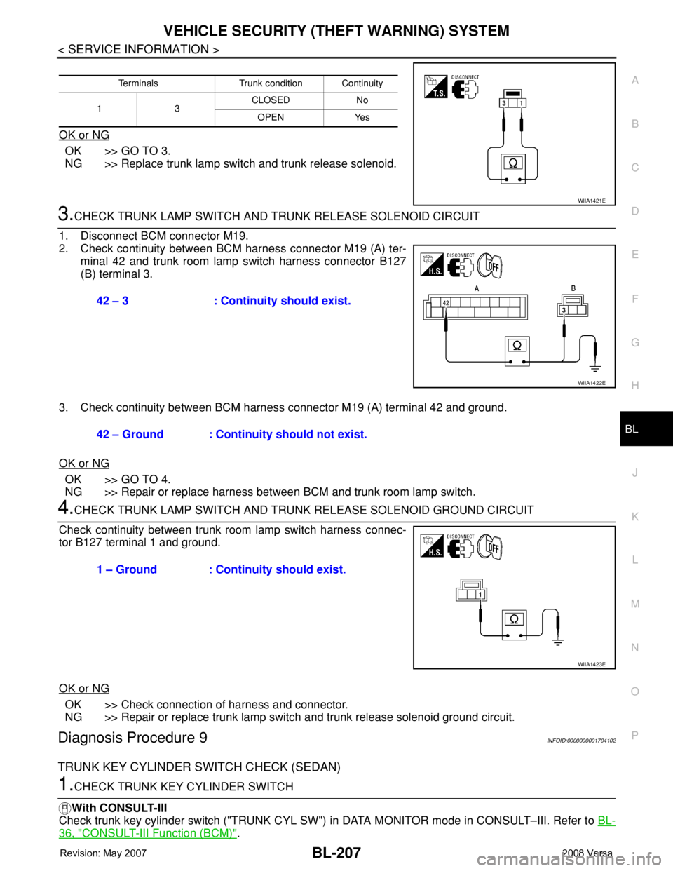
OK or NG
OK >> GO TO 3.
NG >> Replace trunk lamp switch and trunk release solenoid.
3.CHECK TRUNK LAMP SWITCH AND TRUNK RELEASE SOLENOID CIRCUIT
1. Disconnect BCM connector M19.
2. Check continuity between BCM harness connector M19 (A) ter-
minal 42 and trunk room lamp switch harness connector B127
(B) terminal 3.
3. Check continuity between BCM harness connector M19 (A) terminal 42 and ground.
OK or NG
OK >> GO TO 4.
NG >> Repair or replace harness between BCM and trunk room lamp switch.
4.CHECK TRUNK LAMP SWITCH AND TRUNK RELEASE SOLENOID GROUND CIRCUIT
Check continuity between trunk room lamp switch harness connec-
tor B127 terminal 1 and ground.
OK or NG
OK >> Check connection of harness and connector.
NG >> Repair or replace trunk lamp switch and trunk release solenoid ground circuit.
Diagnosis Procedure 9INFOID:0000000001704102
TRUNK KEY CYLINDER SWITCH CHECK (SEDAN)
1.CHECK TRUNK KEY CYLINDER SWITCH
With CONSULT-III
Check trunk key cylinder switch ("TRUNK CYL SW") in DATA MONITOR mode in CONSULT–III. Refer to BL-
36, "CONSULT-III Function (BCM)".
Terminals Trunk condition Continuity
13CLOSED No
OPEN Yes
WIIA1421E
42 – 3 : Continuity should exist.
WIIA1422E
42 – Ground : Continuity should not exist.
1 – Ground : Continuity should exist.
WIIA1423E
Page 642 of 2771
BL-208
< SERVICE INFORMATION >
VEHICLE SECURITY (THEFT WARNING) SYSTEM
• When key inserted in trunk key cylinder is turned to FULL STROKE:
• When key is removed from the trunk key cylinder:
Without CONSULT-III
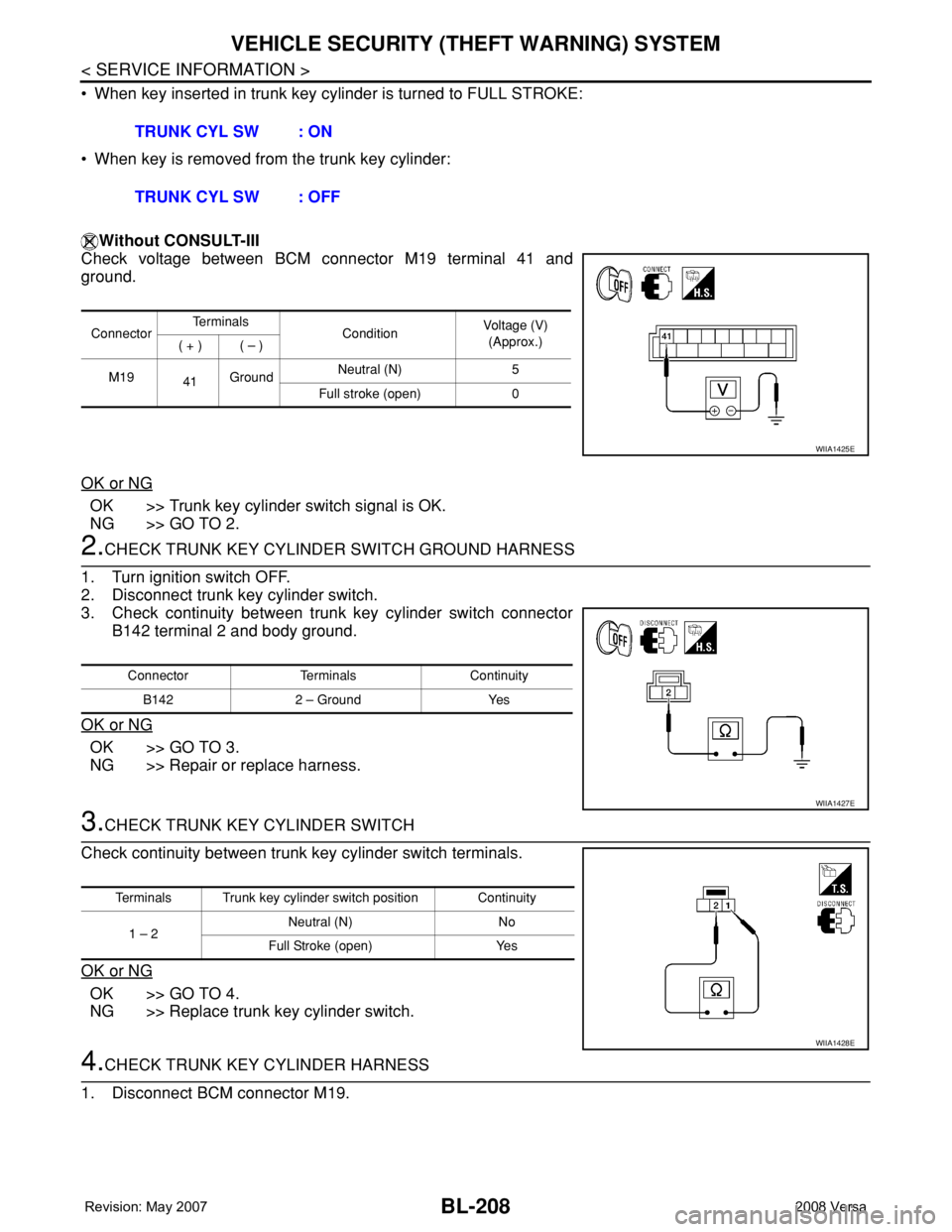
Check voltage between BCM connector M19 terminal 41 and
ground.
OK or NG
OK >> Trunk key cylinder switch signal is OK.
NG >> GO TO 2.
2.CHECK TRUNK KEY CYLINDER SWITCH GROUND HARNESS
1. Turn ignition switch OFF.
2. Disconnect trunk key cylinder switch.
3. Check continuity between trunk key cylinder switch connector
B142 terminal 2 and body ground.
OK or NG
OK >> GO TO 3.
NG >> Repair or replace harness.
3.CHECK TRUNK KEY CYLINDER SWITCH
Check continuity between trunk key cylinder switch terminals.
OK or NG
OK >> GO TO 4.
NG >> Replace trunk key cylinder switch.
4.CHECK TRUNK KEY CYLINDER HARNESS
1. Disconnect BCM connector M19.TRUNK CYL SW : ON
TRUNK CYL SW : OFF
ConnectorTe r m i n a l s
ConditionVoltage (V)
(Approx.)
( + ) ( – )
M19
41GroundNeutral (N) 5
Full stroke (open) 0
WIIA1425E
Connector Terminals Continuity
B142 2 – Ground Yes
WIIA1427E
Terminals Trunk key cylinder switch position Continuity
1 – 2 Neutral (N) No
Full Stroke (open) Yes
WIIA1428E
Page 643 of 2771
VEHICLE SECURITY (THEFT WARNING) SYSTEM
BL-209
< SERVICE INFORMATION >
C
D
E
F
G
H
J
K
L
MA
B
BL
N
O
P
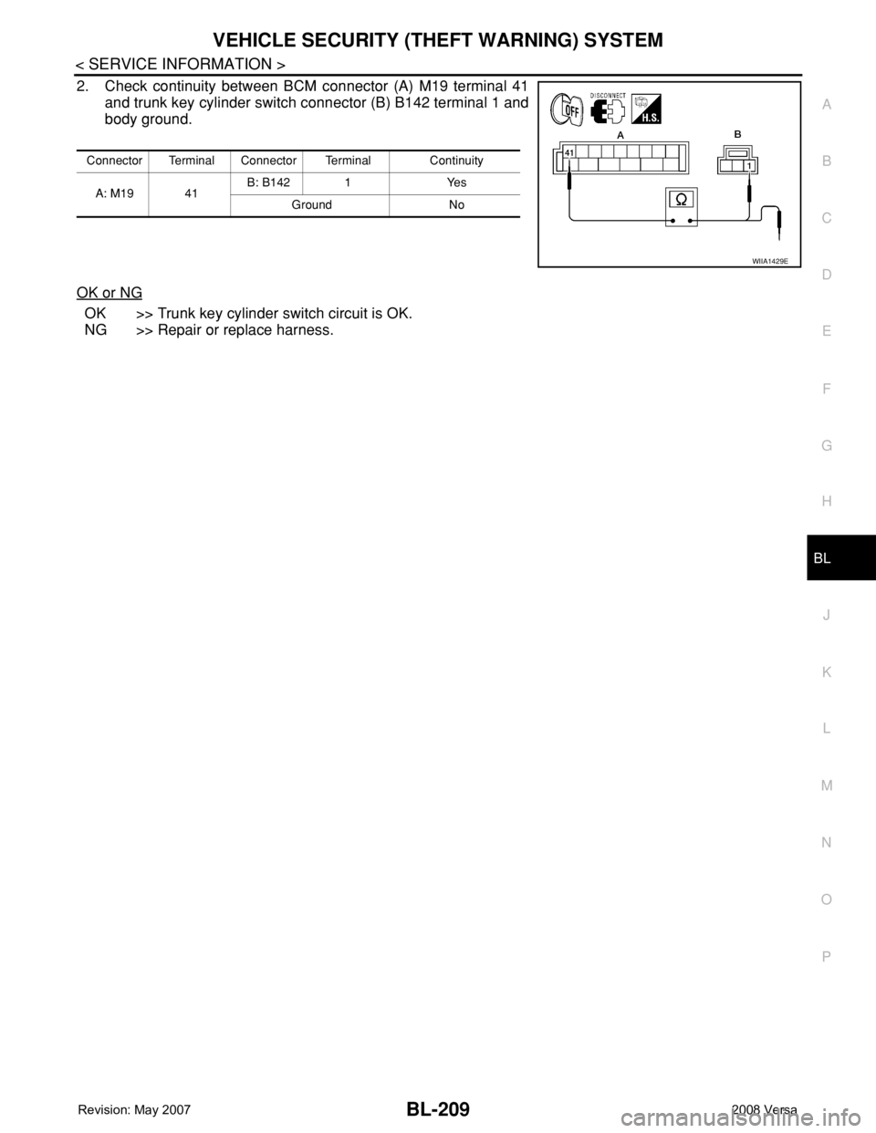
2. Check continuity between BCM connector (A) M19 terminal 41
and trunk key cylinder switch connector (B) B142 terminal 1 and
body ground.
OK or NG
OK >> Trunk key cylinder switch circuit is OK.
NG >> Repair or replace harness.
Connector Terminal Connector Terminal Continuity
A: M19 41B: B142 1 Yes
Ground No
WIIA1429E
Page 666 of 2771

BL-232
< SERVICE INFORMATION >
BODY REPAIR
7. Front roof rail assembly
8. Sun roof assembly
9. Front roof rail assembly (if equipped with sunroof)
10. Roof side rail reinforcement (RH & LH)
11. Inner center pillar (RH & LH)
12. Hood assembly
13. Center pillar reinforcement (RH & LH)
14. Front pillar inner (RH & LH)
15. Front pillar upper reinforcement (RH & LH)
16. Front pillar lower reinforcement (RH & LH)
17. Fender (RH & LH)
18. Side body (RH & LH)
19. Side body assembly (RH & LH)
20. Outer sill (RH & LH)
21. Outer sill reinforcement (RH & LH)
22. Front door assembly (RH & LH)
23. Outer front door panel (RH & LH)
24. Outer rear door panel (RH & LH)
25. Rear door assembly (RH & LH)
26. Rear fender (RH & LH)
27. Rear fender corner (RH & LH)
28. Rear combination lamp base (RH & LH)
29. Rear wheel housing front extension (RH & LH)
30. Rear wheel housing outer (RH & LH)
31. Rear pillar inner reinforcement (RH & LH)
32. Rear body side inner (RH & LH)
33. Rear wheel housing inner (RH & LH)
34. Rear panel assembly
35. Rear bumper fascia upper bracket
36. Rear bumper fascia center bracket
37. Trunk lid assembly
38. Parcel shelf side (RH & LH)
39. Parcel shelf assembly
40. Rear waist panel
41. Rear bumper fascia lower bracket
Corrosion ProtectionINFOID:0000000001704120
DESCRIPTION
To provide improved corrosion prevention, the following anti-corrosive measures have been implemented in
NISSAN production plants. When repairing or replacing body panels, it is necessary to use the same anti-cor-
rosive measures.
ANTI-CORROSIVE PRECOATED STEEL (GALVANNEALED STEEL)