2008 NISSAN LATIO steering wheel
[x] Cancel search: steering wheelPage 1848 of 2771
FSU-14
< SERVICE INFORMATION >
TRANSVERSE LINK
TRANSVERSE LINK
Removal and InstallationINFOID:0000000001703727
REMOVAL
1. Remove front tires using power tool.
2. Remove transverse link ball joint nut and bolt. Then, remove transverse link from steering knuckle.
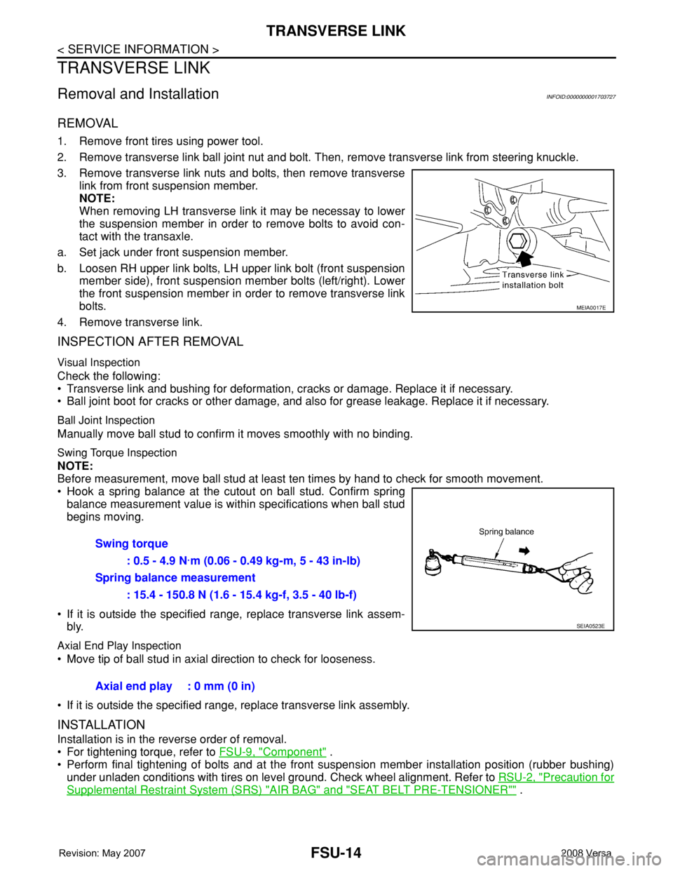
3. Remove transverse link nuts and bolts, then remove transverse
link from front suspension member.
NOTE:
When removing LH transverse link it may be necessay to lower
the suspension member in order to remove bolts to avoid con-
tact with the transaxle.
a. Set jack under front suspension member.
b. Loosen RH upper link bolts, LH upper link bolt (front suspension
member side), front suspension member bolts (left/right). Lower
the front suspension member in order to remove transverse link
bolts.
4. Remove transverse link.
INSPECTION AFTER REMOVAL
Visual Inspection
Check the following:
• Transverse link and bushing for deformation, cracks or damage. Replace it if necessary.
• Ball joint boot for cracks or other damage, and also for grease leakage. Replace it if necessary.
Ball Joint Inspection
Manually move ball stud to confirm it moves smoothly with no binding.
Swing Torque Inspection
NOTE:
Before measurement, move ball stud at least ten times by hand to check for smooth movement.
• Hook a spring balance at the cutout on ball stud. Confirm spring
balance measurement value is within specifications when ball stud
begins moving.
• If it is outside the specified range, replace transverse link assem-
bly.
Axial End Play Inspection
• Move tip of ball stud in axial direction to check for looseness.
• If it is outside the specified range, replace transverse link assembly.
INSTALLATION
Installation is in the reverse order of removal.
• For tightening torque, refer to FSU-9, "
Component" .
• Perform final tightening of bolts and at the front suspension member installation position (rubber bushing)
under unladen conditions with tires on level ground. Check wheel alignment. Refer to RSU-2, "
Precaution for
Supplemental Restraint System (SRS) "AIR BAG" and "SEAT BELT PRE-TENSIONER"" .
MEIA0017E
Swing torque
: 0.5 - 4.9 N·m (0.06 - 0.49 kg-m, 5 - 43 in-lb)
Spring balance measurement
: 15.4 - 150.8 N (1.6 - 15.4 kg-f, 3.5 - 40 lb-f)
SEIA0523E
Axial end play : 0 mm (0 in)
Page 1852 of 2771

GI-1
GENERAL INFORMATION
C
D
E
F
G
H
I
J
K
L
MB
GI
SECTION GI
N
O
P
CONTENTS
GENERAL INFORMATION
SERVICE INFORMATION ............................2
PRECAUTIONS ...................................................2
Description ................................................................2
Precaution for Supplemental Restraint System
(SRS) "AIR BAG" and "SEAT BELT PRE-TEN-
SIONER" ...................................................................
2
Precaution Necessary for Steering Wheel Rota-
tion After Battery Disconnect .....................................
2
General Precaution ...................................................3
Precaution for Three Way Catalyst ...........................4
Precaution for Fuel (Unleaded Regular Gasoline
Recommended) .........................................................
4
Precaution for Multiport Fuel Injection System or
Engine Control System .............................................
5
Precaution for Hoses .................................................5
Precaution for Engine Oils ........................................6
Precaution for Air Conditioning .................................6
HOW TO USE THIS MANUAL ............................7
Description ................................................................7
Terms ........................................................................7
Units ..........................................................................7
Contents ....................................................................7
Relation between Illustrations and Descriptions .......8
Component ................................................................8
How to Follow Trouble Diagnosis ..............................9
How to Read Wiring Diagram ..................................13
Abbreviations ..........................................................20
SERVICE INFORMATION FOR ELECTRICAL
INCIDENT ...........................................................
22
How to Check Terminal ...........................................22
How to Perform Efficient Diagnosis for an Electri-
cal Incident ..............................................................
25
Control Units and Electrical Parts ............................32
CONSULT-III CHECKING SYSTEM .................35
Description ...............................................................35
Function and System Application ............................35
CONSULT-III Data Link Connector (DLC) Circuit ....36
LIFTING POINT .................................................38
Special Service Tool ................................................38
Garage Jack and Safety Stand and 2-Pole Lift .......38
Board-On Lift ...........................................................39
TOW TRUCK TOWING .....................................40
Tow Truck Towing ...................................................40
Vehicle Recovery (Freeing a Stuck Vehicle) ...........40
TIGHTENING TORQUE OF STANDARD
BOLTS ...............................................................
41
Tightening Torque Table .........................................41
RECOMMENDED CHEMICAL PRODUCTS
AND SEALANTS ...............................................
42
Recommended Chemical Product and Sealant .......42
IDENTIFICATION INFORMATION ....................43
Model Variation ........................................................43
Dimensions ..............................................................46
Wheels & Tires ........................................................46
TERMINOLOGY ................................................47
SAE J1930 Terminology List ...................................47
Page 1853 of 2771
GI-2
< SERVICE INFORMATION >
PRECAUTIONS
SERVICE INFORMATION
PRECAUTIONS
DescriptionINFOID:0000000001702421
Observe the following precautions to ensure safe and proper servicing. These precautions are not
described in each individual section.
Precaution for Supplemental Restraint System (SRS) "AIR BAG" and "SEAT BELT
PRE-TENSIONER"
INFOID:0000000001702422
The Supplemental Restraint System such as “AIR BAG” and “SEAT BELT PRE-TENSIONER”, used along
with a front seat belt, helps to reduce the risk or severity of injury to the driver and front passenger for certain
types of collision. Information necessary to service the system safely is included in the SRS and SB section of
this Service Manual.
WARNING:
• To avoid rendering the SRS inoperative, which could increase the risk of personal injury or death in
the event of a collision which would result in air bag inflation, all maintenance must be performed by
an authorized NISSAN/INFINITI dealer.
• Improper maintenance, including incorrect removal and installation of the SRS, can lead to personal
injury caused by unintentional activation of the system. For removal of Spiral Cable and Air Bag
Module, see the SRS section.
• Do not use electrical test equipment on any circuit related to the SRS unless instructed to in this
Service Manual. SRS wiring harnesses can be identified by yellow and/or orange harnesses or har-
ness connectors.
Precaution Necessary for Steering Wheel Rotation After Battery Disconnect
INFOID:0000000001702423
NOTE:
• This Procedure is applied only to models with Intelligent Key system and NATS (NISSAN ANTI-THEFT SYS-
TEM).
• Remove and install all control units after disconnecting both battery cables with the ignition knob in the
″LOCK″ position.
• Always use CONSULT-III to perform self-diagnosis as a part of each function inspection after finishing work.
If DTC is detected, perform trouble diagnosis according to self-diagnostic results.
For models equipped with the Intelligent Key system and NATS, an electrically controlled steering lock mech-
anism is adopted on the key cylinder.
For this reason, if the battery is disconnected or if the battery is discharged, the steering wheel will lock and
steering wheel rotation will become impossible.
If steering wheel rotation is required when battery power is interrupted, follow the procedure below before
starting the repair operation.
OPERATION PROCEDURE
1. Connect both battery cables.
NOTE:
Supply power using jumper cables if battery is discharged.
2. Use the Intelligent Key or mechanical key to turn the ignition switch to the ″ACC″ position. At this time, the
steering lock will be released.
3. Disconnect both battery cables. The steering lock will remain released and the steering wheel can be
rotated.
4. Perform the necessary repair operation.
5. When the repair work is completed, return the ignition switch to the ″LOCK″ position before connecting
the battery cables. (At this time, the steering lock mechanism will engage.)
6. Perform a self-diagnosis check of all control units using CONSULT-III.
Page 1872 of 2771

HOW TO USE THIS MANUAL
GI-21
< SERVICE INFORMATION >
C
D
E
F
G
H
I
J
K
L
MB
GI
N
O
PFR, RR Front, Rear
LH, RH Left-Hand, Right-Hand
M/T Manual Transaxle/Transmission
OD Overdrive
P/S Power Steering
SAE Society of Automotive Engineers, Inc.
SDS Service Data and Specifications
SST Special Service Tools
2WD 2-Wheel Drive
2
22nd range 2nd gear
2
12nd range 1st gear
1
21st range 2nd gear
1
11st range 1st gear ABBREVIATION DESCRIPTION
Page 1891 of 2771
GI-40
< SERVICE INFORMATION >
TOW TRUCK TOWING
TOW TRUCK TOWING
Tow Truck TowingINFOID:0000000001702452
CAUTION:
• All applicable local laws regarding the towing operation must be obeyed.
• It is necessary to use proper towing equipment to avoid possible damage to the vehicle during tow-
ing operation. Towing is in accordance with Towing Procedure Manual at dealer.
• Always attach safety chains before towing.
• When towing, make sure that the transmission, steering system and power train are in good order. If
any unit is damaged, dollies must be used.
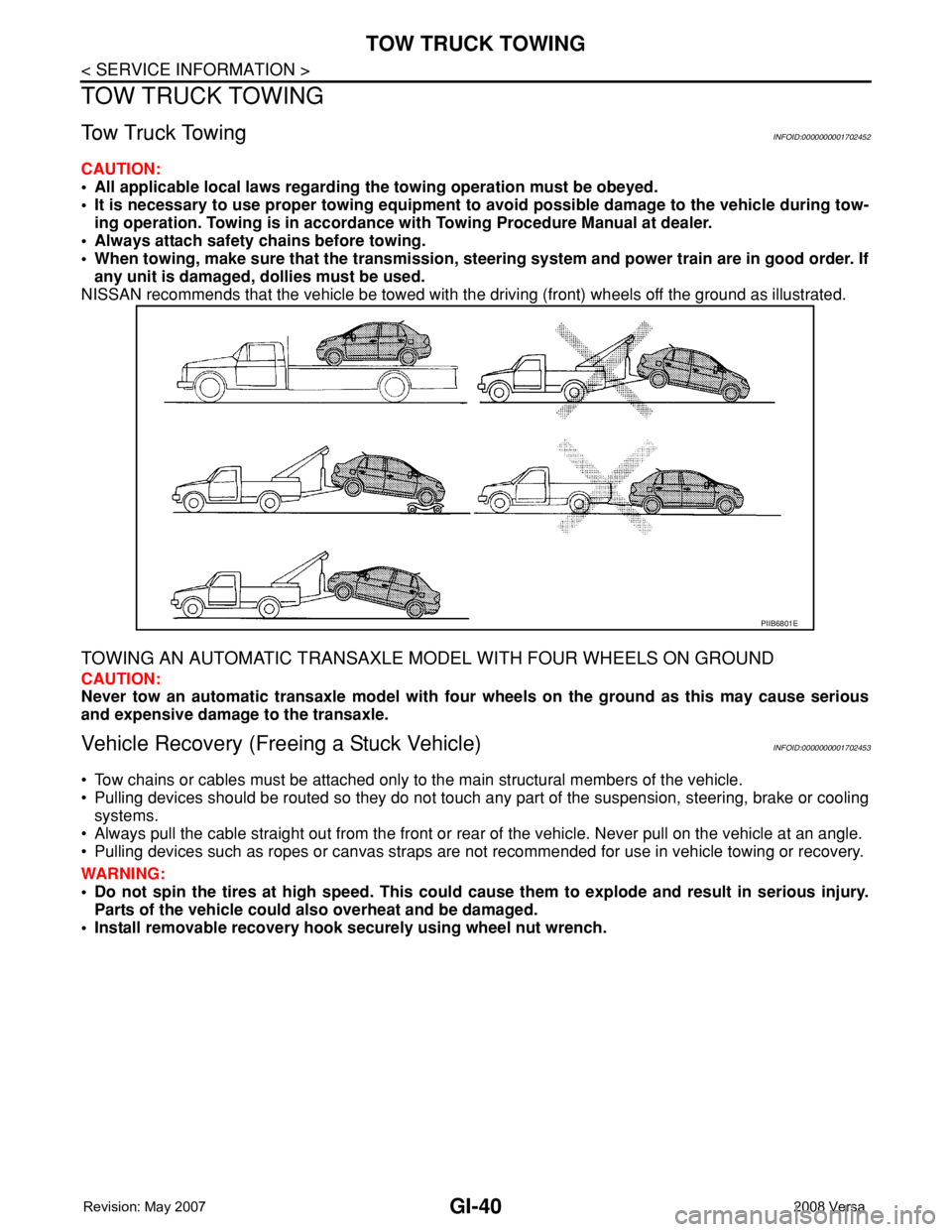
NISSAN recommends that the vehicle be towed with the driving (front) wheels off the ground as illustrated.
TOWING AN AUTOMATIC TRANSAXLE MODEL WITH FOUR WHEELS ON GROUND
CAUTION:
Never tow an automatic transaxle model with four wheels on the ground as this may cause serious
and expensive damage to the transaxle.
Vehicle Recovery (Freeing a Stuck Vehicle)INFOID:0000000001702453
• Tow chains or cables must be attached only to the main structural members of the vehicle.
• Pulling devices should be routed so they do not touch any part of the suspension, steering, brake or cooling
systems.
• Always pull the cable straight out from the front or rear of the vehicle. Never pull on the vehicle at an angle.
• Pulling devices such as ropes or canvas straps are not recommended for use in vehicle towing or recovery.
WARNING:
• Do not spin the tires at high speed. This could cause them to explode and result in serious injury.
Parts of the vehicle could also overheat and be damaged.
• Install removable recovery hook securely using wheel nut wrench.
PIIB6801E
Page 2264 of 2771
MA-4
< SERVICE INFORMATION >
GENERAL MAINTENANCE
GENERAL MAINTENANCE
Explanation of General MaintenanceINFOID:0000000001704720
General MaintenanceINFOID:0000000001704721
General maintenance includes those items which should be checked during the normal day-to-day operation
of the vehicle. They are essential if the vehicle is to continue operating properly. The owners can perform
checks and inspections themselves or they can have their NISSAN dealers do them.
OUTSIDE THE VEHICLE
The maintenance items listed here should be performed from time to time, unless otherwise specified.
INSIDE THE VEHICLE
The maintenance items listed here should be checked on a regular basis, such as when performing periodic maintenance, cleaning the vehicle,
etc.
ItemReference page
TiresCheck the pressure including the spare, at least once a month and always prior
to a long distance trip. Adjust to the specified pressure if necessary. Check care-
fully for damage, cuts or excessive wear.WT-25, "
Tire"
Wheel nutsWhen checking the tires, make sure no nuts are missing, and check for any loose
nuts. Tighten if necessary.WT-6, "Rotation"
WindshieldClean the windshield on a regular basis. Check the windshield at least every six
months for cracks or other damage. Repair as necessary.—
Tire rotationTires should be rotated every 12,000 km (7,500 miles).WT-6, "
Rotation"
Transmitter compo-
nents in tire pressure
monitoring systemReplace grommet seal, valve core and cap of the transmitter in TPMS every tire
replacement by reaching wear limit of tire.WT-7
Wheel alignment and
balanceIf the vehicle pulls to either side while driving on a straight and level road, or if
you detect uneven or abnormal tire wear, there may be a need for wheel align-
ment. If the steering wheel or seat vibrates at normal highway speeds, wheel bal-
ancing may be needed.FSU-6, "Wheel Align-
ment Inspection" and
WT-6, "
Balancing
Wheels"
Windshield wiper
bladesCheck for cracks or wear if they do not wipe properly. —
Doors and engine
hoodCheck that all doors and the engine hood operate smoothly as well as the trunk
lid and back hatch. Also make sure that all latches lock securely. Lubricate if nec-
essary. Make sure that the secondary latch keeps the hood from opening when
the primary latch is released.
When driving in areas using road salt or other corrosive materials, check lubrica-
tion frequently.MA-27, "
Lubricating
Locks, Hinges and Hood
Latch"
LampsMake sure that the headlamps, stop lamps, tail lamps, turn signal lamps, and oth-
er lamps are all operating properly and installed securely. Also check headlamp
aim. Clean the headlamps on a regular basis.—
ItemReference page
Warning lamps and
buzzers/chimesMake sure that all warning lamps and buzzers/chimes are operating properly. —
Windshield wiper and
washerCheck that the wipers and washer operate properly and that the wipers do not
streak.—
Windshield defrosterCheck that the air comes out of the defroster outlets properly and in sufficient
quantity when operating the heater or air conditioning.—
Steering wheelCheck that it has the specified play. Be sure to check for changes in the steering
condition, such as excessive play, hard steering or strange noises.
Free play: Less than 35 mm (1.38 in)—
SeatsCheck seat position controls such as seat adjusters, seat back recliner, etc. to
make sure they operate smoothly and that all latches lock securely in every po-
sition. Check that the head restraints move up and down smoothly and that the
locks (if equipped) hold securely in all latched positions. Check that the latches
lock securely for folding-down rear seat backs.—
Page 2507 of 2771

PS-1
STEERING
C
D
E
F
H
I
J
K
L
M
SECTION PS
A
B
PS
N
O
P
CONTENTS
POWER STEERING SYSTEM
SERVICE INFORMATION ............................2
PRECAUTIONS ...................................................2
Precaution for Supplemental Restraint System
(SRS) "AIR BAG" and "SEAT BELT PRE-TEN-
SIONER" ...................................................................
2
Precaution Necessary for Steering Wheel Rota-
tion After Battery Disconnect .....................................
2
Precaution for Steering System ................................2
PREPARATION ...................................................4
Special Service Tool .................................................4
Commercial Service Tool ..........................................4
NOISE, VIBRATION AND HARSHNESS
(NVH) TROUBLESHOOTING .............................
5
NVH Troubleshooting Chart ......................................5
STEERING WHEEL ...........................................6
On-Vehicle Inspection and Service ..........................6
Removal and Installation ..........................................7
STEERING COLUMN .........................................9
Removal and Installation ..........................................9
POWER STEERING GEAR ..............................12
Removal and Installation .........................................12
Disassembly and Assembly .....................................13
SERVICE DATA AND SPECIFICATIONS
(SDS) .................................................................
17
Steering Wheel ........................................................17
Steering Angle .........................................................17
Steering Column ......................................................17
Steering Outer Socket and Inner Socket .................17
Steering Gear ..........................................................18
Page 2508 of 2771
PS-2
< SERVICE INFORMATION >
PRECAUTIONS
SERVICE INFORMATION
PRECAUTIONS
Precaution for Supplemental Restraint System (SRS) "AIR BAG" and "SEAT BELT
PRE-TENSIONER"
INFOID:0000000001703853
The Supplemental Restraint System such as “AIR BAG” and “SEAT BELT PRE-TENSIONER”, used along
with a front seat belt, helps to reduce the risk or severity of injury to the driver and front passenger for certain
types of collision. This system includes seat belt switch inputs and dual stage front air bag modules. The SRS
system uses the seat belt switches to determine the front air bag deployment, and may only deploy one front
air bag, depending on the severity of a collision and whether the front occupants are belted or unbelted.
Information necessary to service the system safely is included in the SRS and SB section of this Service Man-
ual.
WARNING:
• To avoid rendering the SRS inoperative, which could increase the risk of personal injury or death in
the event of a collision which would result in air bag inflation, all maintenance must be performed by
an authorized NISSAN/INFINITI dealer.
• Improper maintenance, including incorrect removal and installation of the SRS, can lead to personal
injury caused by unintentional activation of the system. For removal of Spiral Cable and Air Bag
Module, see the SRS section.
• Do not use electrical test equipment on any circuit related to the SRS unless instructed to in this
Service Manual. SRS wiring harnesses can be identified by yellow and/or orange harnesses or har-
ness connectors.
Precaution Necessary for Steering Wheel Rotation After Battery Disconnect
INFOID:0000000001703854
NOTE:
• This procedure is applied only to models with Intelligent Key system and NATS (NISSAN ANTI-THEFT SYS-
TEM).
• Remove and install all control units after disconnecting both battery cables with the ignition switch in the
″LOCK″ position.
• Always use CONSULT-II to perform self-diagnosis as a part of each function inspection after finishing work.
If DTC is detected, perform trouble diagnosis according to self-diagnostic results.
For models equipped with the Intelligent Key system and NATS, an electrically controlled steering lock mech-
anism is adopted on the key cylinder.
For this reason, if the battery is disconnected or if the battery is discharged, the steering wheel will lock and
steering wheel rotation will become impossible.
If steering wheel rotation is required when battery power is interrupted, follow the procedure below before
starting the repair operation.
OPERATION PROCEDURE
1. Connect both battery cables.
NOTE:
Supply power using jumper cables if battery is discharged.
2. Use the Intelligent Key or mechanical key to turn the ignition switch to the ″ACC″ position. At this time, the
steering lock will be released.
3. Disconnect both battery cables. The steering lock will remain released and the steering wheel can be
rotated.
4. Perform the necessary repair operation.
5. When the repair work is completed, return the ignition switch to the ″LOCK″ position before connecting
the battery cables. (At this time, the steering lock mechanism will engage.)
6. Perform a self-diagnosis check of all control units using CONSULT-II.
Precaution for Steering SystemINFOID:0000000001703855
• In case of removing steering gear assembly, make the final tightening with grounded and unloaded vehicle
condition, and then check wheel alignment.
• Observe the following precautions when disassembling.