2008 NISSAN LATIO diagram
[x] Cancel search: diagramPage 404 of 2771
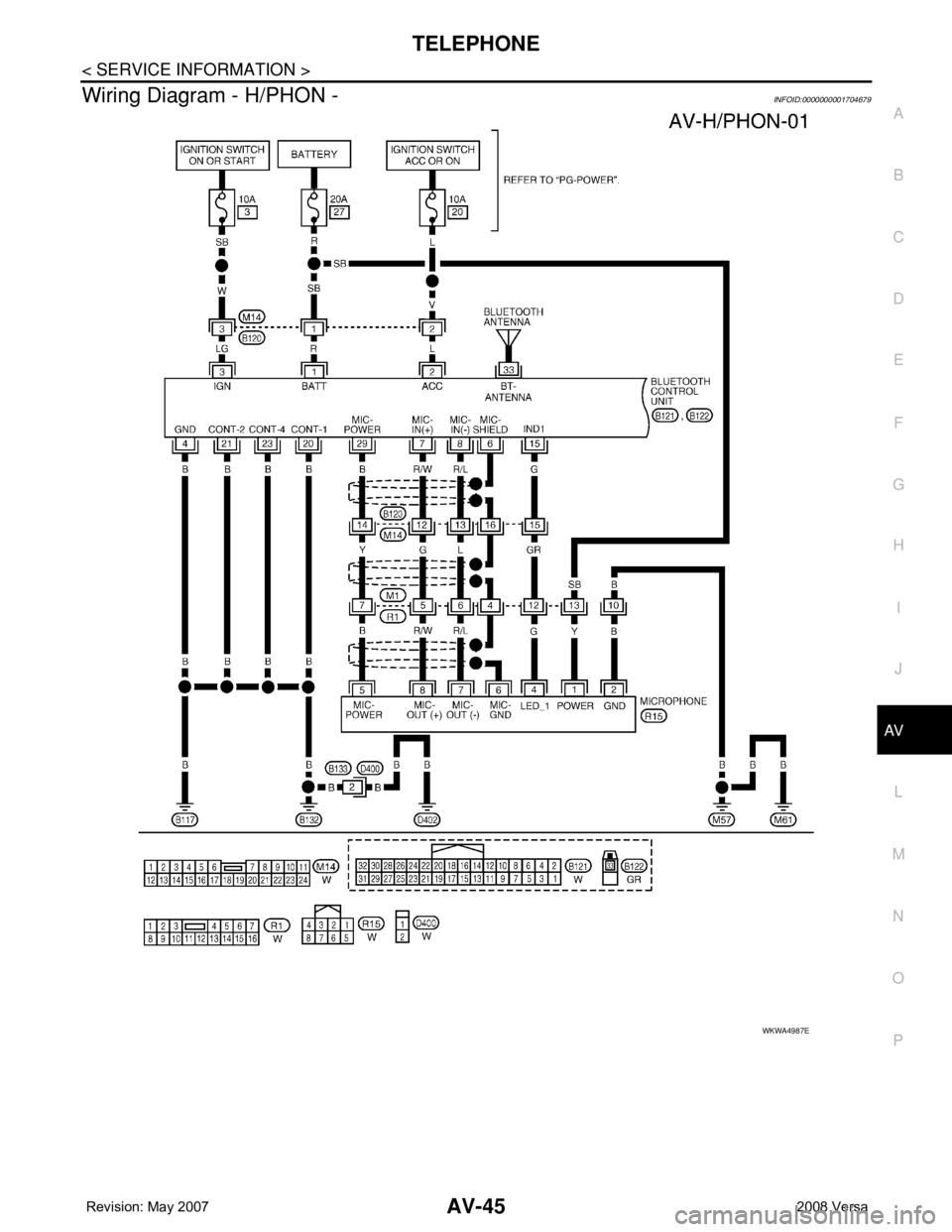
TELEPHONE
AV-45
< SERVICE INFORMATION >
C
D
E
F
G
H
I
J
L
MA
B
AV
N
O
P
Wiring Diagram - H/PHON -INFOID:0000000001704679
WKWA4987E
Page 435 of 2771

BL-1
BODY
C
D
E
F
G
H
J
K
L
M
SECTION BL
A
B
BL
N
O
P
CONTENTS
BODY, LOCK & SECURITY SYSTEM
SERVICE INFORMATION ............................4
PRECAUTIONS ...................................................4
Precaution for Supplemental Restraint System
(SRS) "AIR BAG" and "SEAT BELT PRE-TEN-
SIONER" ...................................................................
4
Precaution Necessary for Steering Wheel Rota-
tion After Battery Disconnect .....................................
4
Precaution for Procedure without Cowl Top Cover ......5
Precaution for Work ..................................................5
PREPARATION ...................................................6
Special Service Tool .................................................6
Commercial Service Tool ..........................................6
SQUEAK AND RATTLE TROUBLE DIAG-
NOSES ................................................................
7
Work Flow .................................................................7
Generic Squeak and Rattle Troubleshooting ............9
Diagnostic Worksheet .............................................11
HOOD .................................................................13
Fitting Adjustment ...................................................13
Removal and Installation .........................................14
Removal and Installation of Hood Lock Control ......15
Hood Lock Control Inspection .................................17
RADIATOR CORE SUPPORT ...........................19
Removal and Installation .........................................19
FRONT FENDER ................................................21
Removal and Installation .........................................21
POWER DOOR LOCK SYSTEM ........................22
Component Parts and Harness Connector Loca-
tion ..........................................................................
22
System Description .................................................22
CAN Communication System Description ...............24
Schematic ...............................................................25
Wiring Diagram - D/LOCK - .....................................26
Schematic ...............................................................30
Wiring Diagram - D/LOCK - .....................................31
Terminal and Reference Value for BCM ..................35
Work Flow ................................................................35
CONSULT-III Function (BCM) .................................36
Trouble Diagnosis Symptom Chart ..........................37
BCM Power Supply and Ground Circuit ..................37
Door Switch Check (Hatchback) ..............................37
Door Switch Check (Sedan) ....................................40
Key Switch (Insert) Check .......................................41
Door Lock and Unlock Switch Check ......................42
Front Door Lock Assembly LH (Actuator) Check .....45
Door Lock Actuator Check (Front RH and Rear
LH/RH) .....................................................................
46
Front Door Key Cylinder Switch LH Check ..............47
Passenger Select Unlock Relay Circuit Inspection
(With Intelligent Key) ...............................................
48
REMOTE KEYLESS ENTRY SYSTEM .............51
Component Parts and Harness Connector Loca-
tion ...........................................................................
51
System Description ..................................................51
CAN Communication System Description ...............53
Schematic ................................................................54
Wiring Diagram - KEYLES - ....................................55
Terminal and Reference Value for BCM ..................57
How to Perform Trouble Diagnosis ..........................57
Preliminary Check ...................................................58
CONSULT-III Function (BCM) .................................58
Work Flow ................................................................59
Trouble Diagnosis Symptom Chart ..........................60
Keyfob Battery and Function Check ........................61
ACC Switch Check ..................................................62
Door Switch Check (Hatchback) ..............................62
Door Switch Check (Sedan) ....................................65
Key Switch (Insert) Check .......................................66
Hazard Function Check ...........................................67
Horn Function Check ...............................................67
Interior Lamp and Ignition Keyhole Illumination
Function Check ........................................................
68
Remote Keyless Entry Receiver Check ...................68
Keyfob Function (Lock) Check ................................71
Keyfob Function (Unlock) Check .............................71
Page 436 of 2771

BL-2
ID Code Entry Procedure .......................................71
Keyfob Battery Replacement ..................................73
Removal and Installation of Remote Keyless Entry
Receiver .................................................................
73
INTELLIGENT KEY SYSTEM ............................74
Component Parts and Harness Connector Loca-
tion ..........................................................................
74
System Description .................................................76
CAN Communication System Description ..............83
Schematic ...............................................................84
Wiring Diagram - I/KEY - ........................................86
Intelligent Key Unit Harness Connector Terminal
Layout .....................................................................
96
Terminal and Reference Value for Intelligent Key
Unit .........................................................................
96
Steering Lock Solenoid Harness Connector Ter-
minal Layout ...........................................................
98
Terminal and Reference Value for Steering Lock
Solenoid ..................................................................
98
Terminal and Reference Value for BCM .................99
Trouble Diagnosis Procedure .................................99
CONSULT-III Functions (INTELLIGENT KEY) ......100
CONSULT-III Application Item ...............................101
Trouble Diagnosis Symptom Chart ........................103
CAN Communication System Inspection ...............109
Power Supply and Ground Circuit Inspection ........110
Key Switch (Intelligent Key Unit Input) Check .......110
Key Switch (BCM Input) Check .............................112
Ignition Knob Switch Check ...................................113
Door Switch Check (Hatchback) ............................114
Door Switch Check (Sedan) ..................................117
Door Request Switch Check ..................................118
Back Door Request Switch Check (Hatchback) ....120
Trunk Opener Request Switch Check (Sedan) .....122
Unlock Sensor Check ............................................124
Intelligent Key Warning Buzzer(s) Check ..............125
Outside Key Antenna (Driver Side and Passenger
Side) Check ...........................................................
126
Outside Key Antenna (Rear Bumper) Check .........128
Inside Key Antenna Check ....................................129
Steering Lock Solenoid Check ..............................131
Key Interlock Solenoid (With M/T) Check ..............133
Ignition Switch Position Check ..............................134
Stop Lamp Switch Check (With CVT) ....................134
Stop Lamp Switch Check (With M/T) .....................135
Check CVT Device (Park Position Switch) Check ..136
"P-SHIFT" Warning Lamp (With CVT) Check ........138
"LOCK" Warning Lamp (With M/T) Check .............138
"KEY" Warning Lamp (RED) Check ......................139
"KEY" Warning Lamp (GREEN) Check .................139
Check Warning Chime in Combination Meter ........140
Hazard Function Check .........................................140
Horn Function Check .............................................140
Headlamp Function Check ....................................141
Intelligent Key Battery Replacement .....................142
Remote Keyless Entry Function ............................142
Removal and Installation of Intelligent Key Unit ....142
DOOR ...............................................................144
Fitting Adjustment .................................................144
Removal and Installation .......................................147
FRONT DOOR LOCK .......................................150
Component Parts Location ...................................150
Removal and Installation .......................................150
REAR DOOR LOCK .........................................153
Component Parts Location ...................................153
Removal and Installation .......................................153
BACK DOOR LOCK .........................................156
Component Parts and Harness Connector Loca-
tion ........................................................................
156
System Description ...............................................156
Wiring Diagram - B/DOOR - ..................................157
Terminal and Reference Value for BCM ...............158
Terminal and Reference Value for Intelligent Key
Unit ........................................................................
158
CONSULT-III Function (BCM) ..............................159
Work Flow .............................................................159
Trouble Diagnosis Chart by Symptom ..................159
BCM Power Supply and Ground Circuit ................160
Check Back Door Opener Switch Circuit (Without
Intelligent Key or Power Windows) .......................
160
Check Back Door Opener Switch Circuit (Without
Intelligent Key, with Power Windows) ...................
162
Check Back Door Opener Switch Circuit (With In-
telligent Key) .........................................................
165
Check Back Door Lock Assembly (Actuator) Cir-
cuit ........................................................................
166
Removal and Installation .......................................168
TRUNK LID .......................................................170
Fitting Adjustment .................................................170
Trunk Lid Assembly ..............................................170
Trunk Lid Lock ......................................................171
Trunk Lid Striker ....................................................171
TRUNK LID OPENER .......................................173
Component Parts and Harness Connector Loca-
tion ........................................................................
173
System Description ...............................................173
Wiring Diagram - TLID - ........................................174
Terminal and Reference Value for BCM ...............175
Terminal and Reference Value for Intelligent Key
Unit ........................................................................
175
CONSULT-III Function (BCM) ..............................176
Work Flow .............................................................176
Trouble Diagnosis Chart by Symptom ..................176
BCM Power Supply and Ground Circuit ................177
Check Trunk Lid Opener Switch Circuit (Without
Intelligent Key or Power Windows) .......................
177
Check Trunk Lid Opener Switch Circuit (Without
Intelligent Key, with Power Windows) ...................
179
Check Trunk Lid Opener Switch Circuit (With Intel-
ligent Key) .............................................................
182
Check Trunk Release Solenoid Circuit .................183
Page 437 of 2771

BL-3
C
D
E
F
G
H
J
K
L
MA
B
BL
N
O
P
FUEL FILLER LID OPENER ............................186
Removal and Installation of Fuel Filler Lid Opener ..186
VEHICLE SECURITY (THEFT WARNING)
SYSTEM ...........................................................
187
Component Parts and Harness Connector Loca-
tion ........................................................................
187
System Description ...............................................188
CAN Communication System Description .............190
Schematic .............................................................191
Wiring Diagram - VEHSEC - .................................192
Terminal and Reference Value for BCM ...............195
Terminal and Reference Value for Intelligent Key
Unit ........................................................................
195
CONSULT-III Function (BCM) ...............................196
Trouble Diagnosis .................................................197
Preliminary Check .................................................197
Symptom Chart .....................................................199
Diagnosis Procedure 1 ..........................................200
Diagnosis Procedure 2 ..........................................203
Diagnosis Procedure 3 ..........................................204
Diagnosis Procedure 4 ..........................................204
Diagnosis Procedure 5 ..........................................204
Diagnosis Procedure 6 ..........................................204
Diagnosis Procedure 7 ..........................................204
Diagnosis Procedure 8 ..........................................206
Diagnosis Procedure 9 ..........................................207
NATS (Nissan Anti-Theft System) .................210
Component Parts and Harness Connector Loca-
tion .........................................................................
210
System Description ................................................210
System Composition ..............................................211
ECM Re-communicating Function .........................211
Wiring Diagram - NATS - .......................................213
Terminal and Reference Value for BCM ................213
CONSULT-III Function ..........................................213
Trouble Diagnosis Procedure ................................215
Trouble Diagnosis ..................................................217
Diagnosis Procedure 1 ..........................................218
Diagnosis Procedure 2 ..........................................220
Diagnosis Procedure 3 ..........................................221
Diagnosis Procedure 4 ..........................................222
Diagnosis Procedure 5 ..........................................223
How to Replace NATS Antenna Amp ....................224
BODY REPAIR ................................................225
Body Exterior Paint Color ......................................225
Body Component Parts .........................................227
Corrosion Protection ..............................................232
Body Sealing .........................................................236
Body Construction .................................................242
Body Alignment .....................................................244
Handling Precaution for Plastics ............................261
Precaution in Repairing High Strength Steel .........265
Foam Repair ..........................................................268
Replacement Operation .........................................271
Page 460 of 2771
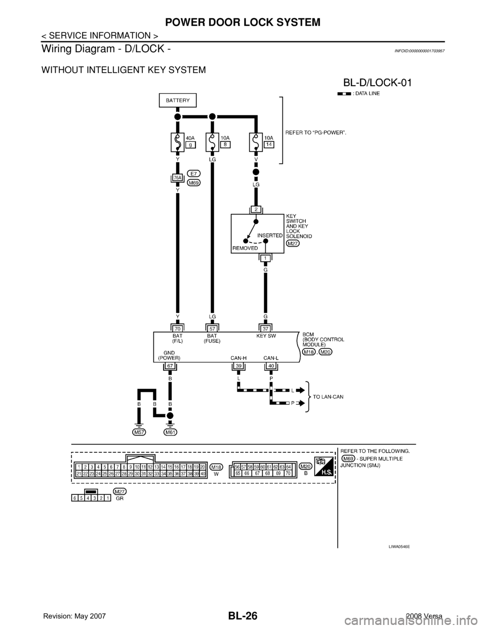
BL-26
< SERVICE INFORMATION >
POWER DOOR LOCK SYSTEM
Wiring Diagram - D/LOCK -
INFOID:0000000001703957
WITHOUT INTELLIGENT KEY SYSTEM
LIWA0546E
Page 465 of 2771
POWER DOOR LOCK SYSTEM
BL-31
< SERVICE INFORMATION >
C
D
E
F
G
H
J
K
L
MA
B
BL
N
O
P
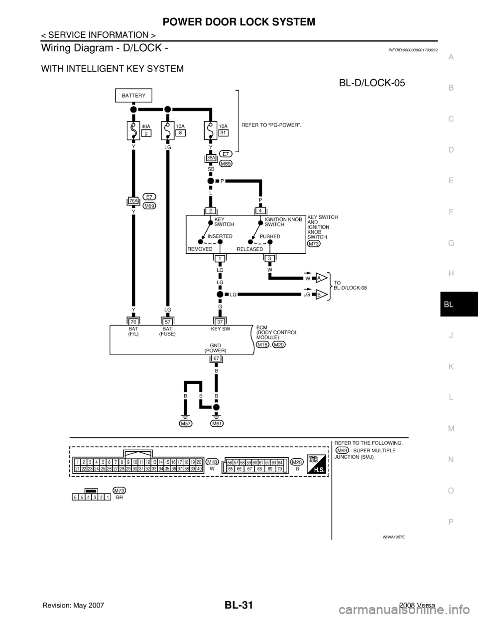
Wiring Diagram - D/LOCK -INFOID:0000000001703959
WITH INTELLIGENT KEY SYSTEM
WIWA1957E
Page 489 of 2771
REMOTE KEYLESS ENTRY SYSTEM
BL-55
< SERVICE INFORMATION >
C
D
E
F
G
H
J
K
L
MA
B
BL
N
O
P
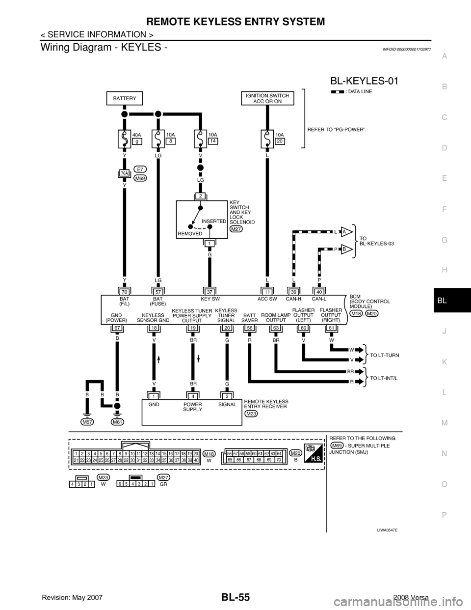
Wiring Diagram - KEYLES -INFOID:0000000001703977
LIWA0547E
Page 510 of 2771
BL-76
< SERVICE INFORMATION >
INTELLIGENT KEY SYSTEM
System Description
INFOID:0000000001703999
• The Intelligent Key system is a system that makes it possible to lock and unlock the door locks (door lock/
unlock function), and start the engine (engine start function) by carrying around the Intelligent Key (without
some key operation), which operates based on the results of electronic ID verification using two-way com-
munications between the Intelligent Key and the vehicle (Intelligent Key unit).
• Vehicles equipped with a manual transmission include a key interlock solenoid located in the steering col-
umn to prevent accidental shut-off of the ignition switch and locking of the steering wheel during driving con-
dition when the vehicle is moving.
CAUTION:
The driver should always carry the Intelligent Key
• Operation of the remote controller buttons on the Intelligent Key also provides the same functions as the
remote control entry system. (Remote keyless entry functions)
• If an action that does not meet the operating conditions of the Intelligent Key system is taken, the buzzer
goes off to inform the driver. (Warning chime functions)
• When a door lock is locked or unlocked with request switch or remote controller button operation, the hazard
lamps flash and the buzzer (outside vehicle) sounds (Hazard and buzzer reminder function).
• Even if the Intelligent Key battery is completely discharged, the door locks can be locked and unlocked and
the engine started with the mechanical key built into the Intelligent Key.
• The settings for each function can be changed with the CONSULT-III.
• If an Intelligent Key is lost, a new Intelligent Key can be registered. A maximum of 4 Intelligent Keys can be
registered.
• It has been made possible to diagnose the system and register an Intelligent Key with the CONSULT-III.
DOOR LOCK/UNLOCK FUNCTION
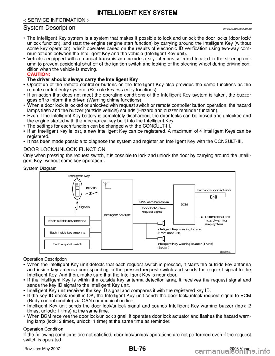
Only when pressing the request switch, it is possible to lock and unlock the door by carrying around the Intelli-
gent Key (without some key operation).
System Diagram
Operation Description
• When the Intelligent Key unit detects that each request switch is pressed, it starts the outside key antenna
and inside key antenna corresponding to the pressed request switch and sends the request signal to the
Intelligent Key. And then, make sure that the Intelligent Key is near door.
• If the Intelligent Key is within the outside key antenna detection area, it receives the request signal and
sends the key ID signal to the Intelligent Key unit.
• Intelligent Key unit receives the key ID signal and compares it with the registered key ID.
• If the key ID check result is OK, the Intelligent Key unit sends the door lock/unlock request signal to BCM
(Body control module) via CAN communication line.
• Intelligent Key unit sends the door lock/unlock signal and sounds Intelligent Key warning buzzer (lock: 2
times, unlock: 1 time) at the same time.
• When BCM receives the door lock/unlock signal, it operates door lock actuator and flashes the hazard warn-
ing lamp (lock: 2 times, unlock: 1 time) at the same time as reminder.
Operation Condition
If the following conditions are not satisfied, door lock/unlock operations are not performed even if the request
switch is operated.
LIIA2926E