Page 1616 of 2771
EC-542
< SERVICE INFORMATION >
REFRIGERANT PRESSURE SENSOR
Wiring Diagram
INFOID:0000000001703077
Specification data are reference values and are measured between each terminal and ground.
CAUTION:
Do not use ECM ground terminals when measuring input/output voltage. Doing so may result in dam-
age to the ECM's transistor. Use a ground other than ECM terminals, such as the ground.
BBWA2662E
Page 1617 of 2771

REFRIGERANT PRESSURE SENSOR
EC-543
< SERVICE INFORMATION >
C
D
E
F
G
H
I
J
K
L
MA
EC
N
P O
Diagnosis ProcedureINFOID:0000000001703078
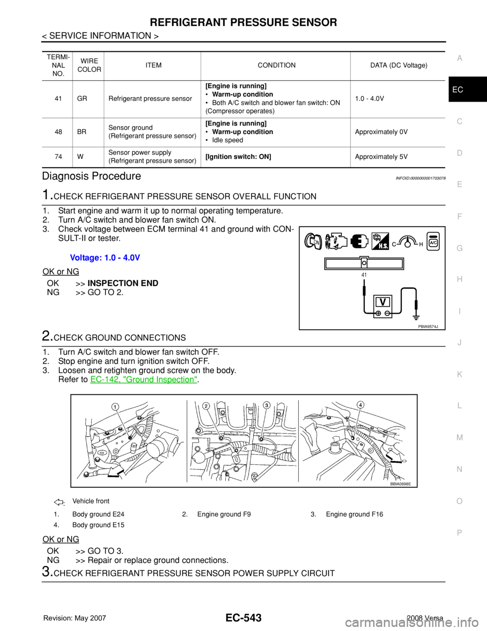
1.CHECK REFRIGERANT PRESSURE SENSOR OVERALL FUNCTION
1. Start engine and warm it up to normal operating temperature.
2. Turn A/C switch and blower fan switch ON.
3. Check voltage between ECM terminal 41 and ground with CON-
SULT-II or tester.
OK or NG
OK >>INSPECTION END
NG >> GO TO 2.
2.CHECK GROUND CONNECTIONS
1. Turn A/C switch and blower fan switch OFF.
2. Stop engine and turn ignition switch OFF.
3. Loosen and retighten ground screw on the body.
Refer to EC-142, "
Ground Inspection".
OK or NG
OK >> GO TO 3.
NG >> Repair or replace ground connections.
3.CHECK REFRIGERANT PRESSURE SENSOR POWER SUPPLY CIRCUIT
TERMI-
NAL
NO.WIRE
COLORITEM CONDITION DATA (DC Voltage)
41 GR Refrigerant pressure sensor[Engine is running]
•Warm-up condition
• Both A/C switch and blower fan switch: ON
(Compressor operates)1.0 - 4.0V
48 BRSensor ground
(Refrigerant pressure sensor)[Engine is running]
•Warm-up condition
• Idle speedApproximately 0V
74 WSensor power supply
(Refrigerant pressure sensor)[Ignition switch: ON]Approximately 5V
Voltage: 1.0 - 4.0V
PBIA9574J
:Vehicle front
1. Body ground E24 2. Engine ground F9 3. Engine ground F16
4. Body ground E15
BBIA0698E
Page 1618 of 2771

EC-544
< SERVICE INFORMATION >
REFRIGERANT PRESSURE SENSOR
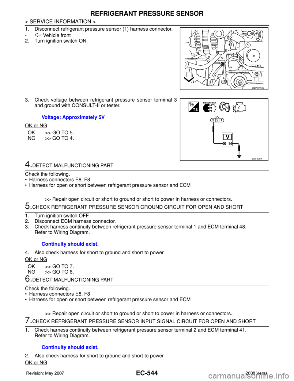
1. Disconnect refrigerant pressure sensor (1) harness connector.
- : Vehicle front
2. Turn ignition switch ON.
3. Check voltage between refrigerant pressure sensor terminal 3
and ground with CONSULT-II or tester.
OK or NG
OK >> GO TO 5.
NG >> GO TO 4.
4.DETECT MALFUNCTIONING PART
Check the following.
• Harness connectors E8, F8
• Harness for open or short between refrigerant pressure sensor and ECM
>> Repair open circuit or short to ground or short to power in harness or connectors.
5.CHECK REFRIGERANT PRESSURE SENSOR GROUND CIRCUIT FOR OPEN AND SHORT
1. Turn ignition switch OFF.
2. Disconnect ECM harness connector.
3. Check harness continuity between refrigerant pressure sensor terminal 1 and ECM terminal 48.
Refer to Wiring Diagram.
4. Also check harness for short to ground and short to power.
OK or NG
OK >> GO TO 7.
NG >> GO TO 6.
6.DETECT MALFUNCTIONING PART
Check the following.
• Harness connectors E8, F8
• Harness for open or short between refrigerant pressure sensor and ECM
>> Repair open circuit or short to ground or short to power in harness or connectors.
7.CHECK REFRIGERANT PRESSURE SENSOR INPUT SIGNAL CIRCUIT FOR OPEN AND SHORT
1. Check harness continuity between refrigerant pressure sensor terminal 2 and ECM terminal 41.
Refer to Wiring Diagram.
2. Also check harness for short to ground and short to power.
OK or NG
BBIA0713E
Voltage: Approximately 5V
SEF479Y
Continuity should exist.
Continuity should exist.
Page 1619 of 2771
REFRIGERANT PRESSURE SENSOR
EC-545
< SERVICE INFORMATION >
C
D
E
F
G
H
I
J
K
L
MA
EC
N
P O
OK >> GO TO 9.
NG >> GO TO 8.
8.DETECT MALFUNCTIONING PART
Check the following.
• Harness connectors E8, F8
• Harness for open or short between refrigerant pressure sensor and ECM
>> Repair open circuit or short to ground or short to power in harness or connectors.
9.CHECK INTERMITTENT INCIDENT
Refer to EC-136
.
OK or NG
OK >> Replace refrigerant pressure sensor.
NG >> Repair or replace.
Removal and InstallationINFOID:0000000001703079
REFRIGERANT PRESSURE SENSOR
Refer to MTC-81, "Removal and Installation of Refrigerant Pressure Sensor".
Page 1622 of 2771

EC-548
< SERVICE INFORMATION >
SERVICE DATA AND SPECIFICATIONS (SDS)
SERVICE DATA AND SPECIFICATIONS (SDS)
Fuel PressureINFOID:0000000001703081
Idle Speed and Ignition TimingINFOID:0000000001703082
*: Under the following conditions:
• Air conditioner switch: OFF
• Electric load: OFF (Lights, heater fan & rear window defogger)
• Steering wheel: Kept in straight-ahead position
Calculated Load ValueINFOID:0000000001703083
Mass Air Flow SensorINFOID:0000000001703084
*: Engine is warmed up to normal operating temperature and running under no load.
Intake Air Temperature SensorINFOID:0000000001703085
Engine Coolant Temperature SensorINFOID:0000000001703086
Fuel pressure at idle
Approximately 350 kPa (3.57 kg/cm2, 51 psi)
Target idle speedA/T No load* (in P or N position)
700 ± 50 rpm CVT No load* (In P or N position)
M/T No load* (in Neutral position)
Air conditioner: ONA/T In P or N position
850 rpm or more CVT In P or N position
M/T In Neutral position
Ignition timingA/T In P or N position
13 ± 5° BTDC CVT In P or N position
M/T In Neutral position
Calculated load value% (Using CONSULT-II or GST)
At idle10 - 35
At 2,500 rpm10 - 35
Supply voltageBattery voltage (11 - 14V)
Output voltage at idle1.0 - 1.3*V
Mass air flow (Using CONSULT-II or GST)1.0 - 4.0 g·m/sec at idle*
2.0 - 10.0 g·m/sec at 2,500 rpm*
Temperature °C (°F) Resistance kΩ
25 (77)1.800 - 2.200
Temperature °C (°F) Resistance kΩ
20 (68)2.1 - 2.9
50 (122)0.68 - 1.00
90 (194)0.236 - 0.260
Page 1623 of 2771
SERVICE DATA AND SPECIFICATIONS (SDS)
EC-549
< SERVICE INFORMATION >
C
D
E
F
G
H
I
J
K
L
MA
EC
N
P O
Air Fuel Ratio (A/F) Sensor 1 HeaterINFOID:0000000001703087
Heated Oxygen sensor 2 HeaterINFOID:0000000001703088
Crankshaft Position Sensor (POS)INFOID:0000000001703089
Refer to EC-301, "Component Inspection".
Camshaft Position Sensor (PHASE)INFOID:0000000001703090
Refer to EC-307, "Component Inspection".
Throttle Control MotorINFOID:0000000001703091
Fuel InjectorINFOID:0000000001703092
Fuel PumpINFOID:0000000001703093
Resistance [at 25°C (77°F)] 1.8 - 2.44Ω
Resistance [at 25°C (77°F)] 3.4 - 4.4Ω
Resistance [at 25°C (77°F)] Approximately 1 - 15Ω
Resistance [at 10 - 60°C (50 - 140°F)] 11.4 - 14.5Ω
Resistance [at 25°C (77°F)] Approximately 0.2 - 5.0Ω
Page 1667 of 2771
EI-44
< ON-VEHICLE REPAIR >
FLOOR TRIM
6. Disconnect floor harness connector.
7. Remove diagnosis sensor unit. Refer to SRS-44
.
8. Remove key interlock cable. Refer to AT-213
.
9. Remove floor carpet hook.
10. Cut floor trim using a blade knife first between openings (1),
then at front edge (2) as shown.
11. Release floor trim metal clips after cutting, then pull out floor trim through door opening.
12. Remove floor spacer RH/LH.
INSTALLATION
Installation is in the reverse order of removal.
CAUTION:
When replacing the floor trim with a new one, prepare for installation by cutting it like the old one.
Make sure there is a quality fit between floor trim and instrument lower cover by tucking the cut edge
completely.
PIIB6046E
PIIB2580J
PIIB6047E
Page 1685 of 2771
EM-8
< SERVICE INFORMATION >
PREPARATION
ST16610001
(J-23907)
Pilot bushing pullerRemoving crankshaft pilot bushing
KV11103000
(—)
Pulley pullerRemoving crankshaft pulley
KV991J0050
(J-44626)
Air fuel sensor SocketLoosening or tightening air fuel ratio A/F
sensor
a: 22 mm (0.87 in)
KV10114400
(J-38365)
Heated oxygen sensor wrenchLoosening or tightening rear heated oxy-
gen sensor
a: 22 mm (0.87 in)
KV11105210
(J-44716)
Stopper plateSecuring driveplate and flywheel
KV10115600
(J-38958)
Valve oil seal driftInstalling valve oil seal
Use side A.
a: 20 (0.79) dia.
b: 13 (0.51) dia.
c: 10.3 (0.406) dia.
d: 8 (0.31) dia.
e: 10.7 (0.421)
f: 5 (0.20)
KV10115801
(—)
Oil filter wrenchRemoving and installing oil filter
a: 64.3 mm (2.531 in) Tool number
(Kent-Moore No.)
Tool nameDescription
NT045
NT676
LBIA0444E
NT636
ZZA0009D
S-NT603
S-NT375