2008 NISSAN LATIO ECU
[x] Cancel search: ECUPage 444 of 2771

BL-10
< SERVICE INFORMATION >
SQUEAK AND RATTLE TROUBLE DIAGNOSES
Most of these incidents can be repaired by adjusting, securing or insulating the item(s) or component(s) caus-
ing the noise.
SUNROOF/HEADLINING
Noises in the sunroof/headlining area can often be traced to one of the following:
1. Sunroof lid, rail, linkage or seals making a rattle or light knocking noise
2. Sun visor shaft shaking in the holder
3. Front or rear windshield touching headliner and squeaking
Again, pressing on the components to stop the noise while duplicating the conditions can isolate most of these
incidents. Repairs usually consist of insulating with felt cloth tape.
OVERHEAD CONSOLE (FRONT AND REAR)
Overhead console noises are often caused by the console panel clips not being engaged correctly. Most of
these incidents are repaired by pushing up on the console at the clip locations until the clips engage.
In addition look for:
1. Loose harness or harness connectors.
2. Front console map/reading lamp lense loose.
3. Loose screws at console attachment points.
SEATS
When isolating seat noise it's important to note the position the seat is in and the load placed on the seat when
the noise is present. These conditions should be duplicated when verifying and isolating the cause of the
noise.
Cause of seat noise include:
1. Headrest rods and holder
2. A squeak between the seat pad cushion and frame
3. The rear seatback lock and bracket
These noises can be isolated by moving or pressing on the suspected components while duplicating the con-
ditions under which the noise occurs. Most of these incidents can be repaired by repositioning the component
or applying urethane tape to the contact area.
UNDERHOOD
Some interior noise may be caused by components under the hood or on the engine wall. The noise is then
transmitted into the passenger compartment.
Causes of transmitted underhood noise include:
1. Any component mounted to the engine wall
2. Components that pass through the engine wall
3. Engine wall mounts and connectors
4. Loose radiator mounting pins
5. Hood bumpers out of adjustment
6. Hood striker out of adjustment
These noises can be difficult to isolate since they cannot be reached from the interior of the vehicle. The best
method is to secure, move or insulate one component at a time and test drive the vehicle. Also, engine RPM
or load can be changed to isolate the noise. Repairs can usually be made by moving, adjusting, securing, or
insulating the component causing the noise.
Page 451 of 2771
HOOD
BL-17
< SERVICE INFORMATION >
C
D
E
F
G
H
J
K
L
MA
B
BL
N
O
P
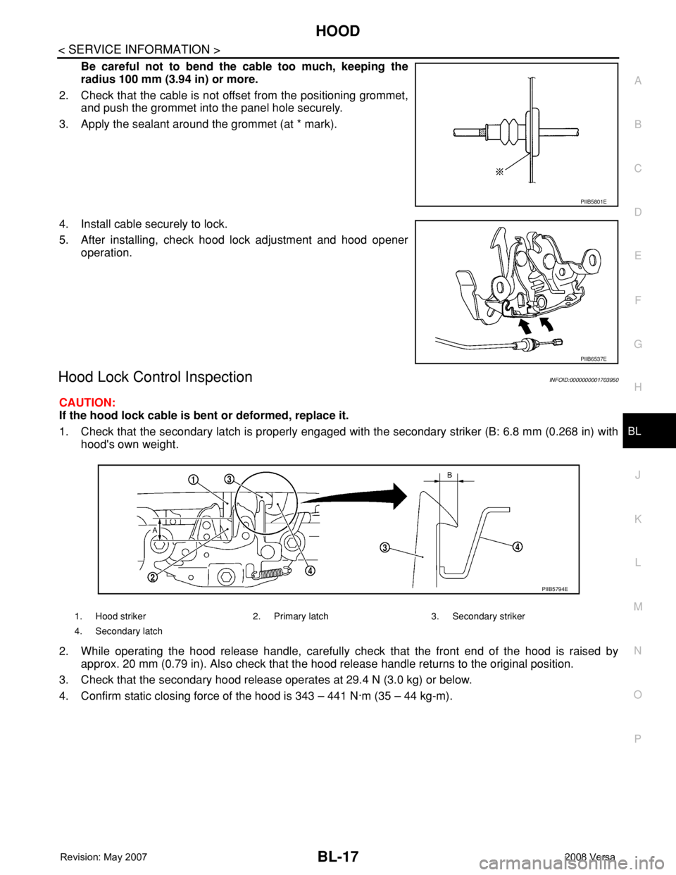
Be careful not to bend the cable too much, keeping the
radius 100 mm (3.94 in) or more.
2. Check that the cable is not offset from the positioning grommet,
and push the grommet into the panel hole securely.
3. Apply the sealant around the grommet (at * mark).
4. Install cable securely to lock.
5. After installing, check hood lock adjustment and hood opener
operation.
Hood Lock Control InspectionINFOID:0000000001703950
CAUTION:
If the hood lock cable is bent or deformed, replace it.
1. Check that the secondary latch is properly engaged with the secondary striker (B: 6.8 mm (0.268 in) with
hood's own weight.
2. While operating the hood release handle, carefully check that the front end of the hood is raised by
approx. 20 mm (0.79 in). Also check that the hood release handle returns to the original position.
3. Check that the secondary hood release operates at 29.4 N (3.0 kg) or below.
4. Confirm static closing force of the hood is 343 – 441 N·m (35 – 44 kg-m).
PIIB5801E
PIIB6537E
1. Hood striker 2. Primary latch 3. Secondary striker
4. Secondary latch
PIIB5794E
Page 470 of 2771

BL-36
< SERVICE INFORMATION >
POWER DOOR LOCK SYSTEM
3. According to the trouble diagnosis chart, repair or replace the cause of the malfunction. Refer to BL-103,
"Trouble Diagnosis Symptom Chart" .
4. Does power door lock system operate normally? OK: GO TO 5, NG: GO TO 3.
5. Inspection End.
CONSULT-III Function (BCM)INFOID:0000000001703962
CONSULT-III can display each diagnostic item using the diagnostic test modes shown following.
WORK SUPPORT
DATA MONITOR
*: With Remote Keyless Entry system
**: With Intelligent Key system
ACTIVE TEST
BCM
diagnostic test itemDiagnostic mode Description
Inspection by partWORK SUPPORTSupports inspections and adjustments. Commands are transmitted to the
BCM for setting the status suitable for required operation, input/output sig-
nals are received from the BCM and received date is displayed.
DATA MONITOR Displays BCM input/output data in real time.
ACTIVE TESTOperation of electrical loads can be checked by sending drive signal to
them.
SELF-DIAG RESULTS Displays BCM self-diagnosis results.
CAN DIAG SUPPORT MNTRThe result of transmit/receive diagnosis of CAN communication can be
read.
ECU PART NUMBER BCM part number can be read.
CONFIGURATION Performs BCM configuration read/write functions.
Work item Description
DOOR LOCK-UNLOCK SET Select unlock mode can be changed in this mode. Selects ON-OFF of select unlock mode.
ANTI-LOCK OUT SET Key reminder door mode can be changed in this mode. Selects ON-OFF of key reminder door mode.
Monitor item Content
IGN ON SW Indicates [ON/OFF] condition of ignition switch in ON position.
KEY ON SW Indicates [ON/OFF] condition of key switch.
CDL LOCK SW Indicates [ON/OFF] condition of lock signal from door lock and unlock switch.
CDL UNLOCK SW Indicates [ON/OFF] condition of unlock signal from door lock and unlock switch.
DOOR SW-DR Indicates [ON/OFF] condition of front door switch LH.
DOOR SW-AS Indicates [ON/OFF] condition of front door switch RH.
DOOR SW-RR Indicates [ON/OFF] condition of rear door switch RH.
DOOR SW-RL Indicates [ON/OFF] condition of rear door switch LH.
BACK DOOR SW Indicates [ON/OFF] condition of back door switch.
KEY CYL LK-SW Indicates [ON/OFF] condition of lock signal from key cylinder.
KEY CYL UN-SW Indicates [ON/OFF] condition of unlock signal from key cylinder.
KEYLESS LOCK* Indicates [ON/OFF] condition of lock signal from keyfob.
KEYLESS UNLOCK* Indicates [ON/OFF] condition of unlock signal from keyfob.
I-KEY LOCK** Indicates [ON/OFF] condition of lock signal from door request switch.
I-KEY UNLOCK** Indicates [ON/OFF] condition of unlock signal from door request switch.
Page 492 of 2771
BL-58
< SERVICE INFORMATION >
REMOTE KEYLESS ENTRY SYSTEM
3. Perform the Preliminary Check. Refer to LT- 11 , "Preliminary Check" .
4. Check symptom and repair or replace the component.
5. Does the remote keyless entry system operate normally? If YES, GO TO 6. If NO, GO TO 4.
6. INSPECTION END
Preliminary CheckINFOID:0000000001703980
CHECK BCM CONFIGURATION
1.CHECK BCM CONFIGURATION
Confirm BCM configuration for "KEYLESS ENTRY" is set to "WITH". Refer to BCS-17, "
Configuration" .
OK or NG
OK >> Refer to BL-59, "Work Flow" .
NG >> Change BCM configuration for "KEYLESS ENTRY" to "WITH". Refer to BCS-17, "
Configuration" .
CONSULT-III Function (BCM)INFOID:0000000001703981
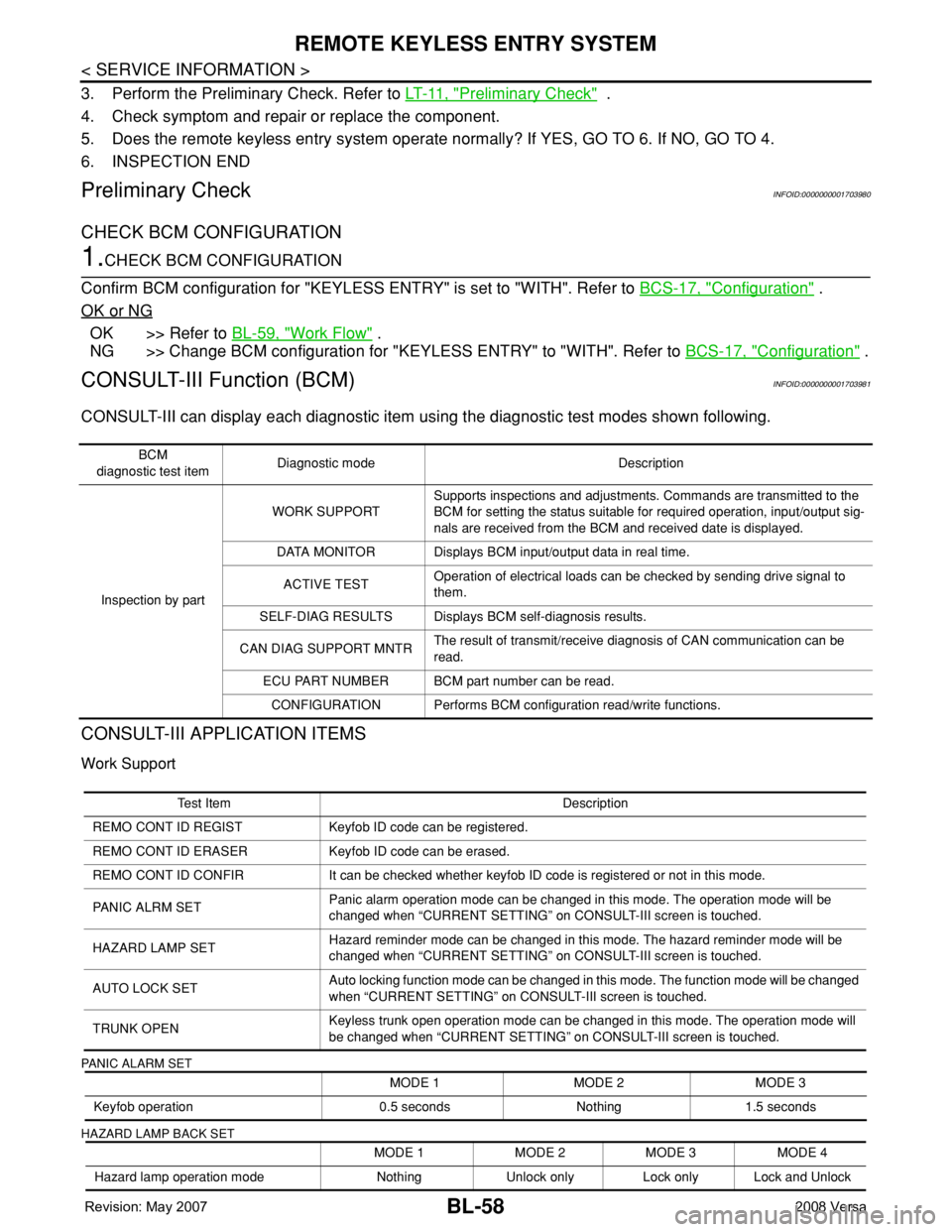
CONSULT-III can display each diagnostic item using the diagnostic test modes shown following.
CONSULT-III APPLICATION ITEMS
Work Support
PANIC ALARM SET
HAZARD LAMP BACK SET
BCM
diagnostic test itemDiagnostic mode Description
Inspection by partWORK SUPPORTSupports inspections and adjustments. Commands are transmitted to the
BCM for setting the status suitable for required operation, input/output sig-
nals are received from the BCM and received date is displayed.
DATA MONITOR Displays BCM input/output data in real time.
ACTIVE TESTOperation of electrical loads can be checked by sending drive signal to
them.
SELF-DIAG RESULTS Displays BCM self-diagnosis results.
CAN DIAG SUPPORT MNTRThe result of transmit/receive diagnosis of CAN communication can be
read.
ECU PART NUMBER BCM part number can be read.
CONFIGURATION Performs BCM configuration read/write functions.
Test Item Description
REMO CONT ID REGIST Keyfob ID code can be registered.
REMO CONT ID ERASER Keyfob ID code can be erased.
REMO CONT ID CONFIR It can be checked whether keyfob ID code is registered or not in this mode.
PANIC ALRM SETPanic alarm operation mode can be changed in this mode. The operation mode will be
changed when “CURRENT SETTING” on CONSULT-III screen is touched.
HAZARD LAMP SETHazard reminder mode can be changed in this mode. The hazard reminder mode will be
changed when “CURRENT SETTING” on CONSULT-III screen is touched.
AUTO LOCK SETAuto locking function mode can be changed in this mode. The function mode will be changed
when “CURRENT SETTING” on CONSULT-III screen is touched.
TRUNK OPENKeyless trunk open operation mode can be changed in this mode. The operation mode will
be changed when “CURRENT SETTING” on CONSULT-III screen is touched.
MODE 1 MODE 2 MODE 3
Keyfob operation 0.5 seconds Nothing 1.5 seconds
MODE 1 MODE 2 MODE 3 MODE 4
Hazard lamp operation mode Nothing Unlock only Lock only Lock and Unlock
Page 535 of 2771
INTELLIGENT KEY SYSTEM
BL-101
< SERVICE INFORMATION >
C
D
E
F
G
H
J
K
L
MA
B
BL
N
O
P
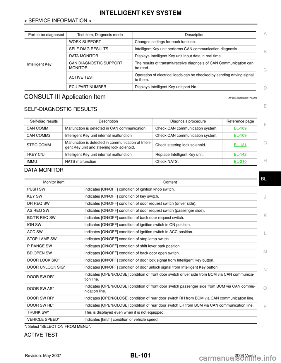
CONSULT-III Application ItemINFOID:0000000001704011
SELF-DIAGNOSTIC RESULTS
DATA MONITOR
*: Select “SELECTION FROM MENU”.
ACTIVE TEST
Part to be diagnosed Test item, Diagnosis mode Description
Intelligent KeyWORK SUPPORT Changes settings for each function.
SELF-DIAG RESULTS Intelligent Key unit performs CAN communication diagnosis.
DATA MONITOR Displays Intelligent Key unit input data in real time.
CAN DIAGNOSTIC SUPPORT
MONITORThe results of transmit/receive diagnosis of CAN Communication can
be read.
ACTIVE TESTOperation of electrical loads can be checked by sending driving signal
to them.
ECU PART NUMBER Displays Intelligent Key unit part No.
Self-diag results Description Diagnosis procedure Reference page
CAN COMM Malfunction is detected in CAN communication. Check CAN communication system.BL-109
CAN COMM2 Intelligent Key unit internal malfunction Check CAN communication system.BL-109
STRG COMMMalfunction is detected in communication of Intelli-
gent Key unit and steering lock solenoid.Check steering lock solenoid.BL-131
I-KEY C/U Intelligent Key unit internal malfunction Replace Intelligent Key unit.BL-142
IMMU NATS malfunction Check NATS.BL-210
Monitor item Content
PUSH SW Indicates [ON/OFF] condition of ignition knob switch.
KEY SW Indicates [ON/OFF] condition of key switch.
DR REQ SW Indicates [ON/OFF] condition of door request switch (driver side).
AS REQ SW Indicates [ON/OFF] condition of door request switch (passenger side).
BD/TR REQ SW Indicates [ON/OFF] condition of back door request switch.
IGN SW Indicates [ON/OFF] condition of ignition switch in ON position.
ACC SW Indicates [ON/OFF] condition of ignition switch in ACC position.
STOP LAMP SW Indicates [ON/OFF] condition of stop lamp switch.
P RANGE SW Indicates [ON/OFF] condition of shift lever park position.
BD OPEN SW Indicates [ON/OFF] condition of back door open switch.
DOOR LOCK SIG* Indicates [ON/OFF] condition of door lock signal from Intelligent Key button.
DOOR UNLOCK SIG* Indicates [ON/OFF] condition of door unlock signal from Intelligent Key button
DOOR SW DR*Indicates [OPEN/CLOSE] condition of front door switch driver side from BCM via CAN communica-
tion line.
DOOR SW AS*Indicates [OPEN/CLOSE] condition of front door switch passenger side from BCM via CAN commu-
nication line.
DOOR SW RR* Indicates [OPEN/CLOSE] condition of rear door switch RH from BCM via CAN communication line.
DOOR SW RL* Indicates [OPEN/CLOSE] condition of rear door switch LH from BCM via CAN communication line.
TRUNK SW* This is displayed even when it is not equipped.
VEHICLE SPEED* Indicates [km/h] condition of vehicle speed.
Page 593 of 2771
BACK DOOR LOCK
BL-159
< SERVICE INFORMATION >
C
D
E
F
G
H
J
K
L
MA
B
BL
N
O
P
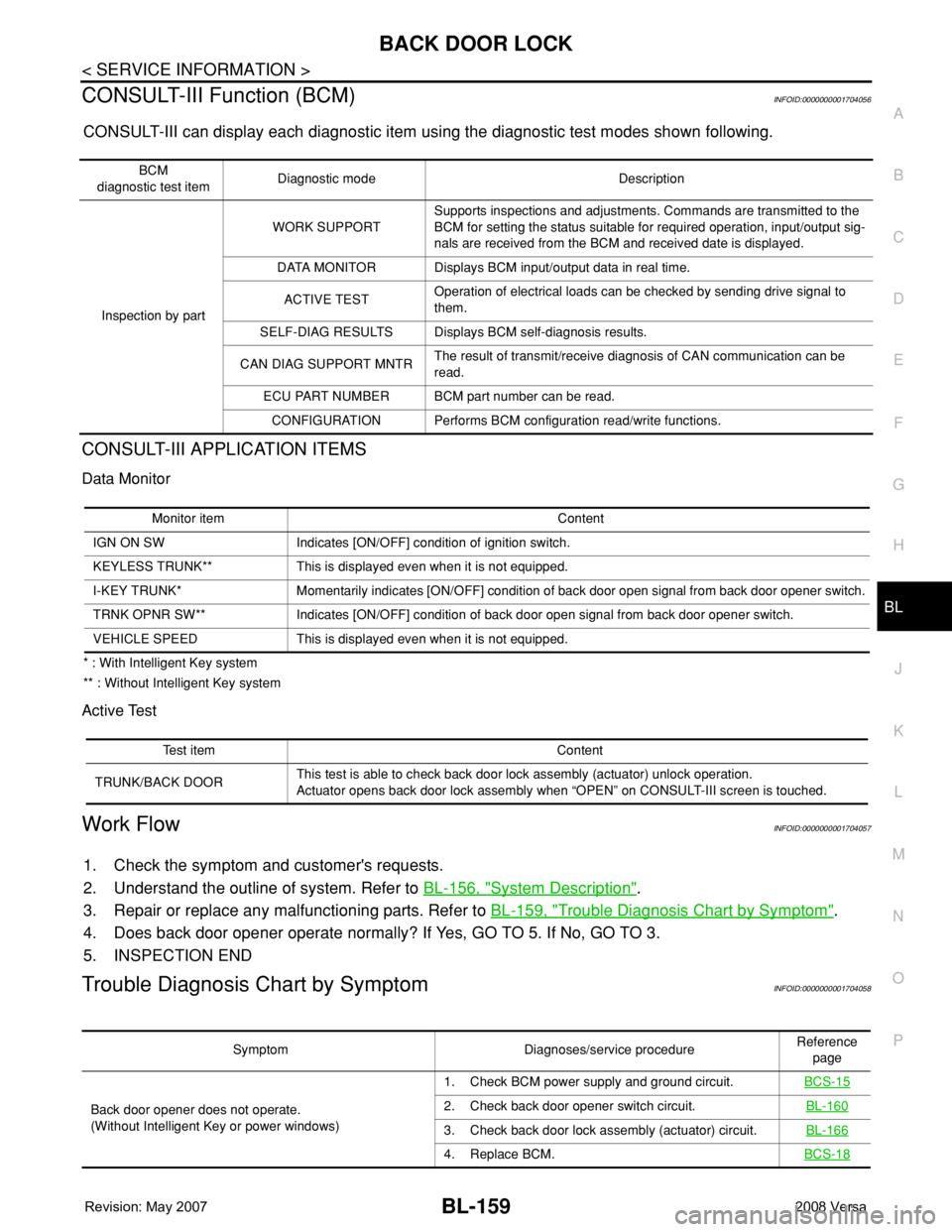
CONSULT-III Function (BCM)INFOID:0000000001704056
CONSULT-III can display each diagnostic item using the diagnostic test modes shown following.
CONSULT-III APPLICATION ITEMS
Data Monitor
* : With Intelligent Key system
** : Without Intelligent Key system
Active Test
Work FlowINFOID:0000000001704057
1. Check the symptom and customer's requests.
2. Understand the outline of system. Refer to BL-156, "
System Description".
3. Repair or replace any malfunctioning parts. Refer to BL-159, "
Trouble Diagnosis Chart by Symptom".
4. Does back door opener operate normally? If Yes, GO TO 5. If No, GO TO 3.
5. INSPECTION END
Trouble Diagnosis Chart by SymptomINFOID:0000000001704058
BCM
diagnostic test itemDiagnostic mode Description
Inspection by partWORK SUPPORTSupports inspections and adjustments. Commands are transmitted to the
BCM for setting the status suitable for required operation, input/output sig-
nals are received from the BCM and received date is displayed.
DATA MONITOR Displays BCM input/output data in real time.
ACTIVE TESTOperation of electrical loads can be checked by sending drive signal to
them.
SELF-DIAG RESULTS Displays BCM self-diagnosis results.
CAN DIAG SUPPORT MNTRThe result of transmit/receive diagnosis of CAN communication can be
read.
ECU PART NUMBER BCM part number can be read.
CONFIGURATION Performs BCM configuration read/write functions.
Monitor item Content
IGN ON SW Indicates [ON/OFF] condition of ignition switch.
KEYLESS TRUNK** This is displayed even when it is not equipped.
I-KEY TRUNK* Momentarily indicates [ON/OFF] condition of back door open signal from back door opener switch.
TRNK OPNR SW** Indicates [ON/OFF] condition of back door open signal from back door opener switch.
VEHICLE SPEED This is displayed even when it is not equipped.
Test item Content
TRUNK/BACK DOORThis test is able to check back door lock assembly (actuator) unlock operation.
Actuator opens back door lock assembly when “OPEN” on CONSULT-III screen is touched.
Symptom Diagnoses/service procedureReference
page
Back door opener does not operate.
(Without Intelligent Key or power windows)1. Check BCM power supply and ground circuit.BCS-15
2. Check back door opener switch circuit.BL-160
3. Check back door lock assembly (actuator) circuit.BL-166
4. Replace BCM.BCS-18
Page 610 of 2771
BL-176
< SERVICE INFORMATION >
TRUNK LID OPENER
CONSULT-III Function (BCM)
INFOID:0000000001704074
CONSULT-III can display each diagnostic item using the diagnostic test modes shown following.
CONSULT-III APPLICATION ITEMS
Data Monitor
* : With Intelligent Key system
** : Without Intelligent Key system
Active Test
Work FlowINFOID:0000000001704075
1. Check the symptom and customer's requests.
2. Understand the outline of system. Refer to BL-173, "
System Description".
3. Repair or replace any malfunctioning parts. Refer to BL-176, "
Trouble Diagnosis Chart by Symptom".
4. Does trunk lid opener operate normally? If Yes, GO TO 5. If No, GO TO 3.
5. INSPECTION END
Trouble Diagnosis Chart by SymptomINFOID:0000000001704076
BCM
diagnostic test itemDiagnostic mode Description
Inspection by partWORK SUPPORTSupports inspections and adjustments. Commands are transmitted to the
BCM for setting the status suitable for required operation, input/output sig-
nals are received from the BCM and received date is displayed.
DATA MONITOR Displays BCM input/output data in real time.
ACTIVE TESTOperation of electrical loads can be checked by sending drive signal to
them.
SELF-DIAG RESULTS Displays BCM self-diagnosis results.
CAN DIAG SUPPORT MNTRThe result of transmit/receive diagnosis of CAN communication can be
read.
ECU PART NUMBER BCM part number can be read.
CONFIGURATION Performs BCM configuration read/write functions.
Monitor item Content
IGN ON SW Indicates [ON/OFF] condition of ignition switch.
KEYLESS TRUNK** This is displayed even when it is not equipped.
I-KEY TRUNK* Momentarily indicates [ON/OFF] condition of trunk open signal from trunk lid opener switch.
TRNK OPNR SW Indicates [ON/OFF] condition of trunk open signal from trunk lid opener switch.
VEHICLE SPEED This is displayed even when it is not equipped.
Test item Content
TRUNK/BACK DOORThis test is able to check trunk lid lock assembly (actuator) unlock operation.
Actuator opens trunk lid lock assembly when “OPEN” on CONSULT-III screen is touched.
Symptom Diagnoses/service procedureReference
page
Trunk lid opener does not operate.
(Without Intelligent Key or power windows)1. Check BCM power supply and ground circuit.BCS-15
2. Check trunk lid opener switch circuit.BL-177
3. Check trunk lid lock assembly (actuator) circuit.BL-183
4. Replace BCM.BCS-18
Page 621 of 2771
VEHICLE SECURITY (THEFT WARNING) SYSTEM
BL-187
< SERVICE INFORMATION >
C
D
E
F
G
H
J
K
L
MA
B
BL
N
O
P
VEHICLE SECURITY (THEFT WARNING) SYSTEM
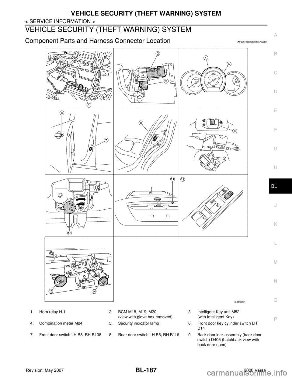
Component Parts and Harness Connector LocationINFOID:0000000001704083
LIIA2919E
1. Horn relay H-1 2. BCM M18, M19, M20
(view with glove box removed)3. Intelligent Key unit M52
(with Intelligent Key)
4. Combination meter M24 5. Security indicator lamp 6. Front door key cylinder switch LH
D14
7. Front door switch LH B8, RH B108 8. Rear door switch LH B6, RH B116 9. Back door lock assembly (back door
switch) D405 (hatchback view with
back door open)