Page 2434 of 2771

PG-1
ELECTRICAL
C
D
E
F
G
H
I
J
L
M
SECTION PG
A
B
PG
N
O
P
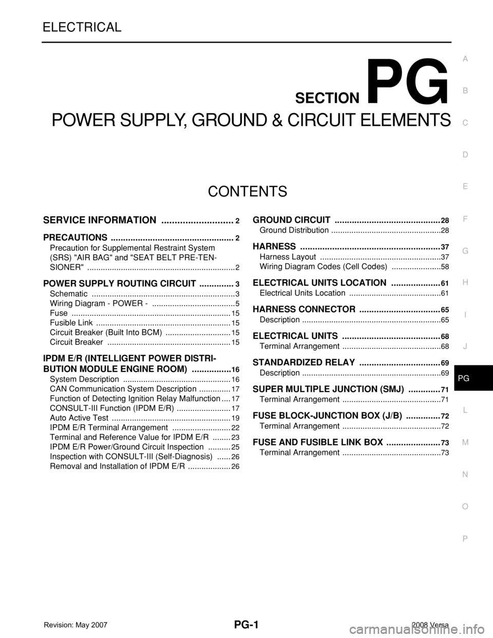
CONTENTS
POWER SUPPLY, GROUND & CIRCUIT ELEMENTS
SERVICE INFORMATION ............................2
PRECAUTIONS ...................................................2
Precaution for Supplemental Restraint System
(SRS) "AIR BAG" and "SEAT BELT PRE-TEN-
SIONER" ...................................................................
2
POWER SUPPLY ROUTING CIRCUIT ...............3
Schematic .................................................................3
Wiring Diagram - POWER - ......................................5
Fuse ........................................................................15
Fusible Link .............................................................15
Circuit Breaker (Built Into BCM) ..............................15
Circuit Breaker ........................................................15
IPDM E/R (INTELLIGENT POWER DISTRI-
BUTION MODULE ENGINE ROOM) .................
16
System Description .................................................16
CAN Communication System Description ...............17
Function of Detecting Ignition Relay Malfunction ....17
CONSULT-III Function (IPDM E/R) .........................17
Auto Active Test ......................................................19
IPDM E/R Terminal Arrangement ...........................22
Terminal and Reference Value for IPDM E/R .........23
IPDM E/R Power/Ground Circuit Inspection ...........25
Inspection with CONSULT-III (Self-Diagnosis) .......26
Removal and Installation of IPDM E/R ....................26
GROUND CIRCUIT ...........................................28
Ground Distribution ..................................................28
HARNESS .........................................................37
Harness Layout .......................................................37
Wiring Diagram Codes (Cell Codes) .......................58
ELECTRICAL UNITS LOCATION ....................61
Electrical Units Location ..........................................61
HARNESS CONNECTOR .................................65
Description ...............................................................65
ELECTRICAL UNITS ........................................68
Terminal Arrangement .............................................68
STANDARDIZED RELAY .................................69
Description ...............................................................69
SUPER MULTIPLE JUNCTION (SMJ) .............71
Terminal Arrangement .............................................71
FUSE BLOCK-JUNCTION BOX (J/B) ..............72
Terminal Arrangement .............................................72
FUSE AND FUSIBLE LINK BOX ......................73
Terminal Arrangement .............................................73
Page 2438 of 2771
POWER SUPPLY ROUTING CIRCUIT
PG-5
< SERVICE INFORMATION >
C
D
E
F
G
H
I
J
L
MA
B
PG
N
O
P
Wiring Diagram - POWER -INFOID:0000000001704692
BATTERY POWER SUPPLY — IGNITION SWITCH IN ANY POSITION
AWMWA0065G
Page 2491 of 2771

PG-58
< SERVICE INFORMATION >
HARNESS
Wiring Diagram Codes (Cell Codes)
INFOID:0000000001704709
Use the chart below to find out what each wiring diagram code stands for.
Refer to the wiring diagram code in the alphabetical index to find the location (page number) of each wiring
diagram.
D3 D404 W/3 : Rear wiper motor
D4 D405 W/4 : Back door lock assembly
D4 D406 W/2 : Back door request switch
E2 D407 W/2 : High mounted stop lamp
D4 D408 BR/2 : Back door opener switch
E4 D409 B/1 : Condenser-1
C2 D410 — : Body ground
E3 D411 B/1 : Condenser-1
E1 D412 B/1 : Rear window defogger (+)
C2 D413 B/1 : Rear window defogger (-)
F3 D414 — : Body ground
Code Section Wiring Diagram Name
ABS BRC Anti-lock Brake System
A/C,M MTC Manual Air Conditioner
APPS1 EC Accelerator Pedal Position Sensor
A/F EC Air Fuel Ratio Sensor 1
A/FH EC Air Fuel Ratio Sensor 1 Heater
APPS2 EC Accelerator Pedal Position Sensor
APPS3 EC Accelerator Pedal Position Sensor
ASC/BS EC ASCD Brake Switch
ASC/SW EC ASCD Steering Switch
ASCBOF EC ASCD Brake Switch
ASCIND EC ASCD Indicator
AT/IND DI A/T Indicator Lamp
AUDIO AV Audio
BACK/L LT Back-up Lamp
BA/FTS AT A/T Fluid Temperature Sensor and TCM Power Supply
B/DOOR BL Back Door Opener
BRK/SW EC Brake Switch
CAN AT CAN Communication Line
CAN CVT CAN Communication Line
CAN EC CAN Communication Line
CAN LAN CAN System
CHARGE SC Charging System
CHIME DI Warning Chime
COOL/F EC Cooling Fan Control
COMBSW LT Combination Switch
CVTIND DI CVT Indicator Lamp
D/LOCK BL Power Door Lock
DEF GW Rear Window Defogger
DTRL LT Headlamp - With Daytime Light System
ECTS EC Engine Coolant Temperature Sensor
ENGSS AT Engine Speed Signal
EPS STC Electronic Controlled Power Steering
ETC1 EC Electric Throttle Control Function
Page 2531 of 2771

RF-1
BODY
C
D
E
F
G
H
J
K
L
M
SECTION RF
A
B
RF
N
O
P
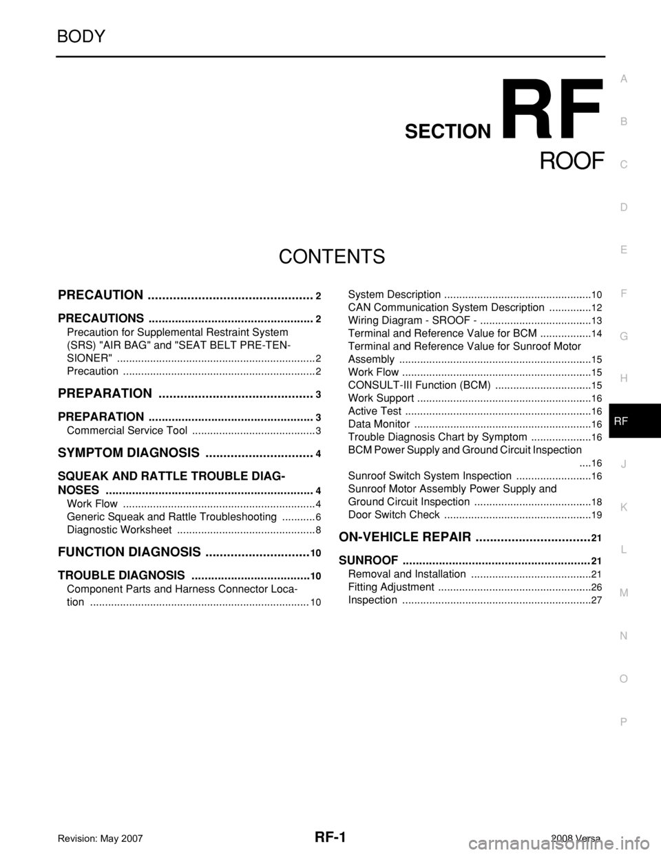
CONTENTS
ROOF
PRECAUTION ...............................................2
PRECAUTIONS ...................................................2
Precaution for Supplemental Restraint System
(SRS) "AIR BAG" and "SEAT BELT PRE-TEN-
SIONER" ...................................................................
2
Precaution .................................................................2
PREPARATION ............................................3
PREPARATION ...................................................3
Commercial Service Tool ..........................................3
SYMPTOM DIAGNOSIS ...............................4
SQUEAK AND RATTLE TROUBLE DIAG-
NOSES ................................................................
4
Work Flow .................................................................4
Generic Squeak and Rattle Troubleshooting ............6
Diagnostic Worksheet ...............................................8
FUNCTION DIAGNOSIS ..............................10
TROUBLE DIAGNOSIS .....................................10
Component Parts and Harness Connector Loca-
tion ..........................................................................
10
System Description ..................................................10
CAN Communication System Description ...............12
Wiring Diagram - SROOF - ......................................13
Terminal and Reference Value for BCM ..................14
Terminal and Reference Value for Sunroof Motor
Assembly .................................................................
15
Work Flow ................................................................15
CONSULT-III Function (BCM) .................................15
Work Support ...........................................................16
Active Test ...............................................................16
Data Monitor ............................................................16
Trouble Diagnosis Chart by Symptom .....................16
BCM Power Supply and Ground Circuit Inspection
....
16
Sunroof Switch System Inspection ..........................16
Sunroof Motor Assembly Power Supply and
Ground Circuit Inspection ........................................
18
Door Switch Check ..................................................19
ON-VEHICLE REPAIR .................................21
SUNROOF .........................................................21
Removal and Installation .........................................21
Fitting Adjustment ....................................................26
Inspection ................................................................27
Page 2543 of 2771
TROUBLE DIAGNOSIS
RF-13
< FUNCTION DIAGNOSIS >
C
D
E
F
G
H
J
K
L
MA
B
RF
N
O
P
Wiring Diagram - SROOF -INFOID:0000000001704194
WIWA1950E
Page 2583 of 2771

SC-1
ELECTRICAL
C
D
E
F
G
H
I
J
L
M
SECTION SC
A
B
SC
N
O
P
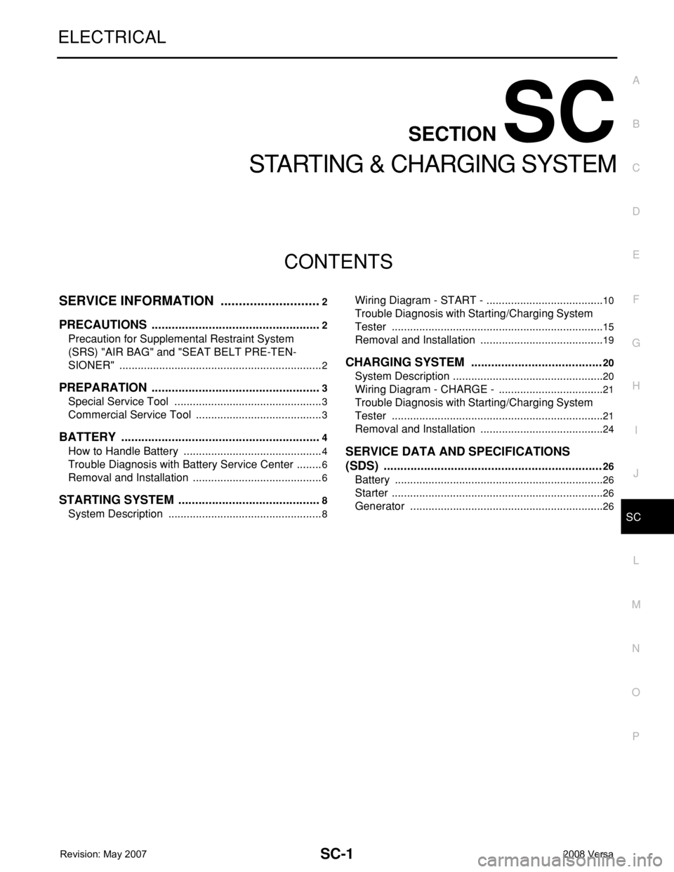
CONTENTS
STARTING & CHARGING SYSTEM
SERVICE INFORMATION ............................2
PRECAUTIONS ...................................................2
Precaution for Supplemental Restraint System
(SRS) "AIR BAG" and "SEAT BELT PRE-TEN-
SIONER" ...................................................................
2
PREPARATION ...................................................3
Special Service Tool .................................................3
Commercial Service Tool ..........................................3
BATTERY ............................................................4
How to Handle Battery ..............................................4
Trouble Diagnosis with Battery Service Center .........6
Removal and Installation ...........................................6
STARTING SYSTEM ...........................................8
System Description ...................................................8
Wiring Diagram - START - .......................................10
Trouble Diagnosis with Starting/Charging System
Tester ......................................................................
15
Removal and Installation .........................................19
CHARGING SYSTEM .......................................20
System Description ..................................................20
Wiring Diagram - CHARGE - ...................................21
Trouble Diagnosis with Starting/Charging System
Tester ......................................................................
21
Removal and Installation .........................................24
SERVICE DATA AND SPECIFICATIONS
(SDS) .................................................................
26
Battery .....................................................................26
Starter ......................................................................26
Generator ................................................................26
Page 2592 of 2771
SC-10
< SERVICE INFORMATION >
STARTING SYSTEM
Wiring Diagram - START -
INFOID:0000000001704349
M/T Models
WKWA4964E
Page 2603 of 2771
CHARGING SYSTEM
SC-21
< SERVICE INFORMATION >
C
D
E
F
G
H
I
J
L
MA
B
SC
N
O
P
Wiring Diagram - CHARGE -INFOID:0000000001704353
Trouble Diagnosis with Starting/Charging System TesterINFOID:0000000001704354
For charging system testing, use Starting/Charging System Tester (J-44373). For details, refer to Technical
Service Bulletin.
WKWA4970E