2008 NISSAN LATIO suspension
[x] Cancel search: suspensionPage 1844 of 2771
FSU-10
< SERVICE INFORMATION >
FRONT SUSPENSION ASSEMBLY
Removal and Installation
INFOID:0000000001703724
REMOVAL
1. Separate intermediate shaft from steering gear pinion shaft. Refer to PS-9, "Removal and Installation".
2. Remove front tires from vehicle using a power tool.
3. Remove wheel sensor from steering knuckle. Refer to BRC-32
.
CAUTION:
Do not pull on wheel sensor harness.
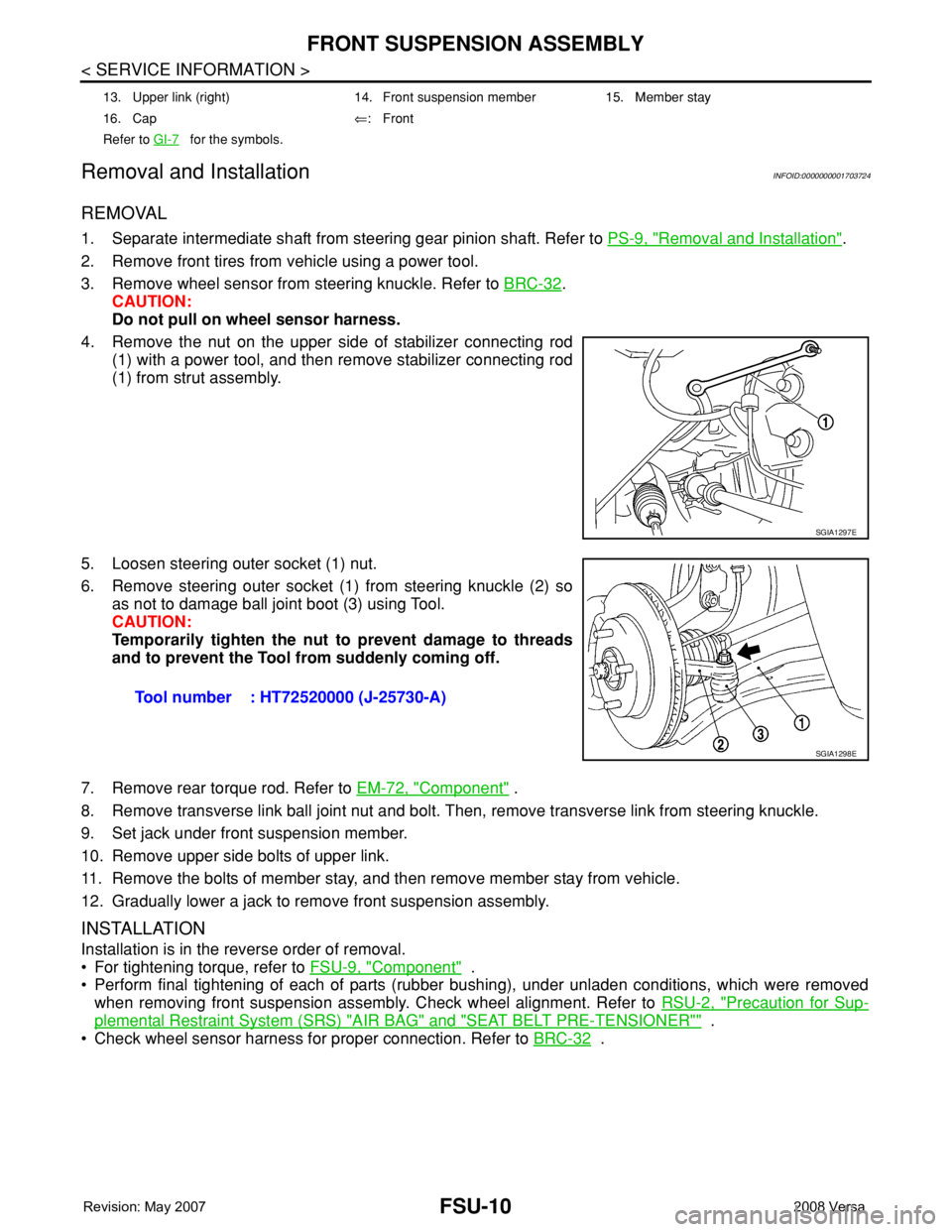
4. Remove the nut on the upper side of stabilizer connecting rod
(1) with a power tool, and then remove stabilizer connecting rod
(1) from strut assembly.
5. Loosen steering outer socket (1) nut.
6. Remove steering outer socket (1) from steering knuckle (2) so
as not to damage ball joint boot (3) using Tool.
CAUTION:
Temporarily tighten the nut to prevent damage to threads
and to prevent the Tool from suddenly coming off.
7. Remove rear torque rod. Refer to EM-72, "
Component" .
8. Remove transverse link ball joint nut and bolt. Then, remove transverse link from steering knuckle.
9. Set jack under front suspension member.
10. Remove upper side bolts of upper link.
11. Remove the bolts of member stay, and then remove member stay from vehicle.
12. Gradually lower a jack to remove front suspension assembly.
INSTALLATION
Installation is in the reverse order of removal.
• For tightening torque, refer to FSU-9, "
Component" .
• Perform final tightening of each of parts (rubber bushing), under unladen conditions, which were removed
when removing front suspension assembly. Check wheel alignment. Refer to RSU-2, "
Precaution for Sup-
plemental Restraint System (SRS) "AIR BAG" and "SEAT BELT PRE-TENSIONER"" .
• Check wheel sensor harness for proper connection. Refer to BRC-32
.
13. Upper link (right) 14. Front suspension member 15. Member stay
16. Cap⇐:Front
Refer to GI-7
for the symbols.
SGIA1297E
Tool number : HT72520000 (J-25730-A)
SGIA1298E
Page 1848 of 2771
FSU-14
< SERVICE INFORMATION >
TRANSVERSE LINK
TRANSVERSE LINK
Removal and InstallationINFOID:0000000001703727
REMOVAL
1. Remove front tires using power tool.
2. Remove transverse link ball joint nut and bolt. Then, remove transverse link from steering knuckle.
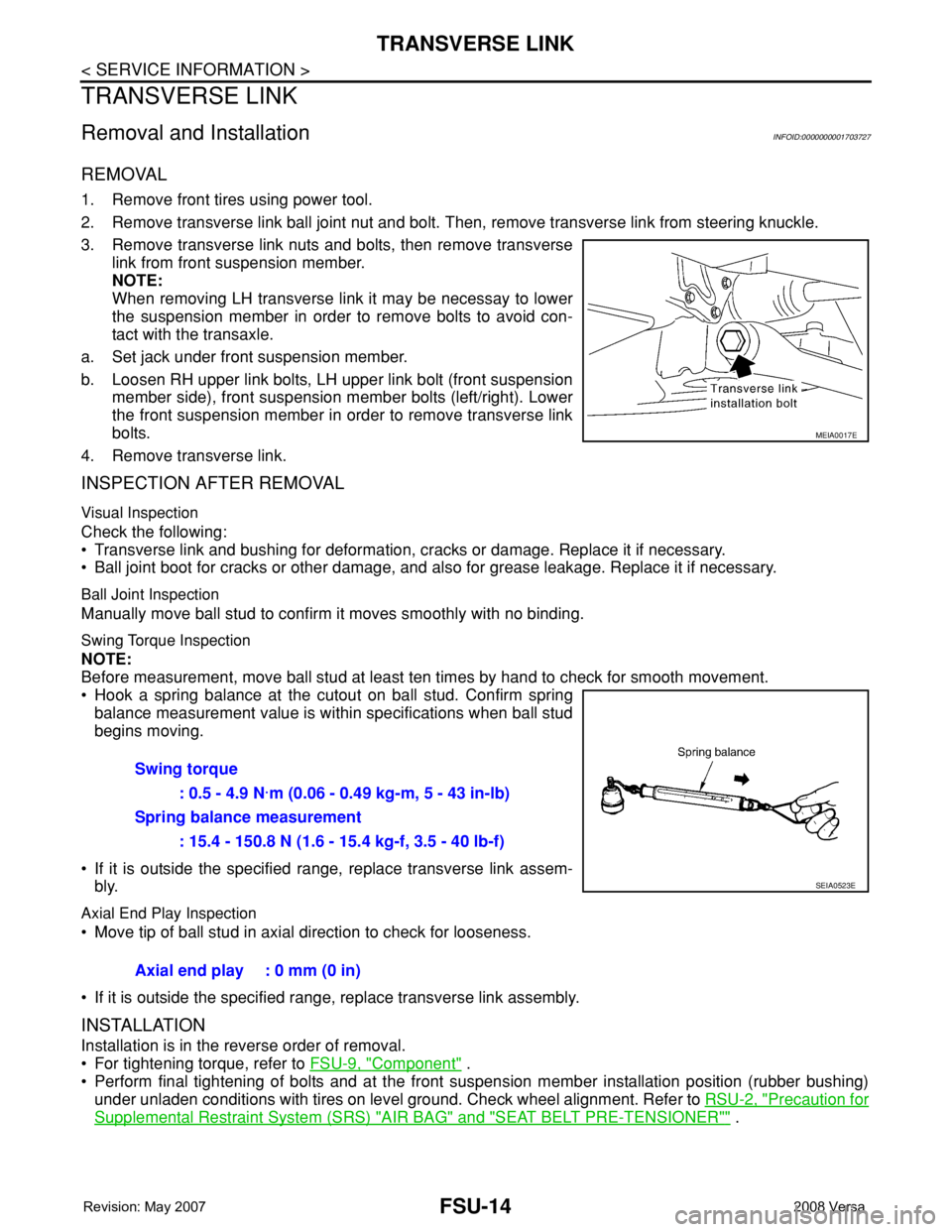
3. Remove transverse link nuts and bolts, then remove transverse
link from front suspension member.
NOTE:
When removing LH transverse link it may be necessay to lower
the suspension member in order to remove bolts to avoid con-
tact with the transaxle.
a. Set jack under front suspension member.
b. Loosen RH upper link bolts, LH upper link bolt (front suspension
member side), front suspension member bolts (left/right). Lower
the front suspension member in order to remove transverse link
bolts.
4. Remove transverse link.
INSPECTION AFTER REMOVAL
Visual Inspection
Check the following:
• Transverse link and bushing for deformation, cracks or damage. Replace it if necessary.
• Ball joint boot for cracks or other damage, and also for grease leakage. Replace it if necessary.
Ball Joint Inspection
Manually move ball stud to confirm it moves smoothly with no binding.
Swing Torque Inspection
NOTE:
Before measurement, move ball stud at least ten times by hand to check for smooth movement.
• Hook a spring balance at the cutout on ball stud. Confirm spring
balance measurement value is within specifications when ball stud
begins moving.
• If it is outside the specified range, replace transverse link assem-
bly.
Axial End Play Inspection
• Move tip of ball stud in axial direction to check for looseness.
• If it is outside the specified range, replace transverse link assembly.
INSTALLATION
Installation is in the reverse order of removal.
• For tightening torque, refer to FSU-9, "
Component" .
• Perform final tightening of bolts and at the front suspension member installation position (rubber bushing)
under unladen conditions with tires on level ground. Check wheel alignment. Refer to RSU-2, "
Precaution for
Supplemental Restraint System (SRS) "AIR BAG" and "SEAT BELT PRE-TENSIONER"" .
MEIA0017E
Swing torque
: 0.5 - 4.9 N·m (0.06 - 0.49 kg-m, 5 - 43 in-lb)
Spring balance measurement
: 15.4 - 150.8 N (1.6 - 15.4 kg-f, 3.5 - 40 lb-f)
SEIA0523E
Axial end play : 0 mm (0 in)
Page 1849 of 2771
STABILIZER BAR
FSU-15
< SERVICE INFORMATION >
C
D
F
G
H
I
J
K
L
MA
B
FSU
N
O
P
STABILIZER BAR
Removal and InstallationINFOID:0000000001703728
REMOVAL
1. Separate intermediate shaft from steering gear pinion shaft. Refer to PS-9, "Removal and Installation" .
2. Remove front tires using power tool.
3. Remove the nut on the lower side of stabilizer connecting rod using power tool, and then remove stabilizer
connecting rod from stabilizer bar.
4. If necessary remove stabilize connecting rod upper nut using power tool. Separate stabilizer connecting
rod and strut.
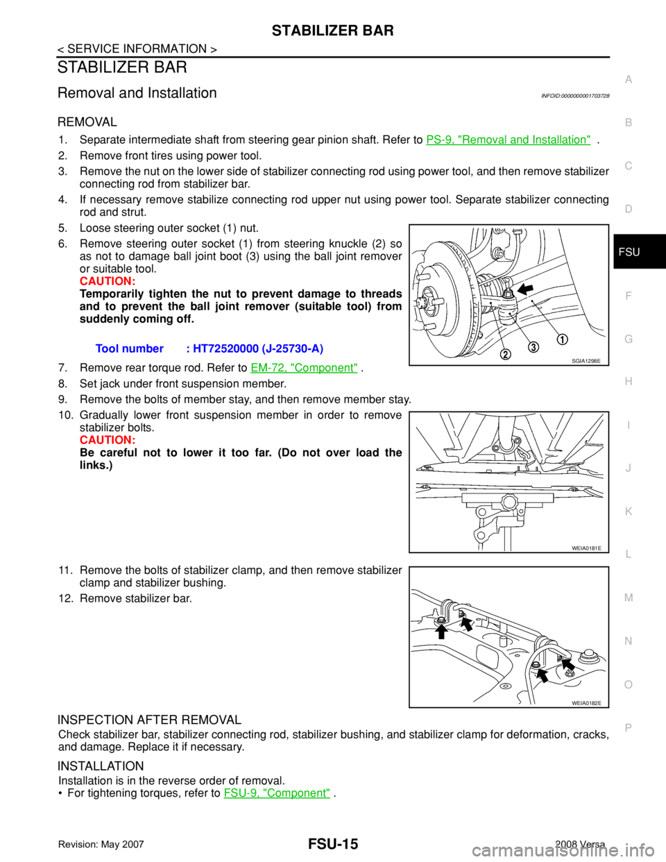
5. Loose steering outer socket (1) nut.
6. Remove steering outer socket (1) from steering knuckle (2) so
as not to damage ball joint boot (3) using the ball joint remover
or suitable tool.
CAUTION:
Temporarily tighten the nut to prevent damage to threads
and to prevent the ball joint remover (suitable tool) from
suddenly coming off.
7. Remove rear torque rod. Refer to EM-72, "
Component" .
8. Set jack under front suspension member.
9. Remove the bolts of member stay, and then remove member stay.
10. Gradually lower front suspension member in order to remove
stabilizer bolts.
CAUTION:
Be careful not to lower it too far. (Do not over load the
links.)
11. Remove the bolts of stabilizer clamp, and then remove stabilizer
clamp and stabilizer bushing.
12. Remove stabilizer bar.
INSPECTION AFTER REMOVAL
Check stabilizer bar, stabilizer connecting rod, stabilizer bushing, and stabilizer clamp for deformation, cracks,
and damage. Replace it if necessary.
INSTALLATION
Installation is in the reverse order of removal.
• For tightening torques, refer to FSU-9, "
Component" . Tool number : HT72520000 (J-25730-A)
SGIA1298E
WEIA0181E
WEIA0182E
Page 1889 of 2771
GI-38
< SERVICE INFORMATION >
LIFTING POINT
LIFTING POINT
Special Service ToolINFOID:0000000001702449
CAUTION:
• Every time the vehicle is lifted up, maintain the complete vehicle curb condition.
• Since the vehicle's center of gravity changes when removing main parts on the front side (engine,
transmission, suspension etc.), support a jack up point on the rear side garage jack with a mission
jack or equivalent.
• Since the vehicle's center of gravity changes when removing main parts on the rear side (rear axle,
suspension, etc.), support a jack up point on the front side garage jack with a mission jack or equiv-
alent.
• Be careful not to smash or do not do anything that would affect piping parts.
Garage Jack and Safety Stand and 2-Pole LiftINFOID:0000000001702450
WARNING:
• Park the vehicle on a level surface when using the jack. Make sure to avoid damaging pipes, tubes,
etc. under the vehicle.
• Never get under the vehicle while it is supported only by the jack. Always use safety stands when
you have to get under the vehicle.
• Place wheel chocks at both front and back of the wheels on the ground.
• When lifting the vehicle, open the lift arms as wide as possible and ensure that the front and rear of
the vehicle are well balanced.
• When setting the lift arm, do not allow the arm to contact the brake tubes, brake cable, fuel lines and
sill spoiler.
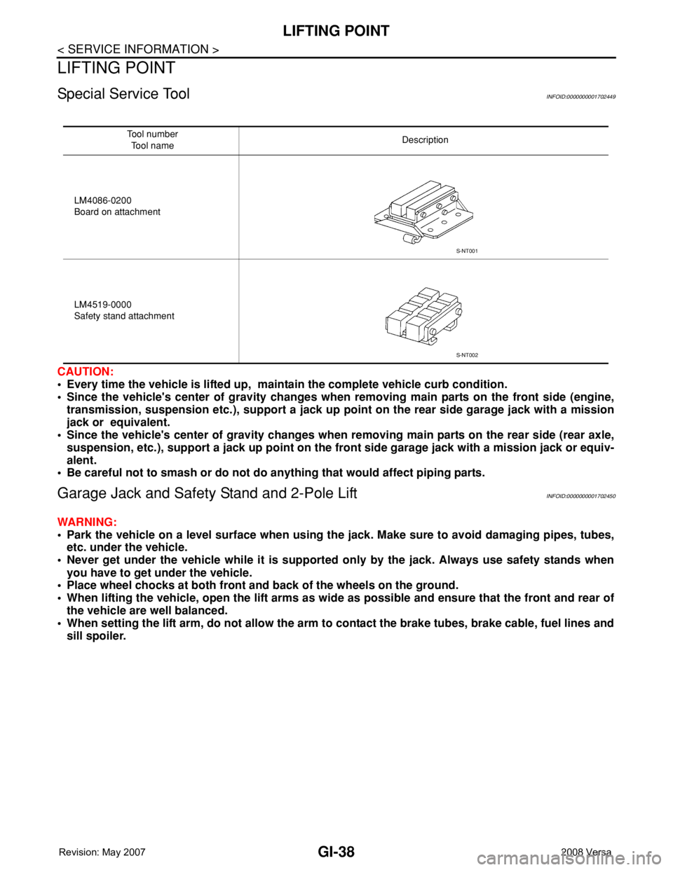
Tool number
Tool nameDescription
LM4086-0200
Board on attachment
LM4519-0000
Safety stand attachment
S-NT001
S-NT002
Page 1891 of 2771
GI-40
< SERVICE INFORMATION >
TOW TRUCK TOWING
TOW TRUCK TOWING
Tow Truck TowingINFOID:0000000001702452
CAUTION:
• All applicable local laws regarding the towing operation must be obeyed.
• It is necessary to use proper towing equipment to avoid possible damage to the vehicle during tow-
ing operation. Towing is in accordance with Towing Procedure Manual at dealer.
• Always attach safety chains before towing.
• When towing, make sure that the transmission, steering system and power train are in good order. If
any unit is damaged, dollies must be used.
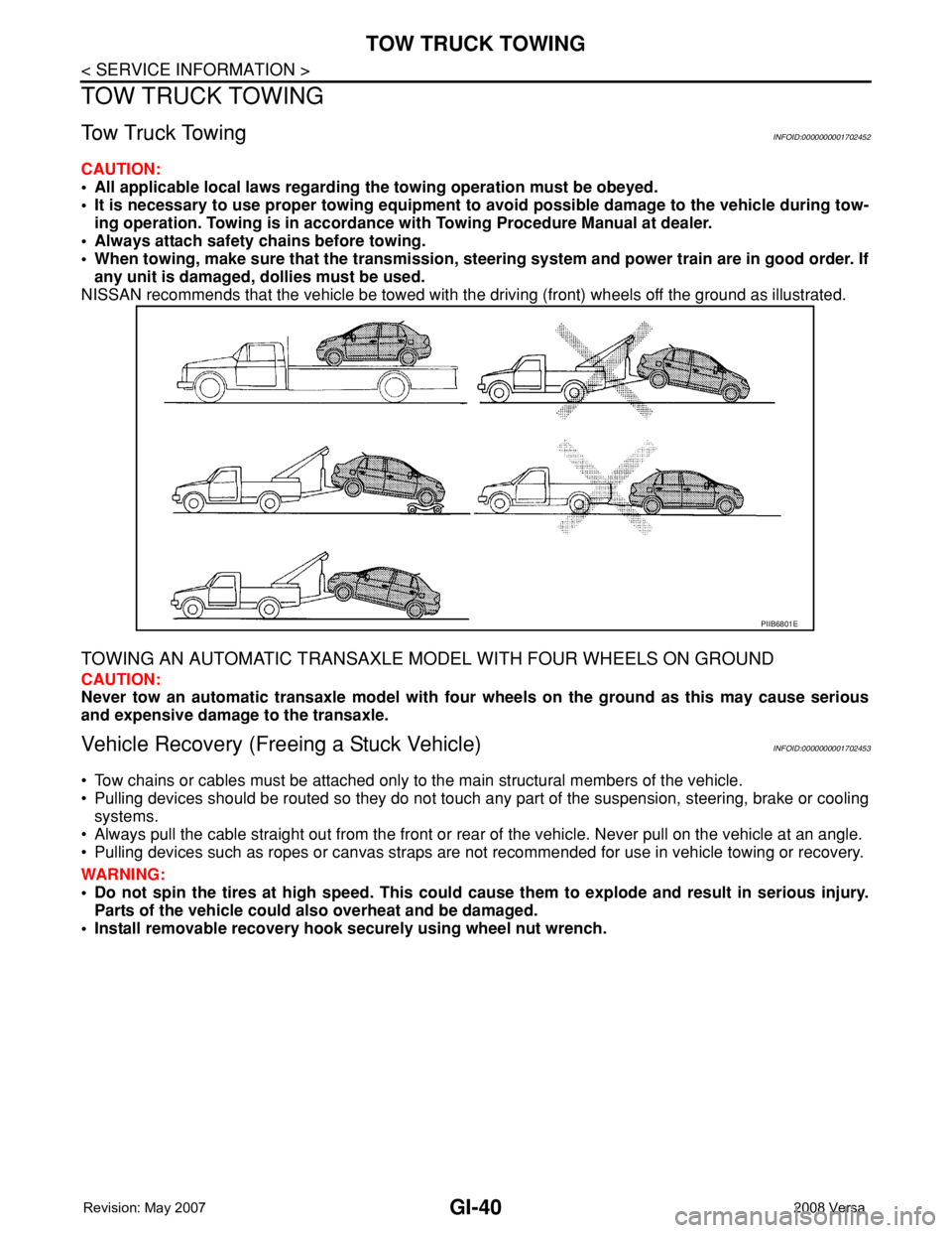
NISSAN recommends that the vehicle be towed with the driving (front) wheels off the ground as illustrated.
TOWING AN AUTOMATIC TRANSAXLE MODEL WITH FOUR WHEELS ON GROUND
CAUTION:
Never tow an automatic transaxle model with four wheels on the ground as this may cause serious
and expensive damage to the transaxle.
Vehicle Recovery (Freeing a Stuck Vehicle)INFOID:0000000001702453
• Tow chains or cables must be attached only to the main structural members of the vehicle.
• Pulling devices should be routed so they do not touch any part of the suspension, steering, brake or cooling
systems.
• Always pull the cable straight out from the front or rear of the vehicle. Never pull on the vehicle at an angle.
• Pulling devices such as ropes or canvas straps are not recommended for use in vehicle towing or recovery.
WARNING:
• Do not spin the tires at high speed. This could cause them to explode and result in serious injury.
Parts of the vehicle could also overheat and be damaged.
• Install removable recovery hook securely using wheel nut wrench.
PIIB6801E
Page 2261 of 2771
MA-1
MAINTENANCE
C
D
E
F
G
H
I
J
K
M
SECTION MA
A
B
MA
N
O
P
CONTENTS
MAINTENANCE
SERVICE INFORMATION ............................2
PRECAUTIONS ...................................................2
Precaution for Supplemental Restraint System
(SRS) "AIR BAG" and "SEAT BELT PRE-TEN-
SIONER" ...................................................................
2
PREPARATION ...................................................3
Special Service Tool .................................................3
Commercial Service Tool ..........................................3
GENERAL MAINTENANCE ................................4
Explanation of General Maintenance ........................4
General Maintenance ................................................4
PERIODIC MAINTENANCE ................................6
Introduction of Periodic Maintenance ........................6
Schedule 1 ................................................................6
Schedule 2 ................................................................8
RECOMMENDED FLUIDS AND LUBRI-
CANTS ................................................................
10
Fluids and Lubricants ..............................................10
SAE Viscosity Number ............................................10
Anti-freeze Coolant Mixture Ratio ...........................11
ENGINE MAINTENANCE ...................................12
Drive Belts ...............................................................12
Checking Drive Belts ...............................................12
Tension Adjustment ................................................12
Changing Engine Coolant .......................................12
Inspection ................................................................14
Checking Fuel Line ..................................................14
Changing Air Cleaner Filter .....................................14
Changing Engine Oil ................................................15
Engine Oil Filter .......................................................16
Changing Spark Plugs .............................................17
Checking EVAP Vapor Line .....................................18
CHASSIS AND BODY MAINTENANCE ...........19
Changing In-cabin Microfilter ...................................19
Checking Exhaust System .......................................19
Checking CVT Fluid .................................................19
Changing CVT Fluid ................................................20
Checking Clutch Fluid Level and Leaks ..................21
Checking Clutch System .........................................21
Checking M/T Oil .....................................................21
Changing M/T Oil .....................................................21
Checking A/T Fluid ..................................................22
Changing A/T Fluid ..................................................22
Balancing Wheels ....................................................23
Rotation ...................................................................23
Checking Brake Fluid Level and Leaks ...................23
Checking Brake Line and Cables ............................24
Changing Brake Fluid ..............................................24
Checking Disc Brake ...............................................24
Axle and Suspension Parts .....................................25
Drive Shaft ...............................................................26
Lubricating Locks, Hinges and Hood Latch .............27
Checking Seat Belts, Buckles, Retractors, An-
chors and Adjusters .................................................
27
Page 2268 of 2771
MA-8
< SERVICE INFORMATION >
PERIODIC MAINTENANCE
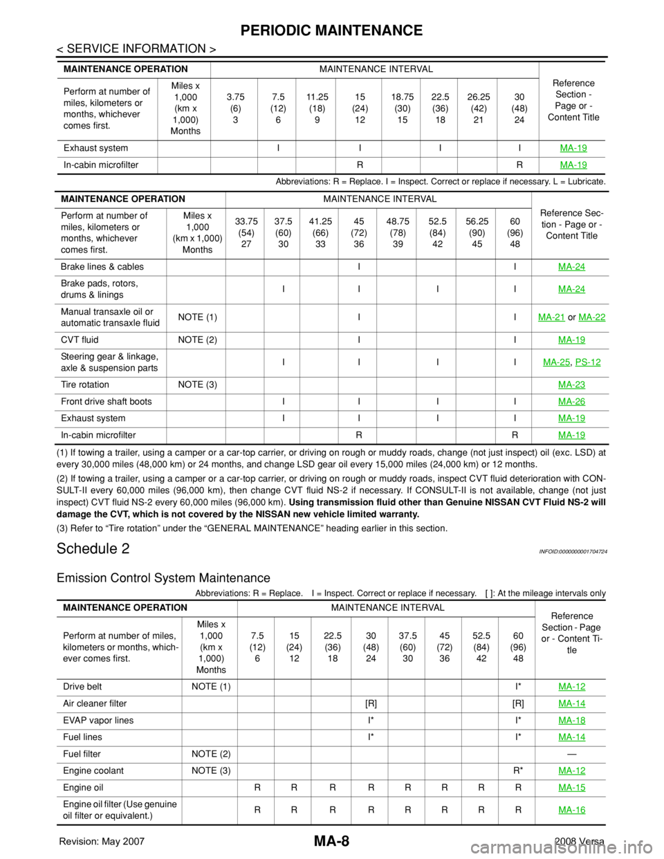
Abbreviations: R = Replace. I = Inspect. Correct or replace if necessary. L = Lubricate.
(1) If towing a trailer, using a camper or a car-top carrier, or driving on rough or muddy roads, change (not just inspect) oil (exc. LSD) at
every 30,000 miles (48,000 km) or 24 months, and change LSD gear oil every 15,000 miles (24,000 km) or 12 months.
(2) If towing a trailer, using a camper or a car-top carrier, or driving on rough or muddy roads, inspect CVT fluid deterioration with CON-
SULT-II every 60,000 miles (96,000 km), then change CVT fluid NS-2 if necessary. If CONSULT-II is not available, change (not just
inspect) CVT fluid NS-2 every 60,000 miles (96,000 km). Using transmission fluid other than Genuine NISSAN CVT Fluid NS-2 will
damage the CVT, which is not covered by the NISSAN new vehicle limited warranty.
(3) Refer to “Tire rotation” under the “GENERAL MAINTENANCE” heading earlier in this section.
Schedule 2INFOID:0000000001704724
Emission Control System Maintenance
Abbreviations: R = Replace. I = Inspect. Correct or replace if necessary. [ ]: At the mileage intervals only
Exhaust system I I I IMA-19
In-cabin microfilter R RMA-19
MAINTENANCE OPERATIONMAINTENANCE INTERVAL
Reference
Section -
Page or -
Content Title Perform at number of
miles, kilometers or
months, whichever
comes first.Miles x
1,000
(km x
1,000)
Months3.75
(6)
37.5
(12)
611 . 2 5
(18)
915
(24)
1218.75
(30)
1522.5
(36)
1826.25
(42)
2130
(48)
24
MAINTENANCE OPERATIONMAINTENANCE INTERVAL
Reference Sec-
tion - Page or -
Content Title Perform at number of
miles, kilometers or
months, whichever
comes first.Miles x
1,000
(km x 1,000)
Months33.75
(54)
2737.5
(60)
3041.25
(66)
3345
(72)
3648.75
(78)
3952.5
(84)
4256.25
(90)
4560
(96)
48
Brake lines & cables I IMA-24
Brake pads, rotors,
drums & liningsII I IMA-24
Manual transaxle oil or
automatic transaxle fluidNOTE (1) I IMA-21 or MA-22
CVT fluid NOTE (2) I IMA-19
Steering gear & linkage,
axle & suspension partsII I IMA-25, PS-12
Tire rotation NOTE (3)MA-23
Front drive shaft boots I I I IMA-26
Exhaust system I I I IMA-19
In-cabin microfilter R RMA-19
MAINTENANCE OPERATIONMAINTENANCE INTERVAL
Reference
Section - Page
or - Content Ti-
tle Perform at number of miles,
kilometers or months, which-
ever comes first.Miles x
1,000
(km x
1,000)
Months7.5
(12)
615
(24)
1222.5
(36)
1830
(48)
2437.5
(60)
3045
(72)
3652.5
(84)
4260
(96)
48
Drive belt NOTE (1) I*MA-12
Air cleaner filter [R] [R]MA-14
EVAP vapor lines I* I*MA-18
Fuel lines I* I*MA-14
Fuel filter NOTE (2)—
Engine coolant NOTE (3) R*MA-12
Engine oil RR R RRRRRMA-15
Engine oil filter (Use genuine
oil filter or equivalent.)RR R RRRRRMA-16
Page 2269 of 2771
PERIODIC MAINTENANCE
MA-9
< SERVICE INFORMATION >
C
D
E
F
G
H
I
J
K
MA
B
MA
N
O
P
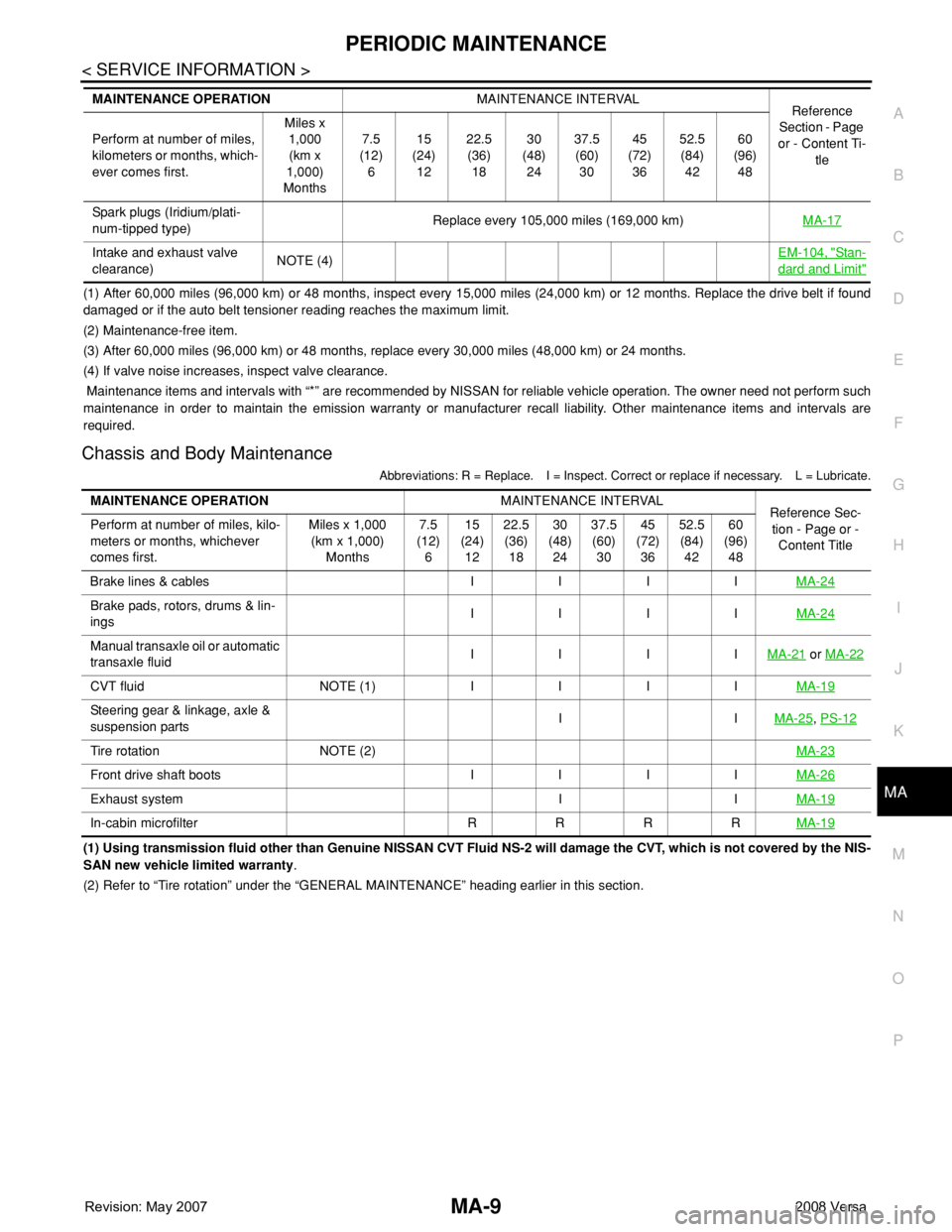
(1) After 60,000 miles (96,000 km) or 48 months, inspect every 15,000 miles (24,000 km) or 12 months. Replace the drive belt if found
damaged or if the auto belt tensioner reading reaches the maximum limit.
(2) Maintenance-free item.
(3) After 60,000 miles (96,000 km) or 48 months, replace every 30,000 miles (48,000 km) or 24 months.
(4) If valve noise increases, inspect valve clearance.
Maintenance items and intervals with “*” are recommended by NISSAN for reliable vehicle operation. The owner need not perform such
maintenance in order to maintain the emission warranty or manufacturer recall liability. Other maintenance items and intervals are
required.
Chassis and Body Maintenance
Abbreviations: R = Replace. I = Inspect. Correct or replace if necessary. L = Lubricate.
(1) Using transmission fluid other than Genuine NISSAN CVT Fluid NS-2 will damage the CVT, which is not covered by the NIS-
SAN new vehicle limited warranty.
(2) Refer to “Tire rotation” under the “GENERAL MAINTENANCE” heading earlier in this section. Spark plugs (Iridium/plati-
num-tipped type)Replace every 105,000 miles (169,000 km)MA-17
Intake and exhaust valve
clearance)NOTE (4)EM-104, "Sta n-
dard and Limit"
MAINTENANCE OPERATIONMAINTENANCE INTERVAL
Reference
Section - Page
or - Content Ti-
tle Perform at number of miles,
kilometers or months, which-
ever comes first.Miles x
1,000
(km x
1,000)
Months7.5
(12)
615
(24)
1222.5
(36)
1830
(48)
2437.5
(60)
3045
(72)
3652.5
(84)
4260
(96)
48
MAINTENANCE OPERATIONMAINTENANCE INTERVAL
Reference Sec-
tion - Page or -
Content Title Perform at number of miles, kilo-
meters or months, whichever
comes first.Miles x 1,000
(km x 1,000)
Months7.5
(12)
615
(24)
1222.5
(36)
1830
(48)
2437.5
(60)
3045
(72)
3652.5
(84)
4260
(96)
48
Brake lines & cables I I I IMA-24
Brake pads, rotors, drums & lin-
ings IIIIMA-24
Manual transaxle oil or automatic
transaxle fluidIIIIMA-21 or MA-22
CVT fluid NOTE (1) IIIIMA-19
Steering gear & linkage, axle &
suspension partsIIMA-25, PS-12
Tire rotation NOTE (2)MA-23
Front drive shaft boots I I I IMA-26
Exhaust system I IMA-19
In-cabin microfilter R R R RMA-19