Page 1483 of 2771

DTC P0850 PNP SWITCH
EC-409
< SERVICE INFORMATION >
C
D
E
F
G
H
I
J
K
L
MA
EC
N
P O
>>INSPECTION END
M/T MODELS
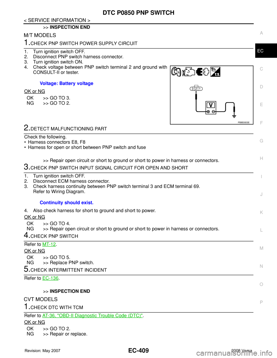
1.CHECK PNP SWITCH POWER SUPPLY CIRCUIT
1. Turn ignition switch OFF.
2. Disconnect PNP switch harness connector.
3. Turn ignition switch ON.
4. Check voltage between PNP switch terminal 2 and ground with
CONSULT-II or tester.
OK or NG
OK >> GO TO 3.
NG >> GO TO 2.
2.DETECT MALFUNCTIONING PART
Check the following.
• Harness connectors E8, F8
• Harness for open or short between PNP switch and fuse
>> Repair open circuit or short to ground or short to power in harness or connectors.
3.CHECK PNP SWITCH INPUT SIGNAL CIRCUIT FOR OPEN AND SHORT
1. Turn ignition switch OFF.
2. Disconnect ECM harness connector.
3. Check harness continuity between PNP switch terminal 3 and ECM terminal 69.
Refer to Wiring Diagram.
4. Also check harness for short to ground and short to power.
OK or NG
OK >> GO TO 4.
NG >> Repair open circuit or short to ground or short to power in harness or connectors.
4.CHECK PNP SWITCH
Refer to MT-12
.
OK or NG
OK >> GO TO 5.
NG >> Replace PNP switch.
5.CHECK INTERMITTENT INCIDENT
Refer to EC-136
.
>>INSPECTION END
CVT MODELS
1.CHECK DTC WITH TCM
Refer to AT-36, "
OBD-II Diagnostic Trouble Code (DTC)".
OK or NG
OK >> GO TO 2.
NG >> Repair or replace.Voltage: Battery voltage
PBIB3003E
Continuity should exist.
Page 1484 of 2771
EC-410
< SERVICE INFORMATION >
DTC P0850 PNP SWITCH
2.CHECK STARTING SYSTEM
Turn ignition switch OFF, then turn it to START.
Does starter motor operate?
Ye s o r N o
Ye s > > G O T O 3 .
No >> Refer to SC-8
.
3.CHECK PNP SWITCH INPUT SIGNAL CIRCUIT FOR OPEN AND SHORT-I
1. Turn ignition switch OFF.
2. Disconnect ECM and TCM harness connectors.
3. Check harness continuity between TCM terminal 24 and ECM terminal 69.
Refer to Wiring Diagram.
4. Also check harness for short to ground and short to power.
OK or NG
OK >> GO TO 5.
NG >> GO TO 4.
4.DETECT MALFUNCTIONING PART
Check the following.
• Harness connectors F8, E8
• Harness for open or short between TCM and ECM.
>> Repair open circuit or short to ground or short to power in harness or connectors.
5.CHECK INTERMITTENT INCIDENT
Refer to EC-136
.
>>INSPECTION END Continuity should exist.
Page 1490 of 2771
EC-416
< SERVICE INFORMATION >
DTC P1217 ENGINE OVER TEMPERATURE
Wiring Diagram
INFOID:0000000001702933
BBWA2997E
Page 1494 of 2771

EC-420
< SERVICE INFORMATION >
DTC P1217 ENGINE OVER TEMPERATURE
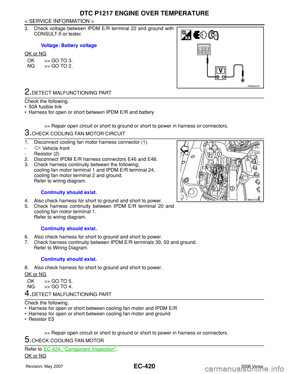
3. Check voltage between IPDM E/R terminal 22 and ground with
CONSULT-II or tester.
OK or NG
OK >> GO TO 3.
NG >> GO TO 2.
2.DETECT MALFUNCTIONING PART
Check the following.
• 50A fusible link
• Harness for open or short between IPDM E/R and battery
>> Repair open circuit or short to ground or short to power in harness or connectors.
3.CHECK COOLING FAN MOTOR CIRCUIT
1. Disconnect cooling fan motor harness connector (1).
- : Vehicle front
-Resistor (2)
2. Disconnect IPDM E/R harness connectors E46 and E48.
3. Check harness continuity between the following;
cooling fan motor terminal 1 and IPDM E/R terminal 24,
cooling fan motor terminal 2 and ground.
Refer to wiring diagram.
4. Also check harness for short to ground and short to power.
5. Check harness continuity between IPDM E/R terminal 20 and
cooling fan motor terminal 1.
Refer to wiring diagram.
6. Also check harness for short to ground and short to power.
7. Check harness continuity between IPDM E/R terminals 39, 59 and ground.
Refer to Wiring Diagram.
8. Also check harness for short to ground and short to power.
OK or NG
OK >> GO TO 5.
NG >> GO TO 4.
4.DETECT MALFUNCTIONING PART
Check the following.
• Harness for open or short between cooling fan motor and IPDM E/R
• Harness for open or short between cooling fan motor and ground
•Resistor E5
>> Repair open circuit or short to ground or short to power in harness or connectors.
5.CHECK COOLING FAN MOTOR
Refer to EC-424, "
Component Inspection".
OK or NG
Voltage: Battery voltage
PBIB2607E
Continuity should exist.
Continuity should exist.
Continuity should exist.
BBIA0706E
Page 1497 of 2771

DTC P1217 ENGINE OVER TEMPERATURE
EC-423
< SERVICE INFORMATION >
C
D
E
F
G
H
I
J
K
L
MA
EC
N
P O
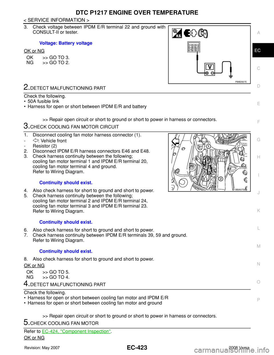
3. Check voltage between IPDM E/R terminal 22 and ground with
CONSULT-II or tester.
OK or NG
OK >> GO TO 3.
NG >> GO TO 2.
2.DETECT MALFUNCTIONING PART
Check the following.
• 50A fusible link
• Harness for open or short between IPDM E/R and battery
>> Repair open circuit or short to ground or short to power in harness or connectors.
3.CHECK COOLING FAN MOTOR CIRCUIT
1. Disconnect cooling fan motor harness connector (1).
- : Vehicle front
-Resistor (2)
2. Disconnect IPDM E/R harness connectors E46 and E48.
3. Check harness continuity between the following;
cooling fan motor terminal 1 and IPDM E/R terminal 20,
cooling fan motor terminal 4 and ground.
Refer to Wiring Diagram.
4. Also check harness for short to ground and short to power.
5. Check harness continuity between the following;
cooling fan motor terminal 2 and IPDM E/R terminal 24,
cooling fan motor terminal 3 and IPDM E/R terminal 23.
Refer to Wiring Diagram.
6. Also check harness for short to ground and short to power.
7. Check harness continuity between IPDM E/R terminals 39, 59 and ground.
Refer to Wiring Diagram.
8. Also check harness for short to ground and short to power.
OK or NG
OK >> GO TO 5.
NG >> GO TO 4.
4.DETECT MALFUNCTIONING PART
Check the following.
• Harness for open or short between cooling fan motor and IPDM E/R
• Harness for open or short between cooling fan motor and ground
>> Repair open circuit or short to ground or short to power in harness or connectors.
5.CHECK COOLING FAN MOTOR
Refer to EC-424, "
Component Inspection".
OK or NG
Voltage: Battery voltage
PBIB2607E
Continuity should exist.
Continuity should exist.
Continuity should exist.
BBIA0706E
Page 1508 of 2771
EC-434
< SERVICE INFORMATION >
DTC P1564 ASCD STEERING SWITCH
Wiring Diagram
INFOID:0000000001702955
Specification data are reference values and are measured between each terminal and ground.
CAUTION:
Do not use ECM ground terminals when measuring input/output voltage. Doing so may result in dam-
age to the ECM's transistor. Use a ground other than ECM terminals, such as the ground.
BBWA2663E
Page 1510 of 2771

EC-436
< SERVICE INFORMATION >
DTC P1564 ASCD STEERING SWITCH
Without CONSULT-II
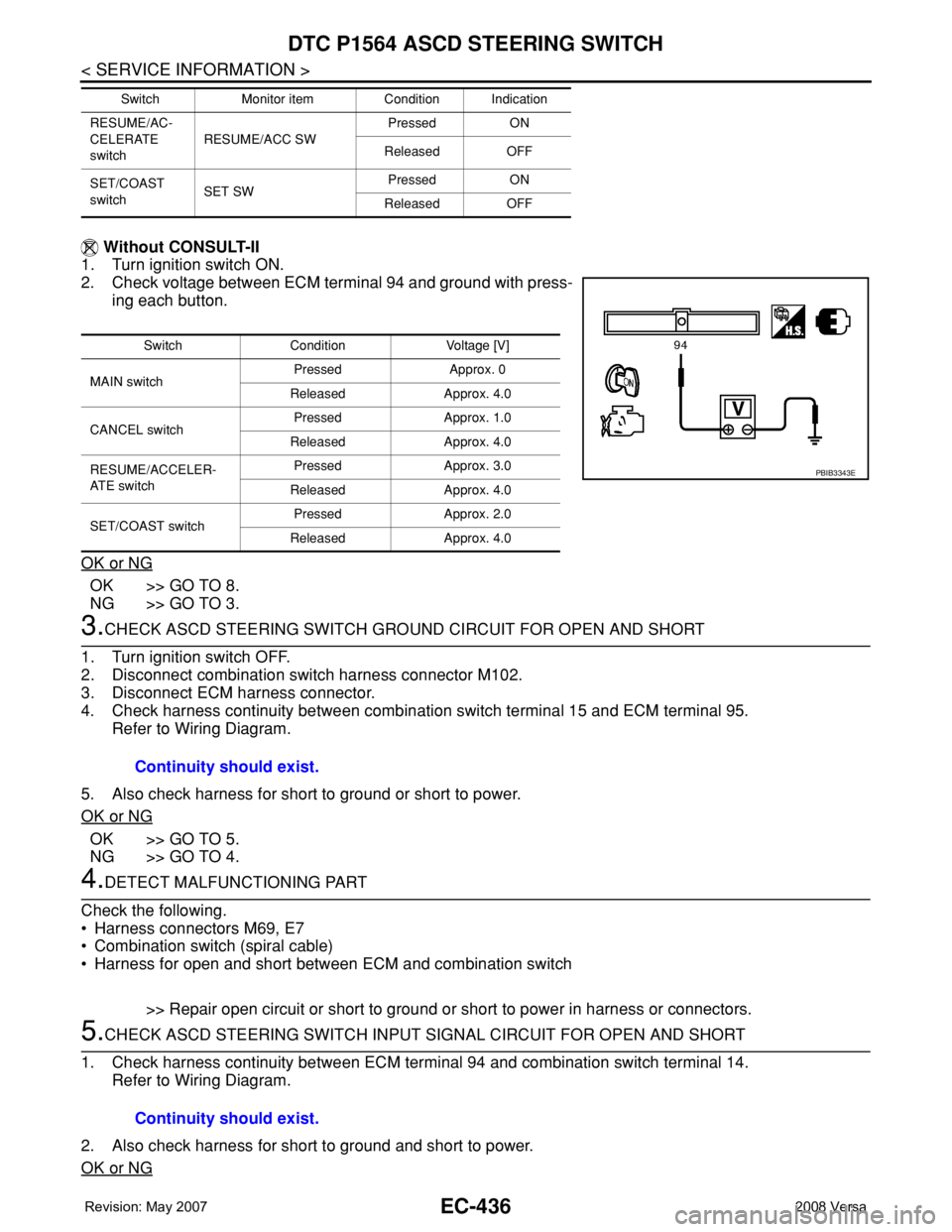
1. Turn ignition switch ON.
2. Check voltage between ECM terminal 94 and ground with press-
ing each button.
OK or NG
OK >> GO TO 8.
NG >> GO TO 3.
3.CHECK ASCD STEERING SWITCH GROUND CIRCUIT FOR OPEN AND SHORT
1. Turn ignition switch OFF.
2. Disconnect combination switch harness connector M102.
3. Disconnect ECM harness connector.
4. Check harness continuity between combination switch terminal 15 and ECM terminal 95.
Refer to Wiring Diagram.
5. Also check harness for short to ground or short to power.
OK or NG
OK >> GO TO 5.
NG >> GO TO 4.
4.DETECT MALFUNCTIONING PART
Check the following.
• Harness connectors M69, E7
• Combination switch (spiral cable)
• Harness for open and short between ECM and combination switch
>> Repair open circuit or short to ground or short to power in harness or connectors.
5.CHECK ASCD STEERING SWITCH INPUT SIGNAL CIRCUIT FOR OPEN AND SHORT
1. Check harness continuity between ECM terminal 94 and combination switch terminal 14.
Refer to Wiring Diagram.
2. Also check harness for short to ground and short to power.
OK or NG
RESUME/AC-
CELERATE
switchRESUME/ACC SWPressed ON
Released OFF
SET/COAST
switchSET SWPressed ON
Released OFF Switch Monitor item Condition Indication
Switch Condition Voltage [V]
MAIN switchPressed Approx. 0
Released Approx. 4.0
CANCEL switchPressed Approx. 1.0
Released Approx. 4.0
RESUME/ACCELER-
AT E s w i t c hPressed Approx. 3.0
Released Approx. 4.0
SET/COAST switchPressed Approx. 2.0
Released Approx. 4.0
PBIB3343E
Continuity should exist.
Continuity should exist.
Page 1514 of 2771
EC-440
< SERVICE INFORMATION >
DTC P1572 ASCD BRAKE SWITCH
Wiring Diagram
INFOID:0000000001702962
Specification data are reference values and are measured between each terminal and ground.
CAUTION:
Do not use ECM ground terminals when measuring input/output voltage. Doing so may result in dam-
age to the ECM's transistor. Use a ground other than ECM terminals, such as the ground.
BBWA2665E