2008 NISSAN LATIO gas type
[x] Cancel search: gas typePage 1709 of 2771
EM-32
< SERVICE INFORMATION >
IGNITION COIL, SPARK PLUG AND ROCKER COVER
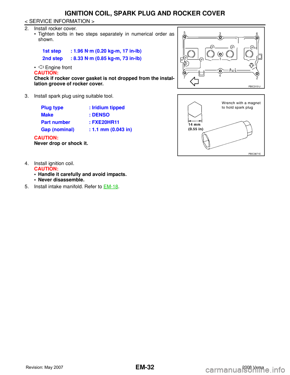
2. Install rocker cover.
• Tighten bolts in two steps separately in numerical order as
shown.
• Engine front
CAUTION:
Check if rocker cover gasket is not dropped from the instal-
lation groove of rocker cover.
3. Install spark plug using suitable tool.
CAUTION:
Never drop or shock it.
4. Install ignition coil.
CAUTION:
• Handle it carefully and avoid impacts.
• Never disassemble.
5. Install intake manifold. Refer to EM-18
. 1st step : 1.96 N·m (0.20 kg-m, 17 in-lb)
2nd step : 8.33 N·m (0.85 kg-m, 73 in-lb)
PBIC3151J
Plug type : Iridium tipped
Make : DENSO
Part number : FXE20HR11
Gap (nominal) : 1.1 mm (0.043 in)
PBIC3871E
Page 1717 of 2771
EM-40
< SERVICE INFORMATION >
TIMING CHAIN
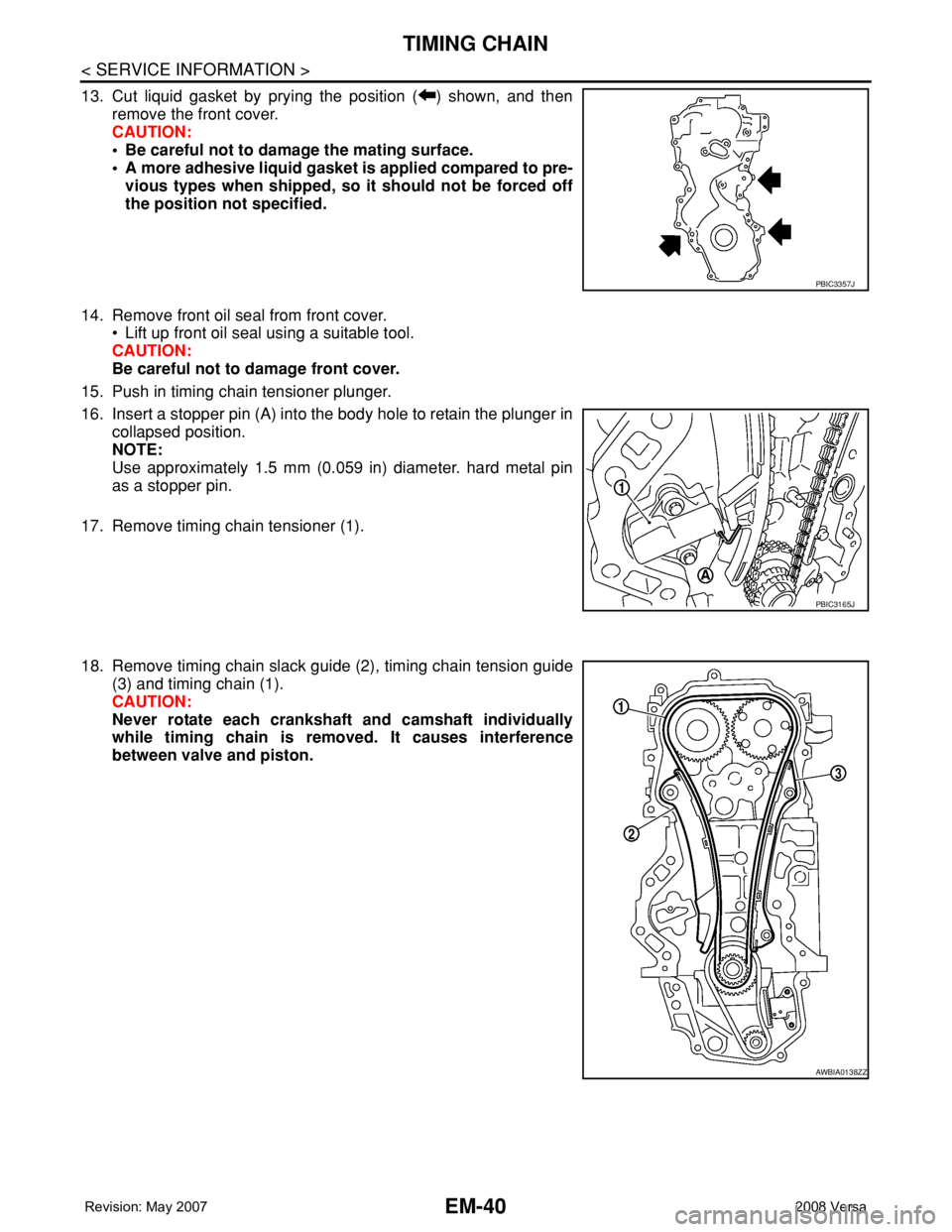
13. Cut liquid gasket by prying the position ( ) shown, and then
remove the front cover.
CAUTION:
• Be careful not to damage the mating surface.
• A more adhesive liquid gasket is applied compared to pre-
vious types when shipped, so it should not be forced off
the position not specified.
14. Remove front oil seal from front cover.
• Lift up front oil seal using a suitable tool.
CAUTION:
Be careful not to damage front cover.
15. Push in timing chain tensioner plunger.
16. Insert a stopper pin (A) into the body hole to retain the plunger in
collapsed position.
NOTE:
Use approximately 1.5 mm (0.059 in) diameter. hard metal pin
as a stopper pin.
17. Remove timing chain tensioner (1).
18. Remove timing chain slack guide (2), timing chain tension guide
(3) and timing chain (1).
CAUTION:
Never rotate each crankshaft and camshaft individually
while timing chain is removed. It causes interference
between valve and piston.
PBIC3357J
PBIC3165J
AWBIA0138ZZ
Page 1725 of 2771
EM-48
< SERVICE INFORMATION >
CAMSHAFT
• Fuel tube and fuel injector assembly; Refer to EM-33.
• Front cover, timing chain and related parts; Refer to EM-37
.
7. Remove camshaft position sensor (PHASE) from camshaft bracket.
CAUTION:
• Handle carefully to avoid dropping and shocks.
• Never disassemble.
• Never allow metal powder to adhere to magnetic part at sensor tip.
• Never place sensor in a location where it is exposed to magnetism.
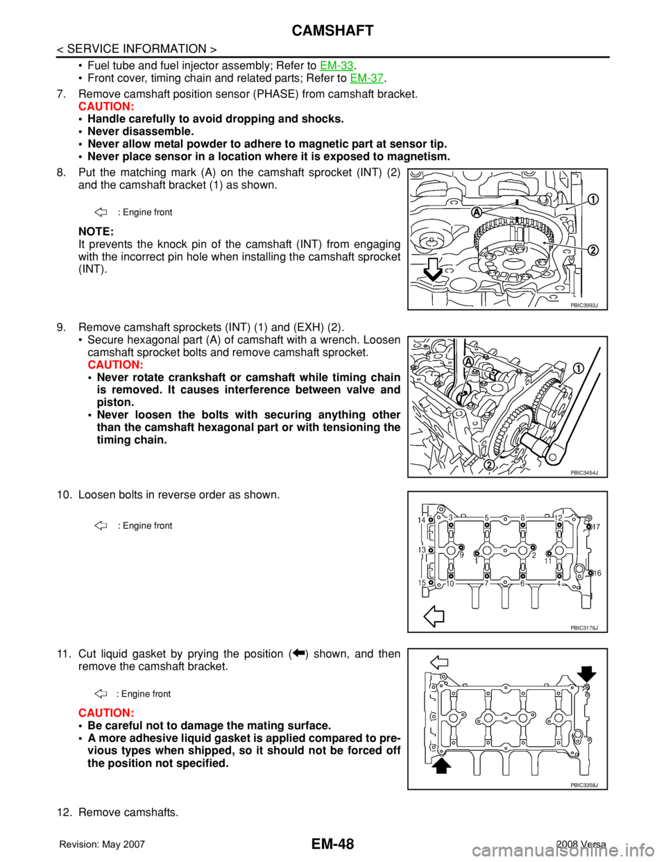
8. Put the matching mark (A) on the camshaft sprocket (INT) (2)
and the camshaft bracket (1) as shown.
NOTE:
It prevents the knock pin of the camshaft (INT) from engaging
with the incorrect pin hole when installing the camshaft sprocket
(INT).
9. Remove camshaft sprockets (INT) (1) and (EXH) (2).
• Secure hexagonal part (A) of camshaft with a wrench. Loosen
camshaft sprocket bolts and remove camshaft sprocket.
CAUTION:
• Never rotate crankshaft or camshaft while timing chain
is removed. It causes interference between valve and
piston.
• Never loosen the bolts with securing anything other
than the camshaft hexagonal part or with tensioning the
timing chain.
10. Loosen bolts in reverse order as shown.
11. Cut liquid gasket by prying the position ( ) shown, and then
remove the camshaft bracket.
CAUTION:
• Be careful not to damage the mating surface.
• A more adhesive liquid gasket is applied compared to pre-
vious types when shipped, so it should not be forced off
the position not specified.
12. Remove camshafts.
: Engine front
PBIC3992J
PBIC3454J
: Engine front
PBIC3176J
: Engine front
PBIC3358J
Page 1904 of 2771
PRECAUTIONS
GW-3
< SERVICE INFORMATION >
C
D
E
F
G
H
J
K
L
MA
B
GW
N
O
P
SERVICE INFORMATION
PRECAUTIONS
Precaution for Supplemental Restraint System (SRS) "AIR BAG" and "SEAT BELT
PRE-TENSIONER"
INFOID:0000000001704128
The Supplemental Restraint System such as “AIR BAG” and “SEAT BELT PRE-TENSIONER”, used along
with a front seat belt, helps to reduce the risk or severity of injury to the driver and front passenger for certain
types of collision. This system includes seat belt switch inputs and dual stage front air bag modules. The SRS
system uses the seat belt switches to determine the front air bag deployment, and may only deploy one front
air bag, depending on the severity of a collision and whether the front occupants are belted or unbelted.
Information necessary to service the system safely is included in the SRS and SB section of this Service Man-
ual.
WARNING:
• To avoid rendering the SRS inoperative, which could increase the risk of personal injury or death in
the event of a collision which would result in air bag inflation, all maintenance must be performed by
an authorized NISSAN/INFINITI dealer.
• Improper maintenance, including incorrect removal and installation of the SRS, can lead to personal
injury caused by unintentional activation of the system. For removal of Spiral Cable and Air Bag
Module, see the SRS section.
• Do not use electrical test equipment on any circuit related to the SRS unless instructed to in this
Service Manual. SRS wiring harnesses can be identified by yellow and/or orange harnesses or har-
ness connectors.
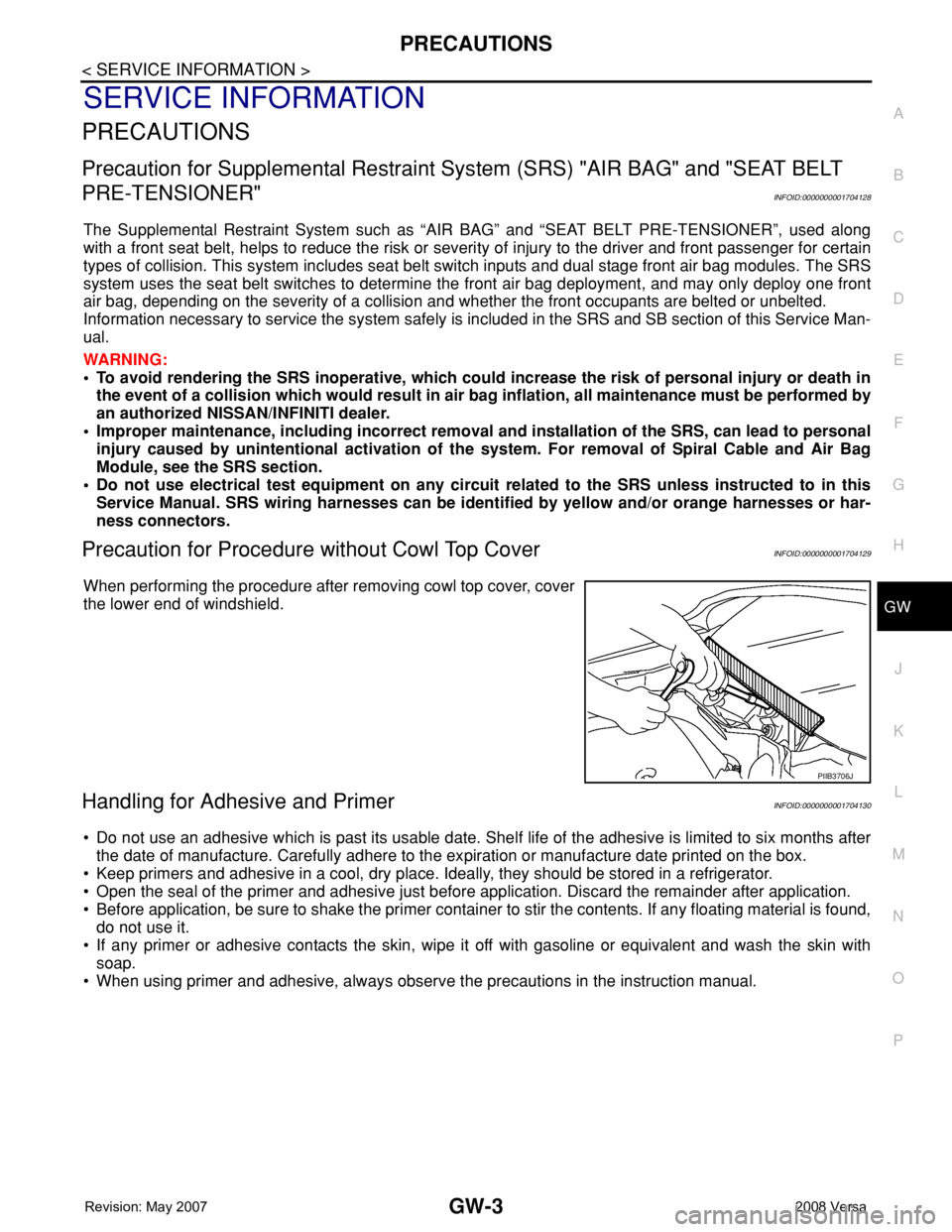
Precaution for Procedure without Cowl Top CoverINFOID:0000000001704129
When performing the procedure after removing cowl top cover, cover
the lower end of windshield.
Handling for Adhesive and PrimerINFOID:0000000001704130
• Do not use an adhesive which is past its usable date. Shelf life of the adhesive is limited to six months after
the date of manufacture. Carefully adhere to the expiration or manufacture date printed on the box.
• Keep primers and adhesive in a cool, dry place. Ideally, they should be stored in a refrigerator.
• Open the seal of the primer and adhesive just before application. Discard the remainder after application.
• Before application, be sure to shake the primer container to stir the contents. If any floating material is found,
do not use it.
• If any primer or adhesive contacts the skin, wipe it off with gasoline or equivalent and wash the skin with
soap.
• When using primer and adhesive, always observe the precautions in the instruction manual.
PIIB3706J
Page 2252 of 2771
LU-2
< SERVICE INFORMATION >
PRECAUTIONS
SERVICE INFORMATION
PRECAUTIONS
Precaution for Supplemental Restraint System (SRS) "AIR BAG" and "SEAT BELT
PRE-TENSIONER"
INFOID:0000000001790697
The Supplemental Restraint System such as “AIR BAG” and “SEAT BELT PRE-TENSIONER”, used along
with a front seat belt, helps to reduce the risk or severity of injury to the driver and front passenger for certain
types of collision. This system includes seat belt switch inputs and dual stage front air bag modules. The SRS
system uses the seat belt switches to determine the front air bag deployment, and may only deploy one front
air bag, depending on the severity of a collision and whether the front occupants are belted or unbelted.
Information necessary to service the system safely is included in the SRS and SB section of this Service Man-
ual.
WARNING:
• To avoid rendering the SRS inoperative, which could increase the risk of personal injury or death in
the event of a collision which would result in air bag inflation, all maintenance must be performed by
an authorized NISSAN/INFINITI dealer.
• Improper maintenance, including incorrect removal and installation of the SRS, can lead to personal
injury caused by unintentional activation of the system. For removal of Spiral Cable and Air Bag
Module, see the SRS section.
• Do not use electrical test equipment on any circuit related to the SRS unless instructed to in this
Service Manual. SRS wiring harnesses can be identified by yellow and/or orange harnesses or har-
ness connectors.
Precaution for Liquid GasketINFOID:0000000001702514
LIQUID GASKET APPLICATION PROCEDURE
1. Remove old liquid gasket adhering to the liquid gasket application surface and the mating surface.
• Remove liquid gasket completely from the liquid gasket application surface, bolts, and bolt holes.
2. Wipe the liquid gasket application surface and the mating surface with white gasoline (lighting and heating
use) to remove adhering moisture, grease and foreign materials.
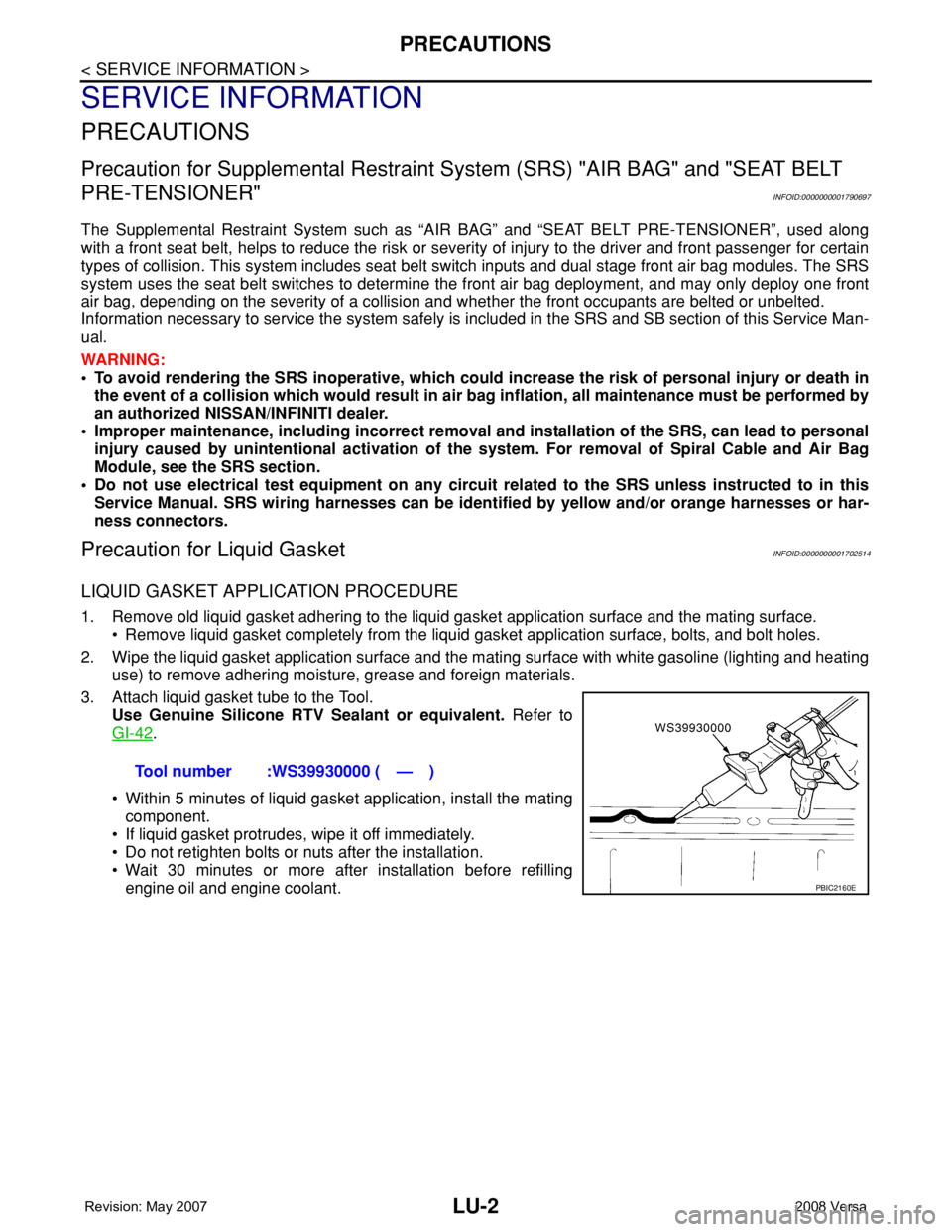
3. Attach liquid gasket tube to the Tool.
Use Genuine Silicone RTV Sealant or equivalent. Refer to
GI-42
.
• Within 5 minutes of liquid gasket application, install the mating
component.
• If liquid gasket protrudes, wipe it off immediately.
• Do not retighten bolts or nuts after the installation.
• Wait 30 minutes or more after installation before refilling
engine oil and engine coolant.Tool number :WS39930000 ( — )
PBIC2160E
Page 2270 of 2771

MA-10
< SERVICE INFORMATION >
RECOMMENDED FLUIDS AND LUBRICANTS
RECOMMENDED FLUIDS AND LUBRICANTS
Fluids and LubricantsINFOID:0000000001704725
*1: For further details, see “Engine Oil Recommendation”.
*2: DEXRON
TM III / MERCONTM , or equivalent may also be used. Outside the continental United States and Alaska contact a NISSAN
dealership for more information regarding suitable fluids, including recommended brand(s) of DEXRONTM III / MERCONTM Automatic
Transmission Fluid.
*3: Using transaxle fluid other than Genuine NISSAN CVT Fluid NS-2 will damage the CVT, which is not covered by the NISSAN
new vehicle limited warranty.
*4: Available in mainland U.S.A. through your NISSAN dealer.
*5: For further details, see “Air conditioner specification label”.
SAE Viscosity NumberINFOID:0000000001704726
NISSAN recommends the use of an energy conserving oil in order to improve fuel economy.
Select only engine oils that meet the American Petroleum Institute (API) certification and International Lubrica-
tion Standardization and Approval Committee (ILSAC) certification and SAE viscosity standard. These oils
have the API certification mark on the front of the container. Oils which do not have the specified quality label
should not be used as they could cause engine damage.
DescriptionCapacity (Approximate)
Recommended Fluids/Lubricants
Liter US measure Imp measure
Fuel 52.0 13 3/4 gal 11 1/2 galUnleaded gasoline with an octane rating of
at least 87 AKI (RON 91)
Engine oil
Drain and refillWith oil filter
change3.9 4 1/8 qt 3 3/8 qt
• Engine oil with API Certification Mark *1
• Viscosity SAE 5W-30 Without oil filter
change3.7 3 7/8 qt 3 1/4 qt
Dry engine (engine overhaul) 4.9 5 1/8 qt 4 3/8 qt
Cooling system
(with reservoir at max level)6.8 7 1/4 qt 6 qtGenuine NISSAN Long Life Anti-freeze
Coolant or equivalent
Manual transaxle fluid (MTF) 2.0 4 1/4 pt 3 1/2 ptEFF XT4447 M+ 75W-80 or API GL-4, Vis-
cosity SAE 75W-80
Automatic transaxle fluid (ATF) 7.9 8 3/8 qt 7 qtGenuine NISSAN Matic “D” ATF (Continen-
tal U.S. and Alaska) or Canada NISSAN
Automatic Transmission Fluid *2
CVT fluid 8.3 8 3/4 qt 7 1/4 qt Genuine NISSAN CVT Fluid NS-2 *3
Brake and clutch fluid — — —Genuine NISSAN Super Heavy Duty Brake
Fluid*4 or equivalent DOT 3 (US FMVSS
No. 116)
Multi-purpose grease — — — NLGI No. 2 (Lithium soap base)
Windshield washer fluid 4.5 4 3/4 qt 4 qtGenuine NISSAN Windshield Washer Con-
centrate Cleaner & Anti-Freeze or equiva-
lent
Air conditioning system refrigerant 0.45 ± 0.05 kg 0.99 ± 0.11 lb 0.99 ± 0.11 lb HFC-134a (R-134a) *5
Air conditioning
system oilTyp e 1
120 m4.1 fl oz 4.2 fl ozNISSAN A/C System Lubricant Type R or
equivalent *5
Typ e 2
100 m3.4 fl oz 3.5 fl ozNISSAN A/C System Lubricant Type S or
equivalent *5
Page 2283 of 2771
CHASSIS AND BODY MAINTENANCE
MA-23
< SERVICE INFORMATION >
C
D
E
F
G
H
I
J
K
MA
B
MA
N
O
P
2. Stop engine.
3. Drain A/T fluid by removing the drain plug. Reinstall the drain plug to the specified torque.
CAUTION:
Do not reuse drain plug gasket.
4. Refill the transaxle with new specified A/T fluid through the A/T fluid charging pipe. Always refill the tran-
saxle with the same volume of A/T fluid that was drained out.
5. Run engine at idle speed for 5 minutes.
6. Check A/T fluid level and condition. Refer to MA-22, "
Checking A/T Fluid" .
Balancing WheelsINFOID:0000000001704749
Adjust wheel balance using road wheel center.
CAUTION:
• Be careful not to scratch the road wheel during removal.
• Use clip-on type wheel balance weights only.
Wheel balance (Maximum allowable unbalance):
RotationINFOID:0000000001704750
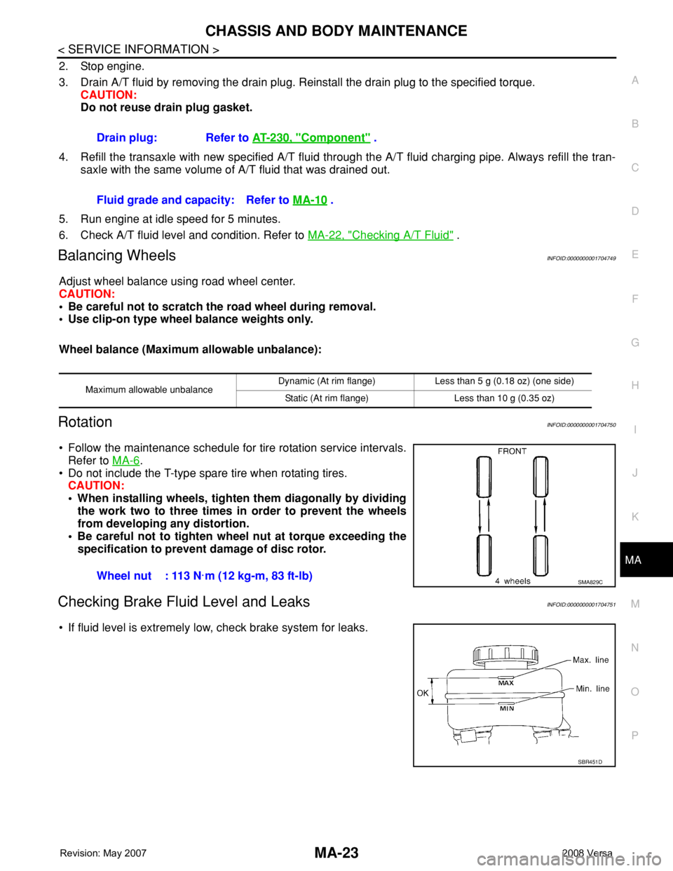
• Follow the maintenance schedule for tire rotation service intervals.
Refer to MA-6
.
• Do not include the T-type spare tire when rotating tires.
CAUTION:
• When installing wheels, tighten them diagonally by dividing
the work two to three times in order to prevent the wheels
from developing any distortion.
• Be careful not to tighten wheel nut at torque exceeding the
specification to prevent damage of disc rotor.
Checking Brake Fluid Level and LeaksINFOID:0000000001704751
• If fluid level is extremely low, check brake system for leaks.Drain plug: Refer to AT-230, "
Component" .
Fluid grade and capacity: Refer to MA-10
.
Maximum allowable unbalanceDynamic (At rim flange) Less than 5 g (0.18 oz) (one side)
Static (At rim flange) Less than 10 g (0.35 oz)
Wheel nut : 113 N·m (12 kg-m, 83 ft-lb)SMA829C
SBR451D
Page 2342 of 2771

MTC-4
< SERVICE INFORMATION >
PRECAUTIONS
- Do not allow A/C oil to come in contact with styrofoam parts. Damage may result.
General Refrigerant PrecautionINFOID:0000000001704277
WARNING:
• Avoid breathing A/C refrigerant and oil vapor or mist. Exposure may irritate eyes, nose and throat.
Use only approved recovery/recycling equipment to discharge HFC-134a (R-134a) refrigerant. If acci-
dental system discharge occurs, ventilate work area before resuming service. Additional health and
safety information may be obtained from refrigerant and oil manufacturers.
• Do not release refrigerant into the air. Use approved recovery/recycling equipment to capture the
refrigerant every time an air conditioning system is discharged.
• Always wear eye and hand protection (goggles and gloves) when working with any refrigerant or air
conditioning system.
• Do not store or heat refrigerant containers above 52°C (126° F).
• Do not heat a refrigerant container with an open flame; if container warming is required, place the
bottom of the container in a warm pail of water.
• Do not intentionally drop, puncture, or incinerate refrigerant containers.
• Keep refrigerant away from open flames: poisonous gas will be produced if refrigerant burns.
• Refrigerant will displace oxygen, therefore be certain to work in well ventilated areas to prevent suf-
focation.
• Do not pressure test or leak test HFC-134a (R-134a) service equipment and/or vehicle air condition-
ing systems with compressed air during repair. Some mixtures of air and HFC-134a (R-134a) have
been shown to be combustible at elevated pressures. These mixtures, if ignited, may cause injury or
property damage. Additional health and safety information may be obtained from refrigerant manu-
facturers.
Oil PrecautionINFOID:0000000001704278
• Use only specified oil for the HFC-134a (R-134a) A/C system and HFC-134a (R-134a) components. If oil
other than that specified is used, compressor malfunction is likely to occur.
• The specified HFC-134a (R-134a) oil rapidly absorbs moisture from the atmosphere. The following handling
precautions must be observed:
- When removing refrigerant components from a vehicle, immediately cap (seal) the component to minimize
the entry of moisture from the atmosphere.
- When installing refrigerant components to a vehicle, do not remove the caps (unseal) until just before con-
necting the components. Connect all refrigerant loop components as quickly as possible to minimize the
entry of moisture into system.
- Only use the specified oil from a sealed container. Immediately reseal containers of oil. Without proper seal-
ing, oil will become moisture saturated and should not be used.
• Avoid breathing A/C refrigerant and oil vapor or mist. Exposure may irritate eyes, nose and throat.
Use only approved recovery/recycling equipment to discharge HFC-134a (R-134a) refrigerant. If accidental
system discharge occurs, ventilate work area before resuming service. Additional health and safety informa-
tion may be obtained from refrigerant and oil manufacturers.
• Do not allow A/C oil to come in contact with styrofoam parts. Damage may result.
Precaution for Refrigerant ConnectionINFOID:0000000001704279
A new type refrigerant connection has been introduced to all refrigerant lines except the following location.
• Expansion valve to evaporator
• Refrigerant pressure sensor to condenser