2008 NISSAN LATIO coolant level
[x] Cancel search: coolant levelPage 1344 of 2771
 is used to detect the fuel tem-
perature insi")
EC-270
< SERVICE INFORMATION >
DTC P0181 FTT SENSOR
DTC P0181 FTT SENSOR
Component DescriptionINFOID:0000000001702768
The fuel tank temperature sensor (4) is used to detect the fuel tem-
perature inside the fuel tank. The sensor modifies a voltage signal
from the ECM. The modified signal returns to the ECM as the fuel
temperature input. The sensor uses a thermistor which is sensitive to
the change in temperature. The electrical resistance of the ther-
mistor decreases as temperature increases.
• Fuel level sensor unit and fuel pump (1)
• Fuel pressure regulator (2)
• Fuel level sensor (3)
*: This data is reference values and is measured between ECM terminal 43 (Fuel
tank temperature sensor) and ground.
CAUTION:
Do not use ECM ground terminals when measuring input/output
voltage. Doing so may result damage the ECM's transistor. Use
ground other than ECM, such as ground.
On Board Diagnosis LogicINFOID:0000000001702769
DTC Confirmation ProcedureINFOID:0000000001702770
NOTE:
If DTC Confirmation Procedure has been previously conducted, always turn ignition switch OFF and wait at
least 10 seconds before conducting the next test.
WITH CONSULT-II
1. Turn ignition switch ON.
2. Select “DATA MONITOR” mode with CONSULT-II.
3. Wait at least 10 seconds.
If the result is NG, go to EC-271, "
Diagnosis Procedure".
If the result is OK, go to following step.
4. Check “COOLAN TEMP/S” value.
If the “COOLAN TEMP/S” is less than 60°C (140°F), the result
will be OK.
If the “COOLAN TEMP/S” is above 60°C (140°F), go to the fol-
lowing step.
5. Cool engine down until “COOLAN TEMP/S” signal is less than
60°C (140°F).
6. Wait at least 10 seconds.
7. If 1st trip DTC is detected, go to EC-271, "
Diagnosis Procedure".
BBIA0704E
Fluid temperature
°C (°F)Voltage*
VResistance
kΩ
20 (68) 3.5 2.3 - 2.7
50 (122) 2.2 0.79 - 0.90
SEF012P
DTC No. Trouble diagnosis name DTC detecting condition Possible cause
P0181
0181Fuel tank temperature
sensor circuit range/per-
formanceRationally incorrect voltage from the sensor is
sent to ECM, compared with the voltage signals
from engine coolant temperature sensor and in-
take air temperature sensor.• Harness or connectors
(Fuel tank temperature sensor circuit is
open or shorted)
• Fuel tank temperature sensor
SEF174Y
Page 1487 of 2771

DTC P1217 ENGINE OVER TEMPERATURE
EC-413
< SERVICE INFORMATION >
C
D
E
F
G
H
I
J
K
L
MA
EC
N
P O Cooling Fan Relay Operation
The ECM controls cooling fan relays in the IPDM E/R through CAN communication line.
CONSULT-II Reference Value in Data Monitor ModeINFOID:0000000001702930
Specification data are reference values.
On Board Diagnosis LogicINFOID:0000000001702931
If the cooling fan or another component in the cooling system malfunctions, engine coolant temperature will
rise. When the engine coolant temperature reaches an abnormally high temperature condition, a malfunction
is indicated.
This self-diagnosis has the one trip detection logic.
CAUTION:
When a malfunction is indicated, be sure to replace the coolant. Refer to CO-8, "
Changing Engine
Coolant". Also, replace the engine oil. Refer to LU-7, "Changing Engine Oil".
1. Fill radiator with coolant up to specified level with a filling speed of 2 liters per minute. Be sure to
use coolant with the proper mixture ratio. Refer to MA-11, "
Anti-freeze Coolant Mixture Ratio".
2. After refilling coolant, run engine to ensure that no water-flow noise is emitted.
Overall Function CheckINFOID:0000000001702932
Use this procedure to check the overall function of the cooling fan. During this check, a DTC might not be con-
firmed.
WARNING:
Cooling fan speedCooling fan relay
123
Stop (OFF) OFF OFF OFF
Low (LOW) ON OFF OFF
High (HI) OFF ON ON
MONITOR ITEM CONDITION SPECIFICATION
AIR COND SIG• Engine: After warming up, idle
the engineAir conditioner switch: OFF OFF
Air conditioner switch: ON
(Compressor operates.)ON
COOLING FAN• Engine: After warming up, idle
the engine
• Air conditioner switch: OFFEngine coolant temperature: 97°C
(207°F) or lessOFF
Engine coolant temperature: Between
98°C (208°F) and 99°C (210°F) or
moreLOW
Engine coolant temperature: 100°C
(212°F) or moreHIGH
DTC No. Trouble diagnosis name DTC detecting condition Possible cause
P1217
1217Engine over temperature
(Overheat)• Cooling fan does not operate properly (Over-
heat).
• Cooling fan system does not operate properly
(Overheat).
• Engine coolant was not added to the system
using the proper filling method.
• Engine coolant is not within the specified
range.• Harness or connectors
(Cooling fan circuit is open or shorted.)
• Cooling fan
• IPDM E/R (Cooling fan relays)
•Radiator hose
•Radiator
• Reservoir tank
•Radiator cap
• Water pump
•Thermostat
• Water control valve
For more information, refer to EC-424,
"Main 13 Causes of Overheating".
Page 1488 of 2771

EC-414
< SERVICE INFORMATION >
DTC P1217 ENGINE OVER TEMPERATURE
Never remove the radiator cap when the engine is hot. Serious burns could be caused by high pres-
sure fluid escaping from the reservoir tank or the radiator.
Wrap a thick cloth around cap. Carefully remove the cap by turning it a quarter turn to allow built-up
pressure to escape. Then turn the cap all the way off.
WITH CONSULT-II
1. Check the coolant level in the reservoir tank and radiator.
Allow engine to cool before checking coolant level.
If the coolant level in the reservoir tank and/or radiator is below
the proper range, skip the following steps and go to EC-417,
"Diagnosis Procedure" or EC-417, "Diagnosis Procedure".
2. Confirm whether customer filled the coolant or not. If customer
filled the coolant, skip the following steps and go to EC-417,
"Diagnosis Procedure" or EC-417, "Diagnosis Procedure".
3. Turn ignition switch ON.
4. Perform “COOLING FAN” in “ACTIVE TEST” mode with CON-
SULT-II.
5. If the results are NG, go to EC-417, "
Diagnosis Procedure" or
EC-417, "
Diagnosis Procedure".
WITH GST
Models with A/C
1. Check the coolant level in the reservoir tank and radiator.
Allow engine to cool before checking coolant level.
If the coolant level in the reservoir tank and/or radiator is below
the proper range, skip the following steps and go to EC-417,
"Diagnosis Procedure".
2. Confirm whether customer filled the coolant or not. If customer
filled the coolant, skip the following steps and go to EC-417,
"Diagnosis Procedure".
3. Start engine.
CAUTION:
Be careful not to overheat engine.
4. Set temperature control switch to full cold position.
5. Turn air conditioner switch ON.
6. Turn blower fan switch ON.
7. Run engine at idle for a few minutes with air conditioner operating.
CAUTION:
Be careful not to overheat engine.
SEF621W
SEF646X
SEF621W
Page 1489 of 2771
DTC P1217 ENGINE OVER TEMPERATURE
EC-415
< SERVICE INFORMATION >
C
D
E
F
G
H
I
J
K
L
MA
EC
N
P O
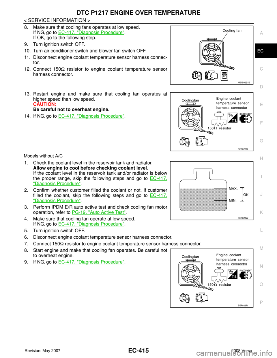
8. Make sure that cooling fans operates at low speed.
If NG, go to EC-417, "
Diagnosis Procedure".
If OK, go to the following step.
9. Turn ignition switch OFF.
10. Turn air conditioner switch and blower fan switch OFF.
11. Disconnect engine coolant temperature sensor harness connec-
tor.
12. Connect 150Ω resistor to engine coolant temperature sensor
harness connector.
13. Restart engine and make sure that cooling fan operates at
higher speed than low speed.
CAUTION:
Be careful not to overheat engine.
14. If NG, go to EC-417, "
Diagnosis Procedure".
Models without A/C
1. Check the coolant level in the reservoir tank and radiator.
Allow engine to cool before checking coolant level.
If the coolant level in the reservoir tank and/or radiator is below
the proper range, skip the following steps and go to EC-417,
"Diagnosis Procedure".
2. Confirm whether customer filled the coolant or not. If customer
filled the coolant, skip the following steps and go to EC-417,
"Diagnosis Procedure".
3. Perform IPDM E/R auto active test and check cooling fan motor
operation, refer to PG-19, "
Auto Active Test".
4. Make sure that cooling fan operate at low speed.
If NG, go to EC-417, "
Diagnosis Procedure".
5. Turn ignition switch OFF.
6. Disconnect engine coolant temperature sensor harness connector.
7. Connect 150Ω resistor to engine coolant temperature sensor harness connector.
8. Start engine and make that cooling fan operates. Be careful not
to overheat engine.
9. If NG, go to EC-417, "
Diagnosis Procedure".
MBIB0651E
SEF023R
SEF621W
SEF023R
Page 1498 of 2771

EC-424
< SERVICE INFORMATION >
DTC P1217 ENGINE OVER TEMPERATURE
OK >> GO TO 6.
NG >> Replace cooling fan motor.
6.CHECK INTERMITTENT INCIDENT
Perform EC-136
.
OK or NG
OK >> Replace IPDM E/R. Refer to PG-26, "Removal and Installation of IPDM E/R".
NG >> Repair or replace harness or connector.
Main 13 Causes of OverheatingINFOID:0000000001702935
*1: Turn the ignition switch ON.
*2: Engine running at 3,000 rpm for 10 minutes.
*3: Drive at 90 km/h (55 MPH) for 30 minutes and then let idle for 10 minutes.
*4: After 60 minutes of cool down time.
For more information, refer to CO-5
.
Component InspectionINFOID:0000000001702936
COOLING FAN MOTOR
Model with A/C
Engine Step Inspection item Equipment Standard Reference page
OFF 1 • Blocked radiator
• Blocked condenser
• Blocked radiator grille
• Blocked bumper• Visual No blocking —
2 • Coolant mixture • Coolant tester 50 - 50% coolant mixture See MA-11, "
Anti-freeze
Coolant Mixture Ratio".
3 • Coolant level • Visual Coolant up to MAX level in
reservoir tank and radiator
filler neckSee CO-8, "
Inspection".
4 • Radiator cap • Pressure tester 59 - 98 kPa
(0.6 - 1.0 kg/cm
2, 9 - 14
psi) (Limit)See CO-13, "
Checking
Radiator Cap".
ON*
25 • Coolant leaks • Visual No leaks See CO-8, "Inspection".
ON*
26 • Thermostat • Touch the upper and
lower radiator hosesBoth hoses should be hot See CO-17, and CO-11
ON*17 • Cooling fan • CONSULT-II Operating See trouble diagnosis for
DTC P1217 (EC-417, "
Di-
agnosis Procedure").
OFF 8 • Combustion gas leak • Color checker chemical
tester 4 Gas analyzerNegative —
ON*
39 • Coolant temperature
gauge• Visual Gauge less than 3/4 when
driving—
• Coolant overflow to res-
ervoir tank• Visual No overflow during driving
and idlingSee CO-8, "
Changing En-
gine Coolant".
OFF*
410 • Coolant return from res-
ervoir tank to radiator• Visual Should be initial level in
reservoir tankSee CO-8, "Inspection".
OFF 11 • Water control valve• Remove and inspect
the valveWithin the specified valueSee CO-19, "
Removal
and Installation"
OFF 12 • Cylinder head • Straight gauge feeler
gauge0.1 mm (0.004 in) Maxi-
mum distortion (warping)See EM-62.
13 • Cylinder block and pis-
tons• Visual No scuffing on cylinder
walls or pistonSee EM-76
.
Page 1695 of 2771
.
2. Drain engine coola")
EM-18
< SERVICE INFORMATION >
INTAKE MANIFOLD
INTAKE MANIFOLD
ComponentINFOID:0000000001702483
Removal and InstallationINFOID:0000000001702484
REMOVAL
1. Remove engine cover (1).
2. Drain engine coolant. Refer to CO-8, "
Changing Engine Cool-
ant".
CAUTION:
Perform this step when engine is cold.
NOTE:
This step is unnecessary when putting plugs to water hoses (to
electronic throttle control actuator)
a. Disconnect water hoses from electronic throttle control actuator.
b. Remove electronic throttle control actuator.
CAUTION:
• Handle carefully to avoid any shock to electronic throttle
control actuator.
• Never disassemble.
3. Remove oil level gauge.
CAUTION:
Cover the oil level gauge guide openings to avoid entry of foreign materials.
1. PCV hose 2. Gasket 3. Intake manifold
4. Bracket 5. O-ring 6. EVAP canister purge volume control
solenoid valve
7. Water hose 8. Water hose 9. Electronic throttle control actuator
10. Gasket A. To water outlet
WBIA0771E
WBIA0845E
Page 1731 of 2771
 (2).
NOTE:
Secure the hexagonal part (A) of camshaft (EXH) using wrench
to tighten bolt.
11. Install timing chain and related")
EM-54
< SERVICE INFORMATION >
CAMSHAFT
10. Install camshaft sprocket (EXH) (2).
NOTE:
Secure the hexagonal part (A) of camshaft (EXH) using wrench
to tighten bolt.
11. Install timing chain and related parts. Refer to EM-37
.
12. Inspect and adjust valve clearance. Refer to EM-55, "
Valve Clearance".
13. Installation of the remaining components is in the reverse order of removal.
INSPECTION AFTER INSTALLATION
The following are procedures for checking fluids leak, lubricates leak.
• Before starting engine, check oil/fluid levels including engine coolant and engine oil. If less than required
quantity, fill to the specified level. Refer to GI-42, "
Recommended Chemical Product and Sealant".
• Use procedure below to check for fuel leakage.
- Turn ignition switch “ON” (with engine stopped). With fuel pressure applied to fuel piping, check for fuel leak-
age at connection points.
- Start engine. With engine speed increased, check again for fuel leakage at connection points.
• Run engine to check for unusual noise and vibration.
NOTE:
If hydraulic pressure inside timing chain tensioner drops after removal/installation, slack in the guide may
generate a pounding noise during and just after engine start. However, this is normal. Noise will stop after
hydraulic pressure rises.
• Warm up engine thoroughly to make sure there is no leakage of fuel, or any oil/fluids including engine oil and
engine coolant.
• Bleed air from lines and hoses of applicable lines, such as in cooling system.
• After cooling down engine, again check oil/fluid levels including engine oil and engine coolant. Refill to the
specified level, if necessary.
Summary of the inspection items:
* Transmission/transaxle/CVT fluid, power steering fluid, brake fluid, etc.
Inspection of Camshaft Sprocket (INT) Oil Groove
CAUTION:
• Perform this inspection only when DTC P0011 is detected in self-diagnostic results of CONSULT-III
and it is directed according to inspection procedure of EC section. Refer to EC-46
.
• Check when engine is cold so as to prevent burns from the splashing engine oil.
1. Check engine oil level. Refer to LU-6, "
Inspection".
2. Perform the following procedure so as to prevent the engine from being unintentionally started while
checking.
a. Remove intake manifold. Refer to EM-18, "
Component".
b. Disconnect ignition coil and injector harness connectors.
3. Remove intake valve timing control solenoid valve. Refer to EM-37, "
Component".
1 : Camshaft sprocket (INT)
Camshaft sprocket
bolt (EXH): 88.2 N·m (9.0 kg-m, 65 ft-lb)
PBIC3454J
Item Before starting engine Engine running After engine stopped
Engine coolant Level Leakage Level
Engine oil Level Leakage Level
Other oils and fluid* Level Leakage Level
Fuel Leakage Leakage Leakage
Exhaust gases — Leakage —
Page 1740 of 2771

CYLINDER HEAD
EM-63
< SERVICE INFORMATION >
C
D
E
F
G
H
I
J
K
L
MA
EM
N
P O
• If the engine speed is out of the specified range, check battery liquid for proper gravity. Check engine
speed again with normal battery gravity.
• If compression pressure is below minimum value, check valve clearances and parts associated with
combustion chamber (Valve, valve seat, piston, piston ring, cylinder bore, cylinder head, cylinder head
gasket). After the checking, measure the compression pressure again.
• If some cylinder has low compression pressure, pour small amount of engine oil into the spark plug hole
of the cylinder to re-check it for compression.
- If the added engine oil improves the compression, piston rings may be worn out or damaged. Check pis-
ton rings and replace if necessary.
- If the compression pressure remains at low level despite the addition of engine oil, valves may be mal-
functioning. Check valves for damage. Replace valve or valve seat accordingly.
• If two adjacent cylinders have respectively low compression pressure and their compression remains
low even after the addition of engine oil, cylinder head gasket is leaking. In such a case, replace cylinder
head gasket.
9. After inspection is completed, install removed parts.
10. Start the engine, and confirm that the engine runs smoothly.
11. Perform trouble diagnosis. If DTC appears, erase it. Refer to EC-81
.
ComponentINFOID:0000000001702502
Removal and InstallationINFOID:0000000001702503
REMOVAL
WARNING:
• Put a “CAUTION: FLAMMABLE” sign in the workshop.
• Be sure to work in a well ventilated area and furnish workshop with a CO
2 fire extinguisher.
• Do not smoke while servicing fuel system. Keep open flames and sparks away from the work area.
1. Release the fuel pressure. Refer to EC-78, "
Fuel Pressure Check".
2. Drain engine coolant and engine oil. Refer to CO-8
and LU-6.
3. Remove front fender protector (RH). Refer to EI-23
.
4. Remove drive belt. Refer to EM-13, "
Removal and Installation".
5. Remove the following components and related parts.
• Exhaust manifold; Refer to EM-21
.
• Intake manifold; Refer to EM-18
.
• Fuel tube and fuel injector assembly; Refer to EM-33
.
1. Cylinder head assembly 2. Cylinder head bolt 3. Cylinder head gasket
A. Refer to EM-63
PBIC3542J