2008 NISSAN LATIO check oil
[x] Cancel search: check oilPage 1840 of 2771
FSU-6
< SERVICE INFORMATION >
FRONT SUSPENSION ASSEMBLY
FRONT SUSPENSION ASSEMBLY
On-Vehicle Inspection and ServiceINFOID:0000000001703721
Make sure the mounting conditions (looseness, back lash) of each component and component conditions
(wear, damage) are normal.
INSPECTION OF LOWER BALL JOINT END PLAY
1. Set front wheels in a straight-ahead position. Do not depress brake pedal.
2. Place an iron bar or similar tool between transverse link and steering knuckle.
3. Measure axial end play by prying it up and down.
CAUTION:
Be careful not to damage ball joint boot. Do not damage the installation position by applying
excessive force.
STRUT INSPECTION
Check for oil leakage, damage and replace as necessary.
Wheel Alignment InspectionINFOID:0000000001703722
PRELIMINARY INSPECTION
WARNING:
Always adjust the alignment with the vehicle on a flat surface.
NOTE:
If alignment is out of specification, inspect and replace any damaged or worn rear suspension parts before
making any adjustments.
1. Check and adjust the wheel alignment with the vehicle under unladen conditions. “Unladen conditions”
means that the fuel, coolant, and lubricant are full; and that the spare tire, jack, hand tools and mats are in
their designated positions.
2. Check the tires for incorrect air pressure and excessive wear.
3. Check the wheels for run out and damage. Refer to WT-5, "
Inspection" .
4. Check the wheel bearing axial end play. Refer to FA X - 5 , "
On-Vehicle Inspection and Service" .
5. Check the shock absorbers for leaks or damage.
6. Check each mounting point of the suspension components for any excessive looseness or damage.
7. Check each link, arm, and the suspension member for any damage.
8. Check the vehicle height. Refer to FSU-17, "
Wheelarch Height (Unladen*)" .
GENERAL INFORMATION AND RECOMMENDATIONS
1. A Four-Wheel Thrust Alignment should be performed.
• This type of alignment is recommended for any NISSAN vehicle.
• The four-wheel “thrust” process helps ensure that the vehicle is properly aligned and the steering wheel
is centered.
• The alignment machine itself should be capable of accepting any NISSAN vehicle.
• The alignment machine should be checked to ensure that it is level.
2. Make sure the alignment machine is properly calibrated.
• Your alignment machine should be regularly calibrated in order to give correct information.
• Check with the manufacturer of your specific alignment machine for their recommended Service/Cali-
bration Schedule.
THE ALIGNMENT PROCESS
IMPORTANT: Use only the alignment specifications listed in this Service Manual. Refer to FSU-16, "Wheel
Alignment (Unladen*)" .
1. When displaying the alignment settings, many alignment machines use “indicators”: (Green/red, plus or
minus, Go/No Go). Do NOT use these indicators.
• The alignment specifications programmed into your alignment machine that operate these indicators
may not be correct.Axial end play : 0 mm (0 in)
Page 1845 of 2771
COIL SPRING AND STRUT
FSU-11
< SERVICE INFORMATION >
C
D
F
G
H
I
J
K
L
MA
B
FSU
N
O
P
COIL SPRING AND STRUT
Removal and InstallationINFOID:0000000001703725
REMOVAL
1. Remove cowl top panel. Refer to EI-21 .
2. Remove front tires using power tool.
3. Remove harness of wheel sensor from strut assembly. Refer to BRC-32
.
CAUTION:
Do not pull on wheel sensor harness.
4. Remove brake hose lock plate. Refer to BR-10
.
5. Remove the nut on the upper side of stabilizer connecting rod using power tool, and then remove stabi-
lizer connecting rod from strut assembly.
6. Remove nuts and bolts, and then remove steering knuckle from
strut assembly. Refer to FSU-9, "
Component" .
7. Remove the strut mounting insulator bolts, then remove strut
assembly.
INSTALLATION
Installation is in the reverse order of removal.
• For tightening torque, refer to FSU-9, "
Component" .
• Perform final tightening of bolts and nuts at the strut assembly lower side (rubber bushing) under unladen
conditions with tires on level ground. Check wheel alignment. Refer to RSU-2, "
Precaution for Supplemental
Restraint System (SRS) "AIR BAG" and "SEAT BELT PRE-TENSIONER"" .
• Check wheel sensor harness for proper connection. Refer to BRC-32
.
• Attach strut mounting insulator as shown.
Disassembly and AssemblyINFOID:0000000001703726
DISASSEMBLY
CAUTION:
Do not damage strut piston rod when removing components from strut assembly.
WEIA0179E
MEIA0014E
Page 1846 of 2771
FSU-12
< SERVICE INFORMATION >
COIL SPRING AND STRUT
1. Install Tool (A) to strut and secure it in a vise.
CAUTION:
When installing the strut attachment to strut, wrap a shop
cloth around strut to protect it from damage.
2. Using a spring compressor (commercial service tool), compress
coil spring between strut mounting bearing and spring lower
seat (on strut) until coil spring is free.
CAUTION:
Be sure the spring compressor is securely attached to the
coil spring before compressing coil spring.
3. Make sure coil spring with spring compressor between strut
mounting bearing and spring lower seat (strut) is free. Then
remove piston rod lock nut while securing the piston rod tip so
that piston rod does not turn.
4. Remove strut mounting insulator, strut mounting bearing, and
bound bumper from strut.
5. Remove coil spring with spring compressor, and then gradually release a spring compressor.
CAUTION:
Loosen while making sure coil spring attachment position does not move.
6. Remove the strut attachment from strut.
INSPECTION AFTER DISASSEMBLY
Strut Inspection
Check the following:
• Strut for deformation, cracks or damage, and replace it if necessary.
• Piston rod for damage, uneven wear or distortion, and replace it if necessary.
• For oil leakage, and replace it if necessary.
Strut Mounting Insulator and Rubber Parts Inspection
Check strut mounting insulator for cracks and rubber parts for wear. Replace it if malfunction is detected.
Coil Spring Inspection
Check coil spring for cracks, wear or damage, and replace it if necessary.
ASSEMBLY
CAUTION:
Do not damage strut piston rod when installing components to strut.
1. Install the Tool (A) to strut and secure it in a vise.
CAUTION:
When installing the strut attachment to strut, wrap a shop
cloth around strut to protect it from damage.Tool number : ST35652000 ( — )
WEIA0180E
SEIA0297E
Tool number : ST35652000 ( — )
WEIA0180E
Page 1852 of 2771
GI-1
GENERAL INFORMATION
C
D
E
F
G
H
I
J
K
L
MB
GI
SECTION GI
N
O
P
CONTENTS
GENERAL INFORMATION
SERVICE INFORMATION ............................2
PRECAUTIONS ...................................................2
Description ................................................................2
Precaution for Supplemental Restraint System
(SRS) "AIR BAG" and "SEAT BELT PRE-TEN-
SIONER" ...................................................................
2
Precaution Necessary for Steering Wheel Rota-
tion After Battery Disconnect .....................................
2
General Precaution ...................................................3
Precaution for Three Way Catalyst ...........................4
Precaution for Fuel (Unleaded Regular Gasoline
Recommended) .........................................................
4
Precaution for Multiport Fuel Injection System or
Engine Control System .............................................
5
Precaution for Hoses .................................................5
Precaution for Engine Oils ........................................6
Precaution for Air Conditioning .................................6
HOW TO USE THIS MANUAL ............................7
Description ................................................................7
Terms ........................................................................7
Units ..........................................................................7
Contents ....................................................................7
Relation between Illustrations and Descriptions .......8
Component ................................................................8
How to Follow Trouble Diagnosis ..............................9
How to Read Wiring Diagram ..................................13
Abbreviations ..........................................................20
SERVICE INFORMATION FOR ELECTRICAL
INCIDENT ...........................................................
22
How to Check Terminal ...........................................22
How to Perform Efficient Diagnosis for an Electri-
cal Incident ..............................................................
25
Control Units and Electrical Parts ............................32
CONSULT-III CHECKING SYSTEM .................35
Description ...............................................................35
Function and System Application ............................35
CONSULT-III Data Link Connector (DLC) Circuit ....36
LIFTING POINT .................................................38
Special Service Tool ................................................38
Garage Jack and Safety Stand and 2-Pole Lift .......38
Board-On Lift ...........................................................39
TOW TRUCK TOWING .....................................40
Tow Truck Towing ...................................................40
Vehicle Recovery (Freeing a Stuck Vehicle) ...........40
TIGHTENING TORQUE OF STANDARD
BOLTS ...............................................................
41
Tightening Torque Table .........................................41
RECOMMENDED CHEMICAL PRODUCTS
AND SEALANTS ...............................................
42
Recommended Chemical Product and Sealant .......42
IDENTIFICATION INFORMATION ....................43
Model Variation ........................................................43
Dimensions ..............................................................46
Wheels & Tires ........................................................46
TERMINOLOGY ................................................47
SAE J1930 Terminology List ...................................47
Page 1855 of 2771
GI-4
< SERVICE INFORMATION >
PRECAUTIONS
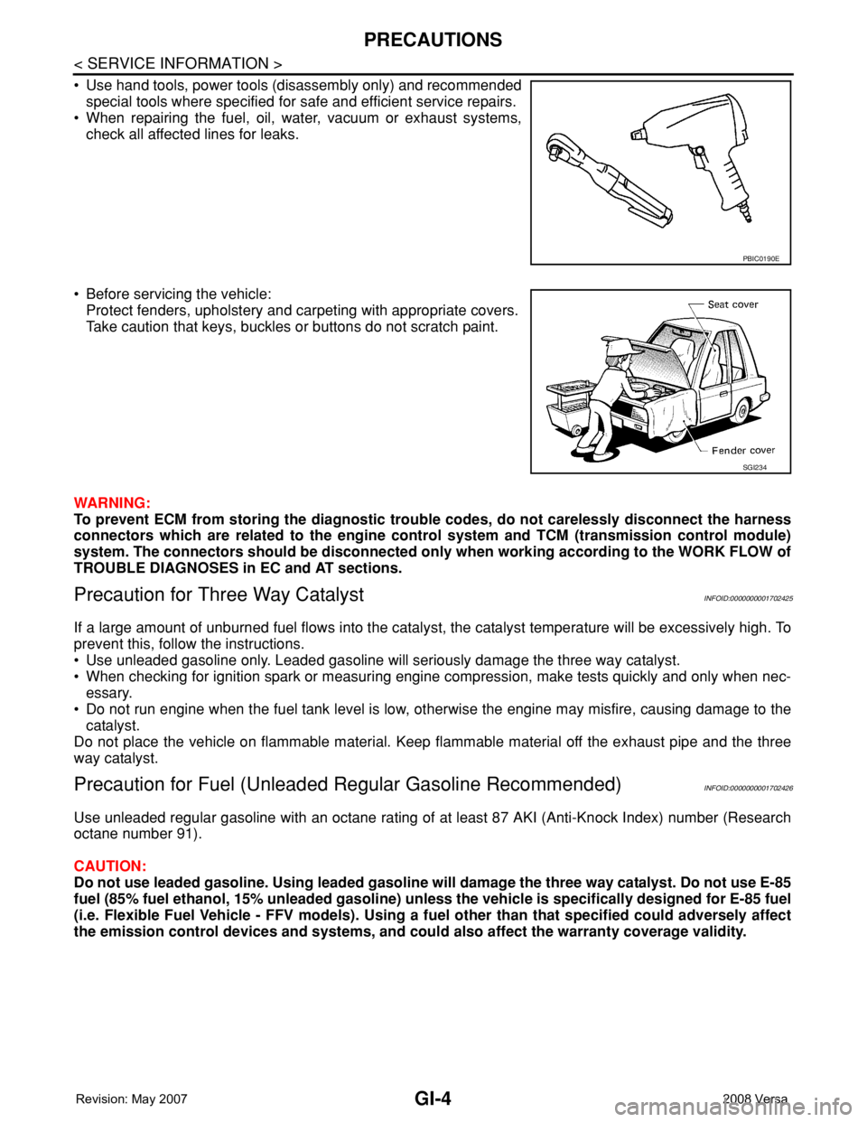
• Use hand tools, power tools (disassembly only) and recommended
special tools where specified for safe and efficient service repairs.
• When repairing the fuel, oil, water, vacuum or exhaust systems,
check all affected lines for leaks.
• Before servicing the vehicle:
Protect fenders, upholstery and carpeting with appropriate covers.
Take caution that keys, buckles or buttons do not scratch paint.
WARNING:
To prevent ECM from storing the diagnostic trouble codes, do not carelessly disconnect the harness
connectors which are related to the engine control system and TCM (transmission control module)
system. The connectors should be disconnected only when working according to the WORK FLOW of
TROUBLE DIAGNOSES in EC and AT sections.
Precaution for Three Way CatalystINFOID:0000000001702425
If a large amount of unburned fuel flows into the catalyst, the catalyst temperature will be excessively high. To
prevent this, follow the instructions.
• Use unleaded gasoline only. Leaded gasoline will seriously damage the three way catalyst.
• When checking for ignition spark or measuring engine compression, make tests quickly and only when nec-
essary.
• Do not run engine when the fuel tank level is low, otherwise the engine may misfire, causing damage to the
catalyst.
Do not place the vehicle on flammable material. Keep flammable material off the exhaust pipe and the three
way catalyst.
Precaution for Fuel (Unleaded Regular Gasoline Recommended)INFOID:0000000001702426
Use unleaded regular gasoline with an octane rating of at least 87 AKI (Anti-Knock Index) number (Research
octane number 91).
CAUTION:
Do not use leaded gasoline. Using leaded gasoline will damage the three way catalyst. Do not use E-85
fuel (85% fuel ethanol, 15% unleaded gasoline) unless the vehicle is specifically designed for E-85 fuel
(i.e. Flexible Fuel Vehicle - FFV models). Using a fuel other than that specified could adversely affect
the emission control devices and systems, and could also affect the warranty coverage validity.
PBIC0190E
SGI234
Page 1960 of 2771
REAR WINDOW DEFOGGER
GW-59
< SERVICE INFORMATION >
C
D
E
F
G
H
J
K
L
MA
B
GW
N
O
P
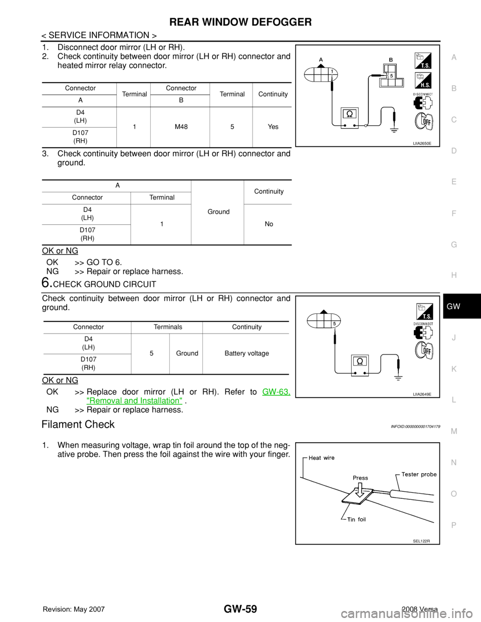
1. Disconnect door mirror (LH or RH).
2. Check continuity between door mirror (LH or RH) connector and
heated mirror relay connector.
3. Check continuity between door mirror (LH or RH) connector and
ground.
OK or NG
OK >> GO TO 6.
NG >> Repair or replace harness.
6.CHECK GROUND CIRCUIT
Check continuity between door mirror (LH or RH) connector and
ground.
OK or NG
OK >> Replace door mirror (LH or RH). Refer to GW-63,
"Removal and Installation" .
NG >> Repair or replace harness.
Filament CheckINFOID:0000000001704179
1. When measuring voltage, wrap tin foil around the top of the neg-
ative probe. Then press the foil against the wire with your finger.
Connector
Te r m i n a lConnector
Terminal Continuity
AB
D4
(LH)
1 M48 5 Yes
D107
(RH)
A
GroundContinuity
Connector Terminal
D4
(LH)
1No
D107
(RH)
LIIA2650E
Connector Terminals Continuity
D4
(LH)
5 Ground Battery voltage
D107
(RH)
LIIA2649E
SEL122R
Page 2016 of 2771
![NISSAN LATIO 2008 Service Repair Manual CAN COMMUNICATION SYSTEM
LAN-25
< FUNCTION DIAGNOSIS >[CAN]
C
D
E
F
G
H
I
J
L
MA
B
LAN
N
O
P
*1: A/T models
*2: CVT models
*3: Models for Canada
*4: Models for USA
*5: Models without ABS
NOTE:
CAN dat NISSAN LATIO 2008 Service Repair Manual CAN COMMUNICATION SYSTEM
LAN-25
< FUNCTION DIAGNOSIS >[CAN]
C
D
E
F
G
H
I
J
L
MA
B
LAN
N
O
P
*1: A/T models
*2: CVT models
*3: Models for Canada
*4: Models for USA
*5: Models without ABS
NOTE:
CAN dat](/manual-img/5/57360/w960_57360-2015.png)
CAN COMMUNICATION SYSTEM
LAN-25
< FUNCTION DIAGNOSIS >[CAN]
C
D
E
F
G
H
I
J
L
MA
B
LAN
N
O
P
*1: A/T models
*2: CVT models
*3: Models for Canada
*4: Models for USA
*5: Models without ABS
NOTE:
CAN data of the air bag diagnosis sensor unit is not used by usual service work, thus it is omitted.
Brake warning lamp signal R T
A/T check indicator signal R T
A/T self-diagnosis signal R T
OD OFF indicator signal R T
Output shaft revolution signal R T T
Shift position indicator signal R T T
Turbine revolution signal R T
CVT self-diagnosis signal R T
Input shaft revolution signal R T
OD OFF indicator signal R T
Front wiper stop position signal R T
High beam status signal RT
Low beam status signal RT
Oil pressure switch signal R T
Rear window defogger control signal RT Signal name/Connecting unit
ECM
BCM
EPS
I-KEY
M&A
ABS
TCM
*1
TCM
*2
IPDM-E
Page 2158 of 2771
HEADLAMP (FOR USA)
LT-21
< SERVICE INFORMATION >
C
D
E
F
G
H
I
J
L
MA
B
LT
N
O
P
Aiming AdjustmentINFOID:0000000001704377
PREPARATION BEFORE ADJUSTING
Before performing aiming adjustment, check the following.
1. Keep all tires inflated to correct pressures.
2. Place vehicle on level surface.
3. See that there is no-load in vehicle other than the driver (or equivalent weight placed in driver's position).
Coolant, engine oil filled up to correct level and full fuel tank, spare tire, jack and tools are properly
stowed.
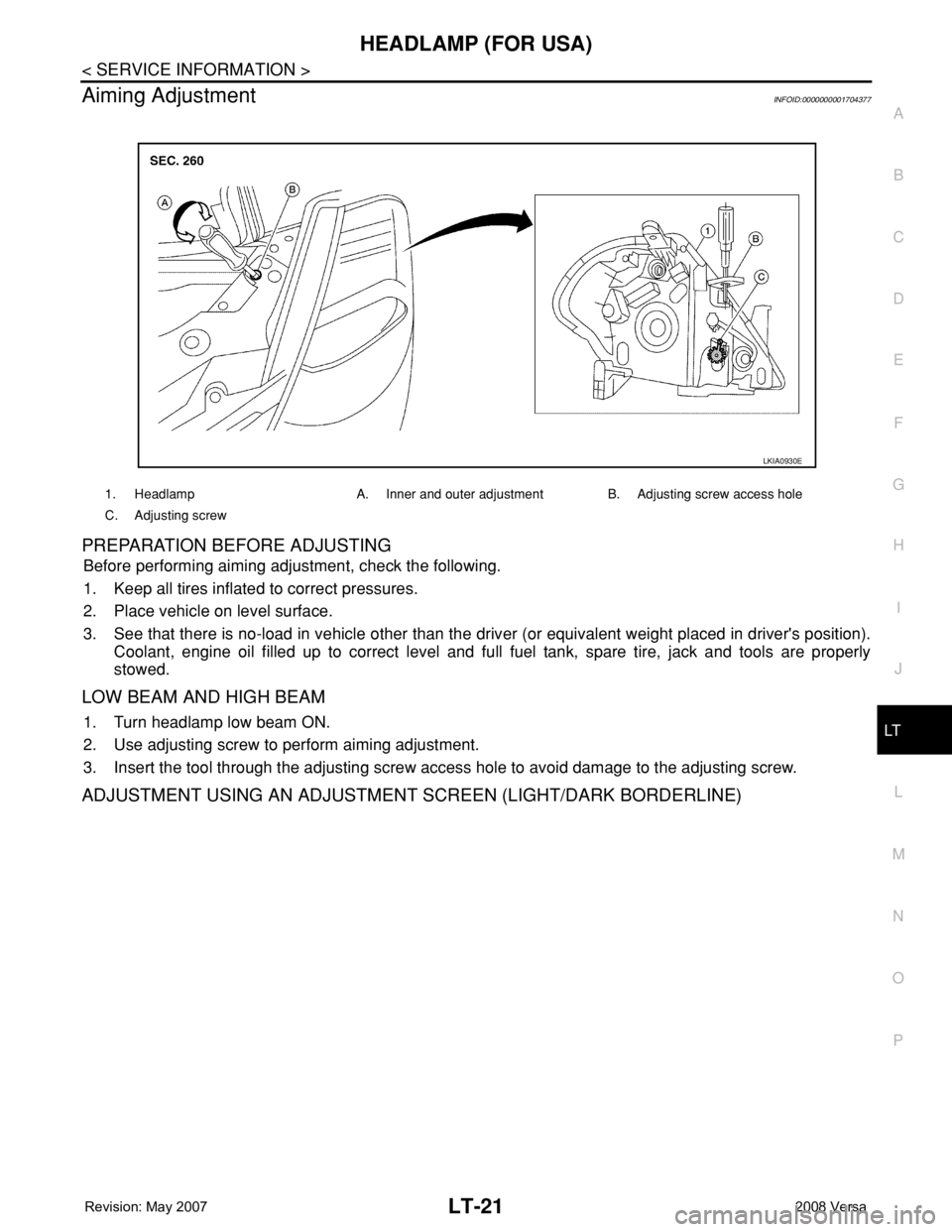
LOW BEAM AND HIGH BEAM
1. Turn headlamp low beam ON.
2. Use adjusting screw to perform aiming adjustment.
3. Insert the tool through the adjusting screw access hole to avoid damage to the adjusting screw.
ADJUSTMENT USING AN ADJUSTMENT SCREEN (LIGHT/DARK BORDERLINE)
1. Headlamp A. Inner and outer adjustment B. Adjusting screw access hole
C. Adjusting screw
LKIA0930E