2008 NISSAN LATIO wiring diagram
[x] Cancel search: wiring diagramPage 1079 of 2771

EC-5
C
D
E
F
G
H
I
J
K
L
M
ECA
N
O
P Component Description .........................................
338
CONSULT-II Reference Value in Data Monitor
Mode .....................................................................
338
On Board Diagnosis Logic ....................................338
DTC Confirmation Procedure ................................338
Wiring Diagram .....................................................340
Diagnosis Procedure .............................................341
Component Inspection ..........................................343
DTC P0448 EVAP CANISTER VENT CON-
TROL VALVE ...................................................
345
Component Description .........................................345
CONSULT-II Reference Value in Data Monitor
Mode .....................................................................
345
On Board Diagnosis Logic ....................................345
DTC Confirmation Procedure ................................345
Wiring Diagram .....................................................347
Diagnosis Procedure .............................................348
Component Inspection ..........................................349
DTC P0451 EVAP CONTROL SYSTEM
PRESSURE SENSOR ......................................
351
Component Description .........................................351
CONSULT-II Reference Value in Data Monitor
Mode .....................................................................
351
On Board Diagnosis Logic ....................................351
DTC Confirmation Procedure ................................351
Diagnosis Procedure .............................................352
Component Inspection ..........................................353
DTC P0452 EVAP CONTROL SYSTEM
PRESSURE SENSOR ......................................
355
Component Description .........................................355
CONSULT-II Reference Value in Data Monitor
Mode .....................................................................
355
On Board Diagnosis Logic ....................................355
DTC Confirmation Procedure ................................355
Wiring Diagram .....................................................357
Diagnosis Procedure .............................................358
Component Inspection ..........................................361
DTC P0453 EVAP CONTROL SYSTEM
PRESSURE SENSOR ......................................
362
Component Description .........................................362
CONSULT-II Reference Value in Data Monitor
Mode .....................................................................
362
On Board Diagnosis Logic ....................................362
DTC Confirmation Procedure ................................362
Wiring Diagram .....................................................364
Diagnosis Procedure .............................................365
Component Inspection ..........................................369
DTC P0455 EVAP CONTROL SYSTEM ..........370
On Board Diagnosis Logic ....................................370
DTC Confirmation Procedure ................................370
Diagnosis Procedure .............................................372
DTC P0456 EVAP CONTROL SYSTEM ..........377
On Board Diagnosis Logic ....................................377
DTC Confirmation Procedure ................................378
Overall Function Check .........................................378
Diagnosis Procedure .............................................379
DTC P0460 FUEL LEVEL SENSOR ...............385
Component Description .........................................385
On Board Diagnosis Logic .....................................385
DTC Confirmation Procedure ................................385
Diagnosis Procedure .............................................386
Removal and Installation .......................................386
DTC P0461 FUEL LEVEL SENSOR ...............387
Component Description .........................................387
On Board Diagnosis Logic .....................................387
Overall Function Check .........................................387
Diagnosis Procedure .............................................388
Removal and Installation .......................................388
DTC P0462, P0463 FUEL LEVEL SENSOR ..389
Component Description .........................................389
On Board Diagnosis Logic .....................................389
DTC Confirmation Procedure ................................389
Diagnosis Procedure .............................................390
Removal and Installation .......................................390
DTC P0500 VSS ..............................................391
Description .............................................................391
On Board Diagnosis Logic .....................................391
DTC Confirmation Procedure ................................391
Overall Function Check .........................................392
Diagnosis Procedure .............................................392
DTC P0506 ISC SYSTEM ...............................393
Description .............................................................393
On Board Diagnosis Logic .....................................393
DTC Confirmation Procedure ................................393
Diagnosis Procedure .............................................393
DTC P0507 ISC SYSTEM ...............................395
Description .............................................................395
On Board Diagnosis Logic .....................................395
DTC Confirmation Procedure ................................395
Diagnosis Procedure .............................................395
DTC P0605 ECM .............................................397
Component Description .........................................397
On Board Diagnosis Logic .....................................397
DTC Confirmation Procedure ................................397
Diagnosis Procedure .............................................398
DTC P0643 SENSOR POWER SUPPLY ........400
On Board Diagnosis Logic .....................................400
DTC Confirmation Procedure ................................400
Wiring Diagram ......................................................401
Diagnosis Procedure .............................................402
DTC P0850 PNP SWITCH ..............................405
Component Description .........................................405
CONSULT-II Reference Value in Data Monitor
Mode ......................................................................
405
On Board Diagnosis Logic .....................................405
DTC Confirmation Procedure ................................405
Page 1080 of 2771

EC-6
Overall Function Check .........................................406
Wiring Diagram ......................................................407
Diagnosis Procedure .............................................408
DTC P1148 CLOSED LOOP CONTROL .........411
On Board Diagnosis Logic .....................................411
DTC P1217 ENGINE OVER TEMPERATURE .412
System Description ................................................412
CONSULT-II Reference Value in Data Monitor
Mode ......................................................................
413
On Board Diagnosis Logic .....................................413
Overall Function Check .........................................413
Wiring Diagram ......................................................416
Diagnosis Procedure .............................................417
Main 13 Causes of Overheating ............................424
Component Inspection ...........................................424
DTC P1225 TP SENSOR .................................426
Component Description .........................................426
On Board Diagnosis Logic .....................................426
DTC Confirmation Procedure ................................426
Diagnosis Procedure .............................................426
Removal and Installation .......................................427
DTC P1226 TP SENSOR .................................428
Component Description .........................................428
On Board Diagnosis Logic .....................................428
DTC Confirmation Procedure ................................428
Diagnosis Procedure .............................................428
Removal and Installation .......................................429
DTC P1421 COLD START CONTROL ............430
Description .............................................................430
On Board Diagnosis Logic .....................................430
DTC Confirmation Procedure ................................430
Diagnosis Procedure .............................................430
DTC P1564 ASCD STEERING SWITCH .........432
Component Description .........................................432
CONSULT-II Reference Value in Data Monitor
Mode ......................................................................
432
On Board Diagnosis Logic .....................................432
DTC Confirmation Procedure ................................433
Wiring Diagram ......................................................434
Diagnosis Procedure .............................................435
Component Inspection ...........................................437
DTC P1572 ASCD BRAKE SWITCH ..............438
Component Description .........................................438
CONSULT-II Reference Value in Data Monitor
Mode ......................................................................
438
On Board Diagnosis Logic .....................................438
DTC Confirmation Procedure ................................439
Wiring Diagram ......................................................440
Diagnosis Procedure .............................................441
Component Inspection ...........................................445
DTC P1574 ASCD VEHICLE SPEED SEN-
SOR ..................................................................
447
Component Description .........................................447
On Board Diagnosis Logic ....................................447
DTC Confirmation Procedure ................................447
Diagnosis Procedure .............................................448
DTC P1715 INPUT SPEED SENSOR (TUR-
BINE REVOLUTION SENSOR) ........................
449
Description ............................................................449
CONSULT-II Reference Value in Data Monitor
Mode .....................................................................
449
On Board Diagnosis Logic ....................................449
Diagnosis Procedure .............................................449
DTC P1715 INPUT SPEED SENSOR (PRIMA-
RY SPEED SENSOR) .......................................
450
Description ............................................................450
CONSULT-II Reference Value in Data Monitor
Mode .....................................................................
450
On Board Diagnosis Logic ....................................450
DTC Confirmation Procedure ................................450
Diagnosis Procedure .............................................451
DTC P1805 BRAKE SWITCH ..........................452
Description ............................................................452
CONSULT-II Reference Value in Data Monitor
Mode .....................................................................
452
On Board Diagnosis Logic ....................................452
DTC Confirmation Procedure ................................452
Wiring Diagram .....................................................453
Diagnosis Procedure .............................................454
Component Inspection ..........................................455
DTC P2100, P2103 THROTTLE CONTROL
MOTOR RELAY ................................................
456
Component Description ........................................456
CONSULT-II Reference Value in Data Monitor
Mode .....................................................................
456
On Board Diagnosis Logic ....................................456
DTC Confirmation Procedure ................................456
Wiring Diagram .....................................................458
Diagnosis Procedure .............................................459
DTC P2101 ELECTRIC THROTTLE CON-
TROL FUNCTION .............................................
461
Description ............................................................461
On Board Diagnosis Logic ....................................461
DTC Confirmation Procedure ................................461
Wiring Diagram .....................................................462
Diagnosis Procedure .............................................463
Component Inspection ..........................................466
Removal and Installation .......................................466
DTC P2118 THROTTLE CONTROL MOTOR ..467
Component Description ........................................467
On Board Diagnosis Logic ....................................467
DTC Confirmation Procedure ................................467
Wiring Diagram .....................................................468
Diagnosis Procedure .............................................469
Component Inspection ..........................................470
Removal and Installation .......................................470
Page 1081 of 2771

EC-7
C
D
E
F
G
H
I
J
K
L
M
ECA
N
O
P
DTC P2119 ELECTRIC THROTTLE CON-
TROL ACTUATOR ...........................................
472
Component Description .........................................472
On Board Diagnosis Logic ....................................472
DTC Confirmation Procedure ................................472
Diagnosis Procedure .............................................473
DTC P2122, P2123 APP SENSOR ..................474
Component Description .........................................474
CONSULT-II Reference Value in Data Monitor
Mode .....................................................................
474
On Board Diagnosis Logic ....................................474
DTC Confirmation Procedure ................................474
Wiring Diagram .....................................................476
Diagnosis Procedure .............................................477
Component Inspection ..........................................479
Removal and Installation .......................................479
DTC P2127, P2128 APP SENSOR ..................480
Component Description .........................................480
CONSULT-II Reference Value in Data Monitor
Mode .....................................................................
480
On Board Diagnosis Logic ....................................480
DTC Confirmation Procedure ................................481
Wiring Diagram .....................................................482
Diagnosis Procedure .............................................483
Component Inspection ..........................................485
Removal and Installation .......................................486
DTC P2135 TP SENSOR .................................487
Component Description .........................................487
CONSULT-II Reference Value in Data Monitor
Mode .....................................................................
487
On Board Diagnosis Logic ....................................487
DTC Confirmation Procedure ................................487
Wiring Diagram .....................................................489
Diagnosis Procedure .............................................490
Component Inspection ..........................................492
Removal and Installation .......................................492
DTC P2138 APP SENSOR ...............................493
Component Description .........................................493
CONSULT-II Reference Value in Data Monitor
Mode .....................................................................
493
On Board Diagnosis Logic ....................................493
DTC Confirmation Procedure ................................494
Wiring Diagram .....................................................495
Diagnosis Procedure .............................................496
Component Inspection ..........................................499
Removal and Installation .......................................499
DTC P2A00 A/F SENSOR 1 .............................500
Component Description .........................................500
CONSULT-II Reference Value in Data Monitor
Mode .....................................................................
500
On Board Diagnosis Logic ....................................500
DTC Confirmation Procedure ................................500
Wiring Diagram .....................................................502
Diagnosis Procedure .............................................503
Removal and Installation .......................................507
ASCD BRAKE SWITCH ..................................508
Component Description .........................................508
CONSULT-II Reference Value in Data Monitor
Mode ......................................................................
508
Wiring Diagram ......................................................509
Diagnosis Procedure .............................................510
Component Inspection ...........................................514
ASCD INDICATOR ..........................................516
Component Description .........................................516
CONSULT-II Reference Value in Data Monitor
Mode ......................................................................
516
Wiring Diagram ......................................................517
Diagnosis Procedure .............................................517
ELECTRICAL LOAD SIGNAL ........................519
CONSULT-II Reference Value in Data Monitor
Mode ......................................................................
519
Diagnosis Procedure .............................................519
FUEL INJECTOR ............................................521
Component Description .........................................521
CONSULT-II Reference Value in Data Monitor
Mode ......................................................................
521
Wiring Diagram ......................................................522
Diagnosis Procedure .............................................523
Component Inspection ...........................................525
Removal and Installation .......................................525
FUEL PUMP ....................................................526
Description .............................................................526
CONSULT-II Reference Value in Data Monitor
Mode ......................................................................
526
Wiring Diagram ......................................................527
Diagnosis Procedure .............................................528
Component Inspection ...........................................530
Removal and Installation .......................................530
IGNITION SIGNAL ..........................................531
Component Description .........................................531
Wiring Diagram ......................................................532
Diagnosis Procedure .............................................535
Component Inspection ...........................................538
Removal and Installation .......................................540
REFRIGERANT PRESSURE SENSOR ..........541
Component Description .........................................541
Wiring Diagram ......................................................542
Diagnosis Procedure .............................................543
Removal and Installation .......................................545
MIL AND DATA LINK CONNECTOR .............546
Wiring Diagram ......................................................546
SERVICE DATA AND SPECIFICATIONS
(SDS) ...............................................................
548
Fuel Pressure ........................................................548
Idle Speed and Ignition Timing ..............................548
Calculated Load Value ..........................................548
Mass Air Flow Sensor ............................................548
Intake Air Temperature Sensor .............................548
Page 1211 of 2771
POWER SUPPLY AND GROUND CIRCUIT
EC-137
< SERVICE INFORMATION >
C
D
E
F
G
H
I
J
K
L
MA
EC
N
P O
POWER SUPPLY AND GROUND CIRCUIT
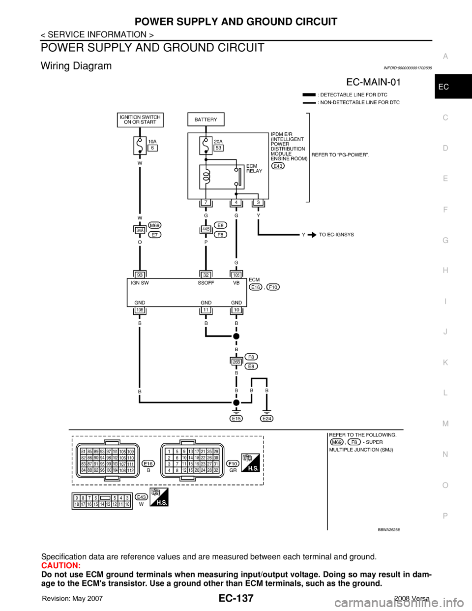
Wiring DiagramINFOID:0000000001702605
Specification data are reference values and are measured between each terminal and ground.
CAUTION:
Do not use ECM ground terminals when measuring input/output voltage. Doing so may result in dam-
age to the ECM's transistor. Use a ground other than ECM terminals, such as the ground.
BBWA2625E
Page 1213 of 2771
POWER SUPPLY AND GROUND CIRCUIT
EC-139
< SERVICE INFORMATION >
C
D
E
F
G
H
I
J
K
L
MA
EC
N
P O
OK or NG
OK >> GO TO 5.
NG >> Repair or replace ground connections.
5.CHECK ECM GROUND CIRCUIT FOR OPEN AND SHORT-I
1. Disconnect ECM harness connector.
2. Check harness continuity between ECM terminals 10, 11, 108 and ground.
Refer to Wiring Diagram.
3. Also check harness for short to power.
OK or NG
OK >> GO TO 7.
NG >> GO TO 6.
6.DETECT MALFUNCTIONING PART
Check the following.
• Harness connectors F8, E8
• Harness for open or short between ECM and ground
>> Repair open circuit or short to power in harness or connectors.
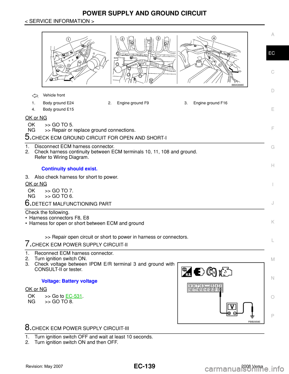
7.CHECK ECM POWER SUPPLY CIRCUIT-II
1. Reconnect ECM harness connector.
2. Turn ignition switch ON.
3. Check voltage between IPDM E/R terminal 3 and ground with
CONSULT-II or tester.
OK or NG
OK >> Go to EC-531.
NG >> GO TO 8.
8.CHECK ECM POWER SUPPLY CIRCUIT-III
1. Turn ignition switch OFF and wait at least 10 seconds.
2. Turn ignition switch ON and then OFF.
:Vehicle front
1. Body ground E24 2. Engine ground F9 3. Engine ground F16
4. Body ground E15
BBIA0698E
Continuity should exist.
Voltage: Battery voltage
PBIB2658E
Page 1214 of 2771
EC-140
< SERVICE INFORMATION >
POWER SUPPLY AND GROUND CIRCUIT
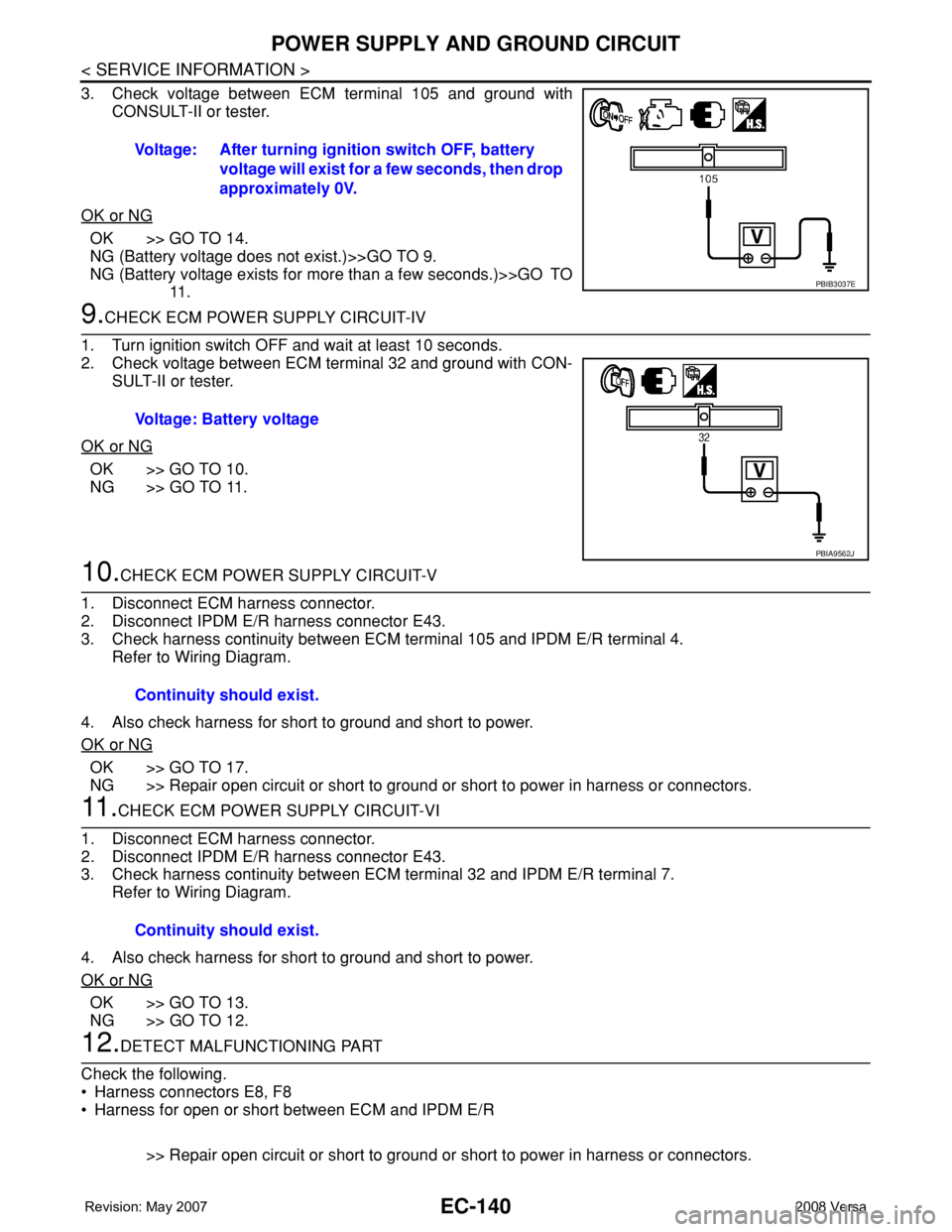
3. Check voltage between ECM terminal 105 and ground with
CONSULT-II or tester.
OK or NG
OK >> GO TO 14.
NG (Battery voltage does not exist.)>>GO TO 9.
NG (Battery voltage exists for more than a few seconds.)>>GO TO
11 .
9.CHECK ECM POWER SUPPLY CIRCUIT-IV
1. Turn ignition switch OFF and wait at least 10 seconds.
2. Check voltage between ECM terminal 32 and ground with CON-
SULT-II or tester.
OK or NG
OK >> GO TO 10.
NG >> GO TO 11.
10.CHECK ECM POWER SUPPLY CIRCUIT-V
1. Disconnect ECM harness connector.
2. Disconnect IPDM E/R harness connector E43.
3. Check harness continuity between ECM terminal 105 and IPDM E/R terminal 4.
Refer to Wiring Diagram.
4. Also check harness for short to ground and short to power.
OK or NG
OK >> GO TO 17.
NG >> Repair open circuit or short to ground or short to power in harness or connectors.
11 .CHECK ECM POWER SUPPLY CIRCUIT-VI
1. Disconnect ECM harness connector.
2. Disconnect IPDM E/R harness connector E43.
3. Check harness continuity between ECM terminal 32 and IPDM E/R terminal 7.
Refer to Wiring Diagram.
4. Also check harness for short to ground and short to power.
OK or NG
OK >> GO TO 13.
NG >> GO TO 12.
12.DETECT MALFUNCTIONING PART
Check the following.
• Harness connectors E8, F8
• Harness for open or short between ECM and IPDM E/R
>> Repair open circuit or short to ground or short to power in harness or connectors. Voltage: After turning ignition switch OFF, battery
voltage will exist for a few seconds, then drop
approximately 0V.
PBIB3037E
Voltage: Battery voltage
PBIA9562J
Continuity should exist.
Continuity should exist.
Page 1215 of 2771
POWER SUPPLY AND GROUND CIRCUIT
EC-141
< SERVICE INFORMATION >
C
D
E
F
G
H
I
J
K
L
MA
EC
N
P O
13.CHECK 20A FUSE
1. Disconnect 20A fuse from IPDM E/R.
2. Check 20A fuse.
OK or NG
OK >> GO TO 17.
NG >> Replace 20A fuse.
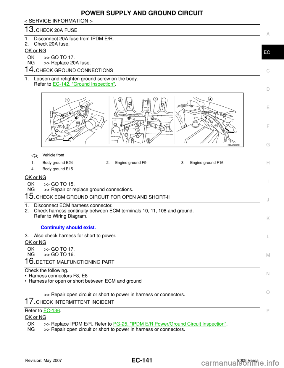
14.CHECK GROUND CONNECTIONS
1. Loosen and retighten ground screw on the body.
Refer to EC-142, "
Ground Inspection".
OK or NG
OK >> GO TO 15.
NG >> Repair or replace ground connections.
15.CHECK ECM GROUND CIRCUIT FOR OPEN AND SHORT-II
1. Disconnect ECM harness connector.
2. Check harness continuity between ECM terminals 10, 11, 108 and ground.
Refer to Wiring Diagram.
3. Also check harness for short to power.
OK or NG
OK >> GO TO 17.
NG >> GO TO 16.
16.DETECT MALFUNCTIONING PART
Check the following.
• Harness connectors F8, E8
• Harness for open or short between ECM and ground
>> Repair open circuit or short to power in harness or connectors.
17.CHECK INTERMITTENT INCIDENT
Refer to EC-136
.
OK or NG
OK >> Replace IPDM E/R. Refer to PG-25, "IPDM E/R Power/Ground Circuit Inspection".
NG >> Repair open circuit or short to power in harness or connectors.
:Vehicle front
1. Body ground E24 2. Engine ground F9 3. Engine ground F16
4. Body ground E15
BBIA0698E
Continuity should exist.
Page 1218 of 2771
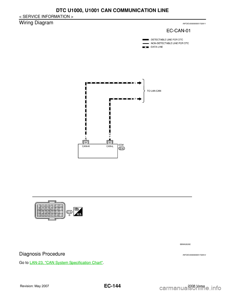
EC-144
< SERVICE INFORMATION >
DTC U1000, U1001 CAN COMMUNICATION LINE
Wiring Diagram
INFOID:0000000001702611
Diagnosis ProcedureINFOID:0000000001702612
Go to LAN-23, "CAN System Specification Chart".
BBWA2626E