Page 119 of 241

ACTUATOR
MULTIPORT FUEL SYSTEM (MFI)13A-26
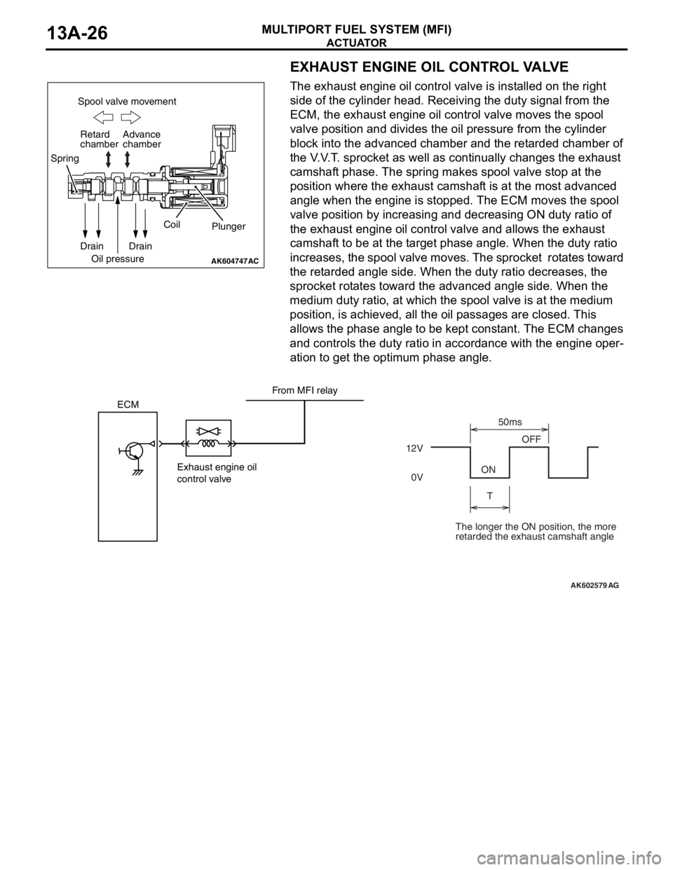
EXHAUST ENGINE OIL CONTROL VALVE
The exhaust engine oil control valve is installed on the right
side of the cylinder head. Receiving the duty signal from the
ECM, the exhaust engine oil control valve moves the spool
valve position and divides the oil pressure from the cylinder
block into the advanced chamber and the retarded chamber of
the V.V.T. sprocket as well as continually changes the exhaust
camshaft phase. The spring makes spool valve stop at the
position where the exhaust camshaft is at the most advanced
angle when the engine is stopped. The ECM moves the spool
valve position by increasing and decreasing ON duty ratio of
the exhaust engine oil control valve and allows the exhaust
camshaft to be at the target phase angle. When the duty ratio
increases, the spool valve moves. The sprocket rotates toward
the retarded angle side. When the duty ratio decreases, the
sprocket rotates toward the advanced angle side. When the
medium duty ratio, at which the spool valve is at the medium
position, is achieved, all the oil passages are closed. This
allows the phase angle to be kept constant. The ECM changes
and controls the duty ratio in accordance with the engine oper
-
ation to get the optimum phase angle.
AK604747
Spool valve movement
Retard
chamber
Spring
Drain
Oil pressureCoil
Plunger
Drain Advance
chamber
AC
AK602579
ECM
Exhaust engine oil
control valve12VOFF
ON
T50ms
0V
AG
From MFI relay
The longer the ON position, the more
retarded the exhaust camshaft angle
Page 120 of 241

ACTUATOR
MULTIPORT FUEL SYSTEM (MFI)13A-27
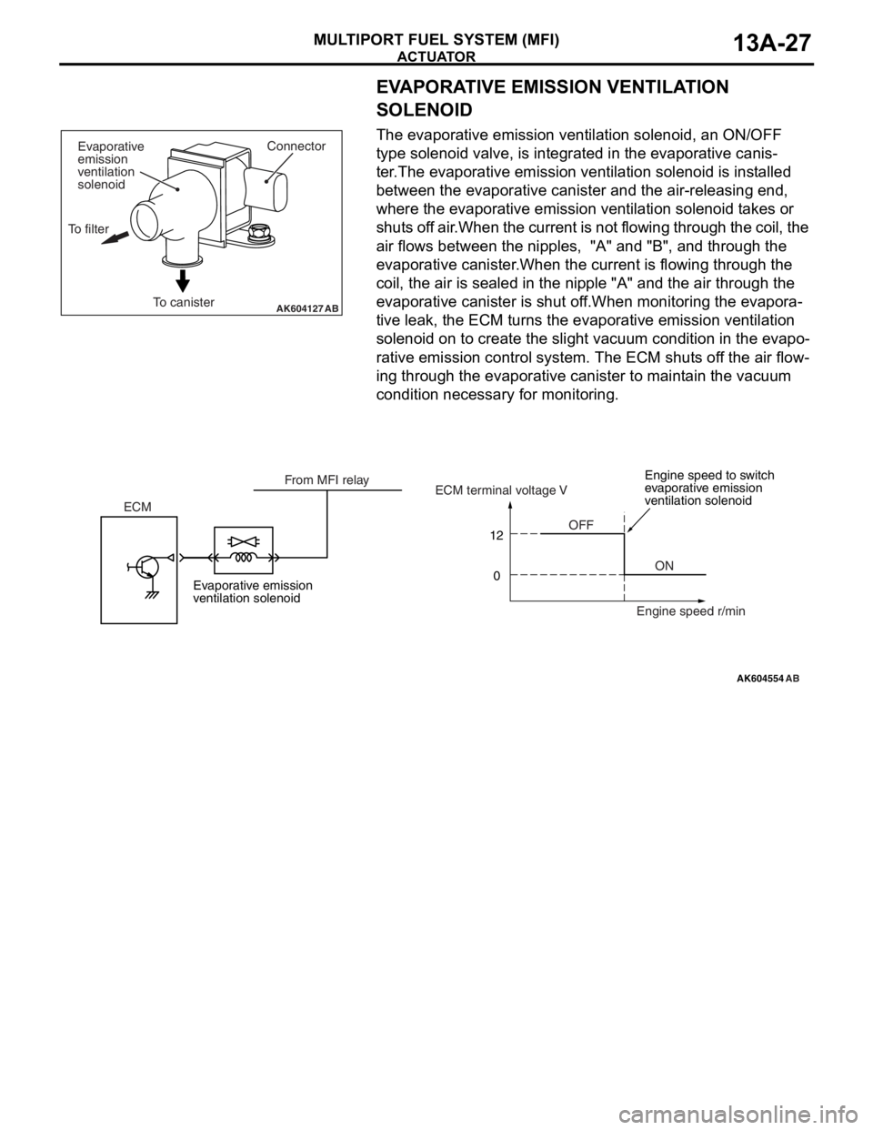
EVAPORATIVE EMISSION VENTILATION
SOLENOID
The evaporative emission ventilation solenoid, an ON/OFF
type solenoid valve, is integrated in the evaporative canis
-
ter.The evaporative emission ventilation solenoid is installed
between the evaporative canister and the air-releasing end,
where the evaporative emission ventilation solenoid takes or
shuts off air.When the current is not flowing through the coil, the
air flows between the nipples, "A" and "B", and through the
evaporative canister.When the current is flowing through the
coil, the air is sealed in the nipple "A" and the air through the
evaporative canister is shut off.When monitoring the evapora
-
tive leak, the ECM turns the evaporative emission ventilation
solenoid on to create the slight vacuum condition in the evapo
-
rative emission control system. The ECM shuts off the air flow-
ing through the evaporative canister to maintain the vacuum
condition necessary for monitoring.
AK604127ABTo canisterConnector
Evaporative
emission
ventilation
solenoid
To filter
AK604554
12
0
AB
OFF
ON ECMECM terminal voltage V
Engine speed r/min From MFI relay
Evaporative emission
ventilation solenoidEngine speed to switch
evaporative emission
ventilation solenoid
Page 121 of 241
ACTUATOR
MULTIPORT FUEL SYSTEM (MFI)13A-28
GENERATOR G TERMINAL
ECM uses ON/OFF of generator G terminal to control genera-
tor output voltage. When the power transistor in the ECM turns
ON, output voltage gets adjusted to about 12.8 V. When gener
-
ator output voltage drops to 12.8 V it becomes lower than volt-
age of the charged battery and almost no current is output from
the generator. When the power transistor in the ECM turns
OFF, output voltage gets adjusted to about 14.7 V. When gen
-
erator output voltage is about 14.7 V, generator outputs current
to produce electricity. In case electric load is generated sud
-
denly, ECM controls generator G terminal's On-duty to limit the
sudden increase in generator load due to generation and thus
prevents change in idle speed.
AK602233AD
Field coil
IC regulator
GeneratorG Ignition switch-IG
Battery
BS
ECM
Page 128 of 241
IGNITION TIMING AND CONTROL FOR CURRENT CARRYING TIME
MULTIPORT FUEL SYSTEM (MFI)13A-35
IGNITION TIMING AND CONTROL FOR CURRENT
CARRYING TIME
M2132027100089
Ignition timing is pre-set according to engine driving
conditions. Compensations are made according to
pre-set values depending on conditions such as
engine coolant temperature, battery voltage etc. to
decide optimum ignition timing. Primary current con
-
nect/disconnect signal is sent to the power transistor
to control ignition timing. Ignition is done in sequence
of cylinders 1, 3, 4, 2.
System Configuration Diagram
AK502722AD
ECM MFI relay
Spark plugs Ignition
coils
Cylinder No. 1 2 3 4Battery
Mass airflow sensor
Intake air temperature sensor
Manifold absolute
pressure sensor
Engine coolant
temperature sensor
Intake camshaft position sensor
Exhaust camshaft position sensor
Crankshaft position sensor
Knock sensor
Ignition switch-ST Throttle position sensor
Page 129 of 241
IGNITION TIMING AND CONTROL FOR CURRENT CARRYING TIME
MULTIPORT FUEL SYSTEM (MFI)13A-36
1. Ignition distribution control
Based on the crankshaft position sensor signal and camshaft
position sensor signal, ECM decides the ignition cylinder, cal
-
culates the ignition timing and sends the ignition coil primary
current connect/disconnect signal to the power transistor of
each cylinder in the ignition sequence.
AK604624
Exhaust
AB
Cylinder stroke
No. 1 Cylinder
No. 3 Cylinder
No. 4 Cylinder
No. 2 CylinderCombustion
Intake
Exhaust
Combustion CompressionIgnition
Intake
Exhaust CompressionCombustion
Intake CompressionIntake
Exhaust
Combustion
Compression H
L
H
L
H
L Crankshaft
position
sensor signal
Intake camshaft
position sensor
signal
Exhaust camshaft
position sensor
signal
Page 132 of 241

THROTTLE VALVE OPENING ANGLE CONTROL AND IDLE SPEED CONTROL
MULTIPORT FUEL SYSTEM (MFI)13A-39
List of main compensations for throttle valve opening angle and idle speed control
Initialize control
After ignition switch turns OFF, ECM drives the throt-
tle valve from fully closed position to fully open posi-
tion and records the fully closed/open studied value
of the throttle position sensor (main and sub) output
signals. The recorded studied values are used as
studied value compensation for compensating basic
target opening angle when the engine is started next.
CompensationsContent
Stable idle compensation (immediately after start)In order to stabilize idle speed immediately after
start, target opening angle is kept big and then
gradually reduced. Compensation values are set
based on the engine coolant temperature.
Rotation speed feedback compensation (while
idling)In case there is a difference between the target idle
speed and actual engine speed, ECM
compensates the throttle valve opening angle
based on that difference.
Atmospheric pressure compensationAt high altitudes atmospheric pressure is less and
the intake air density is low. So, the target opening
angle is compensated based on atmospheric
pressure.
Engine coolant temperature compensationCompensation is made according to the engine
coolant temperature. The lower the engine coolant
temperature the greater the throttle valve opening
angle.
Electric load compensationThrottle valve opening angle is compensated
according to electric load. The greater the electric
load, the greater the throttle valve opening angle.
Compensation when shift is in D range When transmission is changed from P or N range
to some other range, throttle valve opening angle is
increased to prevent reduction in engine speed.
Compensation when A/C is functioningThrottle valve opening angle is compensated
according to functioning of A/C compressor. While
A/C compressor is being driven, the throttle valve
opening angle is increased.
Power steering fluid pressure compensationThrottle valve opening angle is compensated
according to power steering functioning. When
power steering oil pressure rises and power
steering pressure switch is ON, the throttle valve
opening angle is increased.
Page 133 of 241

MIVEC (Mitsubishi Innovative Valve Timing Electronic Control System)
MULTIPORT FUEL SYSTEM (MFI)13A-40
MIVEC (Mitsubishi Innovative Valve Timing Electronic
Control System)
M2132023500212
MIVEC is the system which continuously varies and
controls the opening and closing timings of the intake
valve and the exhaust valve.
System Configuration Diagram
MIVEC allows the optimum valve timing to be con-
trolled in accordance with the engine operation and
the idling stability to be improved, as well as the out
-
put and the torque to be better in all the operation
ranges.
•The ECM assesses the engine operation through
the signals from each sensor.
•Based on the assessed information, the ECM
sends the duty signal to the intake engine oil con
-
trol valve and exhaust engine oil control valve as
well as controls the spool valve position.
•Changing the spool valve position allows the oil
pressure to be divided into the retarded chamber
and the advanced chamber, as well as allows the
phases of the intake camshaft and the exhaust
camshaft to be continuously changed.
AK604826AB
Crankshaft
position sensor
Manifold absolute
pressure sensor
Intake camshaft
position sensorECMSpool valve
To oil pan
To oil pan Oil pressureAdvance direction Spool valve movementRetard direction Intake engine oil control valve
Retard chamber
Advance chamber
Spring
Crankshaft
position sensor
Manifold absolute
pressure sensor
Exhaust camshaft
position sensorECMSpool valve
To oil pan
To oil pan Oil pressureRetard direction Spool valve movementAdvance direction Exhaust engine oil control valve
Advance chamber
Retard chamber
Spring
Page 138 of 241
MULTIPORT FUEL INJECTION (MFI) RELAY CONTROL
MULTIPORT FUEL SYSTEM (MFI)13A-45
MULTIPORT FUEL INJECTION (MFI) RELAY CONTROLM2132006000173
When the ignition switch-IG "ON" signal is input,
ECM turns ON the power transistor for control of the
MFI relay. As a result, current flows through the MFI
relay's coil, the relay switch turns ON and power is
supplied to each sensor and actuator. Also, when
ignition switch-IG "OFF" signal is input, ECM per
-
forms the following controls and then turns OFF the
power transistor for control of MFI relay.
•Throttle valve initializing control
AK604134AB OFF
ON
IG2 STLOCK
ACC
IG1
MFI relay
Power
supply
MFI relay control Ignition switch-IGBattery
back up To each sensor and
actuatorIgnition switch
ETACS-ECU Battery
ECM