2008 MINI COOPER CONVERTIBLE ignition
[x] Cancel search: ignitionPage 67 of 176

65
OVERVIEW REPAIRS OPERATIONCONTROLS DATA INDEX
WASHER FLUID CRUISE CONTROL
*
Always observe the instructions on the con-
tainers.<
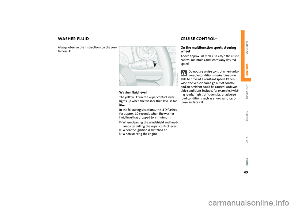
Washer fluid levelThe yellow LED in the wiper control lever
lights up when the washer fluid level is too
low.
In the following situations, the LED flashes
for approx. 10 seconds when the washer
fluid level has dropped to a minimum:
>When cleaning the windshield and head-
lamps by pulling the wiper control lever
>When the ignition is switched on
>When starting the engine
On the multifunction sports steering
wheelAbove approx. 20 mph / 30 km/h the cruise
control maintains and stores any desired
speed.
Do not use cruise control when unfa-
vorable conditions make it inadvis-
able to drive at a constant speed. Other-
wise, the vehicle could go out of control
and an accident could be caused. Unfavor-
able conditions include, for example, twist-
ing roads, high traffic density, or adverse
road conditions such as snow, rain, ice, or
loose surfaces.<
Page 68 of 176

66
CRUISE CONTROL
*
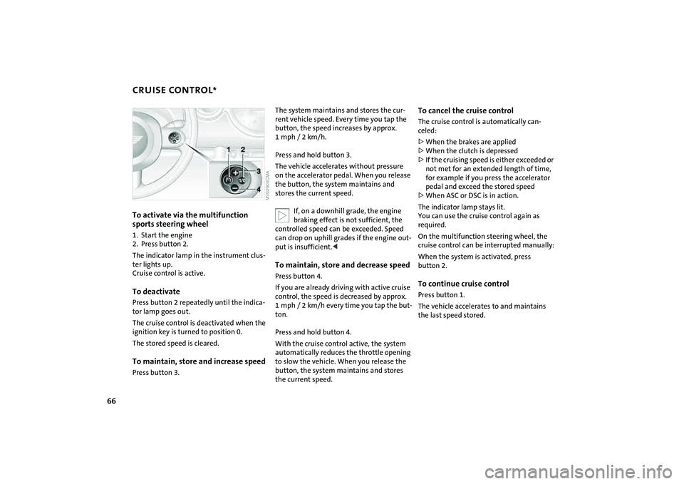
To activate via the multifunction
sports steering wheel
1. Start the engine
2. Press button 2.
The indicator lamp in the instrument clus-
ter lights up.
Cruise control is active.To deactivatePress button 2 repeatedly until the indica-
tor lamp goes out.
The cruise control is deactivated when the
ignition key is turned to position 0.
The stored speed is cleared.To maintain, store and increase speedPress button 3.
The system maintains and stores the cur-
rent vehicle speed. Every time you tap the
button, the speed increases by approx.
1mph/ 2km/h.
Press and hold button 3.
The vehicle accelerates without pressure
on the accelerator pedal. When you release
the button, the system maintains and
stores the current speed.
If, on a downhill grade, the engine
braking effect is not sufficient, the
controlled speed can be exceeded. Speed
can drop on uphill grades if the engine out-
put is insufficient.
control, the speed is decreased by approx.
1 mph / 2 km/h every time you tap the but-
ton.
Press and hold button 4.
With the cruise control active, the system
automatically reduces the throttle opening
to slow the vehicle. When you release the
button, the system maintains and stores
the current speed.
To cancel the cruise controlThe cruise control is automatically can-
celed:
>When the brakes are applied
>When the clutch is depressed
>If the cruising speed is either exceeded or
not met for an extended length of time,
for example if you press the accelerator
pedal and exceed the stored speed
>When ASC or DSC is in action.
The indicator lamp stays lit.
You can use the cruise control again as
required.
On the multifunction steering wheel, the
cruise control can be interrupted manually:
When the system is activated, press
button 2.To continue cruise controlPress button 1.
The vehicle accelerates to and maintains
the last speed stored.
Page 69 of 176

67
OVERVIEW REPAIRS OPERATIONCONTROLS DATA INDEX
ODOMETER CLOCK FUEL GAUGE 1 Trip odometer/clock
2OdometerTrip odometer/clockTo switch between the trip odometer and
the clock:
Press the button.
To reset the trip odometer to zero:
Press the button until the trip odometer
shows zero.
To set the clock, refer to the information
below.OdometerWhen the ignition key is not in the ignition
lock, you can activate the displays shown in
the illustration by pressing the button in
the display elements.
Setting The clock must be shown on the display.
1. If necessary, press button 1 to display
the clock
2. Press button 1 for approx. 5 seconds to
activate the clock-setting mode
3. Press button 1 to select 12-hour or
24-hour mode
4. Wait approx. 5 seconds until the hours
display is shown
5. Press button 1 to set the hour
6. Wait approx. 5 seconds until the min-
utes display is shown
7. Press button 1 to set the minute.
The time entered is stored automatically
after approx. 1 minute.
In the speedometer or Cockpit Chrono
Pack*If the LED begins to be lit continuously,
there are approx. 2.1 gallons/8 liters of fuel
left in the tank.
Fuel tank capacity:
Approx. 13.2 gallons/50 liters.
When you switch on the ignition, the LED
lights up briefly to confirm that the system
is operational.
If the angle of the vehicle varies, for exam-
ple when you are driving in mountainous
areas, the needle may fluctuate slightly.
Refill the gas tank early. If you drive
to the last drop of fuel, engine func-
tions are not guaranteed and damage can
occur.<
Page 70 of 176

68
FUEL GAUGE COOLANT TEMPERATURE GAUGE In the navigation system*
Please also comply with the instruc-
tions in the previous section.<
If the LED changes from orange to red,
there are approx. 2.1 gallons/8 liters of fuel
left in the tank.
Coolant temperature gaugeDepending on the equipment version, a
coolant temperature gauge is located in
the speedometer or the Cockpit Chrono
Pack.
Low temperature:
The engine is still cold. Drive at moderate
engine and vehicle speeds.
Center position:
Normal operating temperature of the
engine.
High temperature:
As soon as there is a deviation from the
center position upwards or to the left:
Drive with moderation and at low engine
speeds. If necessary, switch off the engine
and allow it to cool down.
Checking coolant level, refer to page122.Temperature warning LED 1 comes on while the vehicle is in
motion: engine is too hot. Switch off the
engine immediately and allow it to cool
down.
When you switch on the ignition, the LED 1
lights up briefly to confirm that the system
is operational.Equipment with navigation system* or
Cockpit Chrono Pack*
Coolant temperature warning
lamp 2 comes on while the vehicle
is in motion: engine is too hot.
Switch off the engine immediately and
allow it to cool down.
Page 71 of 176

69
OVERVIEW REPAIRS OPERATIONCONTROLS DATA INDEX
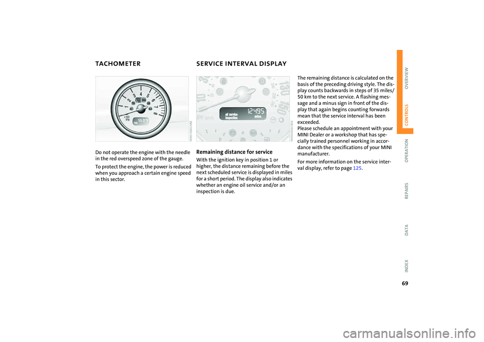
TACHOMETER SERVICE INTERVAL DISPLAYDo not operate the engine with the needle
in the red overspeed zone of the gauge.
To protect the engine, the power is reduced
when you approach a certain engine speed
in this sector.
Remaining distance for serviceWith the ignition key in position 1 or
higher, the distance remaining before the
next scheduled service is displayed in miles
for a short period. The display also indicates
whether an engine oil service and/or an
inspection is due.
The remaining distance is calculated on the
basis of the preceding driving style. The dis-
play counts backwards in steps of 35 miles/
50 km to the next service. A flashing mes-
sage and a minus sign in front of the dis-
play that again begins counting forwards
mean that the service interval has been
exceeded.
Please schedule an appointment with your
MINI Dealer or a workshop that has spe-
cially trained personnel working in accor-
dance with the specifications of your MINI
manufacturer.
For more information on the service inter-
val display, refer to page125.
Page 75 of 176

73
OVERVIEW REPAIRS OPERATIONCONTROLS DATA INDEX
DRIVING STABILITY CONTROL SYSTEMSSwitching off the ASC or DSCBriefly press the switch.
The indicator lamp stays lit.
When driving with snow chains or to 'rock
free' in snow, it can be helpful to switch off
the ASC/DSC for a brief period.
To maintain vehicle stability, always
drive with the ASC or DSC switched
on whenever possible.<
Switching the ASC or DSC on againBriefly press the switch once again.
The indicator lamp goes out.Indicator lamp
The indicator lamp will go out
shortly after the ignition has been
switched on, refer to pages17, 18.
The indicator lamp flashes:
ASC or DSC is regulating drive torque and
braking forces.
The indicator lamp lights up continuously:
the system is malfunctioning or has been
switched off at the button. Have the sys-
tem checked as soon as possible.
Page 82 of 176

80
AIRBAGStivated or activated, refer to Functional sta-
tus of the front passenger airbags below. <
Before transporting a child on the
front passenger seat, read the safety
notes and instructions under Transporting
children safely, refer to page50.
Adolescents and adults sitting in certain
positions could also deactivate the front
and side airbags for the front passenger;
the indicator lamp for the front passenger
airbags comes on. In such cases, the occu-
pant should change his or her sitting posi-
tion so that the front passenger airbags are
activated and the indicator lamp goes out.
If the airbags are not activated although
the seat occupant has changed his or her
position, have the occupant sit on a rear
seat. Do not attach covers, cushions, ball
mats or other items to the front passenger
seat unless they are specifically recom-
mended by the manufacturer of your MINI.
Do not place any objects under the seat
which could press against the seat from
below. Otherwise, a correct analysis of the
seat cushion is not ensured.<
Functional status of the front
passenger airbagsAs an example, the illustration shows the
indicator lamp for front passenger airbags
in the MINI Convertible.
In accordance with whether and how the
front passenger seat is occupied, the indi-
cator lamp for the front passenger airbags
shows the functional status of the front
and side airbags for the front passenger.
The indicator lamp shows whether the
front passenger airbags are activated or
deactivated.
>The indicator lamp comes on as intended
when a child in a specially designated
child-restraint system is detected on the
front passenger's seat.
The front and side airbags for the front
passenger are not activated.
>The indicator lamp does not come on
when the system detects a person of suf-
ficient size sitting correctly on the seat,
for example. The front and side airbags
for the front passenger are activated.
>The indicator lamp does not come on
when the seat is empty. However, the
front and side airbags for the front pas-
senger are not activated. Operational readiness of the airbag
system
Starting from ignition key
position 1, the warning lamp in the
display elements lights up briefly
for confirmation that the entire airbag sys-
tem and the seat belt tensioners are opera-
tional.
Airbag system malfunctioning>The warning lamp does not come on
along with ignition key position 1
>The warning lamp stays lit continuously.
In the event of a malfunction, have
the airbag system checked immedi-
ately. Otherwise, there is a risk that the sys-
tem will not function as intended in an
accident of sufficient severity.<
Page 83 of 176

81
OVERVIEW REPAIRS OPERATIONCONTROLS DATA INDEX
PARK DISTANCE CONTROL (PDC)
*
The concept
The PDC assists you when you back into a
parking space. A signal tone tells you the
current distance to an object behind your
vehicle. To do this, four ultrasonic sensors
in the rear bumper measure the distance to
the nearest object.
The sensors on each side have a range of
approx. 2 ft/60 cm, the middle sensors one
of approx. 5 ft/1.5 m.
PDC is a parking aid that can identify
objects if they are approached slowly,
as is generally the case when parking.
Avoid driving towards objects rapidly; due
to underlying physical principles, the sys-
tem may otherwise alert you too late for
you to take evasive steps.
one second after you select reverse gear or
place the selector lever in position R.
Wait for this one second before you
drive backwards.<
The system is deactivated when you shift
away from Reverse.
You can have a signal tone set as a
confirmation that PDC has been acti-
vated.<
Acoustical signalsThe distance to an object is indicated by a
tone sounding at intervals. As the distance
between vehicle and object decreases, the
intervals between the tones become
shorter. A continuous tone indicates the
presence of an object less than 12 in/30 cm
away.
The warning signal is canceled after
approx. three seconds if the distance to the
object remains constant during this time,
for instance if you are moving parallel to a
wall.MalfunctionA continuous high-pitched tone will sound
during initial activation. The system is mal-
functioning. Have the system checked.Volume controlThe volume of the Park Distance Control
signal can be adjusted from level 1, soft, to
level 6, loud.
You can have this function set.<
System limitations
Even with PDC, final responsibility for
estimating the distance between the
vehicle and any objects always remains
with the driver.
Even when sensors are involved, there is a
blind spot in which objects cannot be
detected. Recognition of some objects can
be beyond the limits of physical ultrasonic
measurement, for example with towing
bars or hitches or with thin or wedge-
shaped objects. It is also possible that low
objects already detected, such as a curb
edge, can disappear in the blind spot of the
sensors before a continuous tone is
sounded, or that protruding objects higher
above the ground, such as ledges, are not
detected.
Loud sources of sound outside and inside
your vehicle can drown the PDC signal
tone.<
Keep the sensors clean and free of ice
or snow in order to ensure that they
will continue to operate effectively.
Do not apply high pressure spray to the
sensors for a prolonged period of time.
Always maintain a distance which is
greater than 4 in/10 cm.<