2008 MERCEDES-BENZ SL ROADSTER towing
[x] Cancel search: towingPage 16 of 317
13
Vehicle weights
............... 299
Wheels .................. 293, 295
Telephone
see Mobile phone
Temperature
Coolant ..................... 106
Engine oil (on-board computer) ...111
Outside temperature ...........106
Third brake lamp
Display message .............. 222
Tightening torque ............... 274
Time Lap time (on-board computer) ....112
Timer (on-board computer) .......112
TIREFIT kit Using ....................... 266
Total distanc erecorder ....... 26, 108
Resetting the trip meter .........106
Tow-away protection ..............60
Towing ........................ 282
Towing eye Fitting ....................... 281
Removing .................... 282
Traction control .................. 55
Transmission output (maximum) Telephone/two-wa yradio ....... 287
Transport (vehicle) ..............282
Trip computer Menu (on-board computer) ......122Trip meter
...................... 110
Resetting .................... 106
Turn signal lamps
Display message .............. 221
TV
Operation (on-board computer) ...114
Two-way radio
Installatio n................... 287
Tyre grip ....................... 192
Tyre pressure ................... 184
Calling up (on-board computer) ..186
Display message ..209, 210, 211, 225
Table (see Fuel filler flap) ........175
see Tyr epressure
Tyre pressure los swarning system 185
Tyre pressure monitor Warning lamp ................. 238
Tyres
Direction of rotatio n............ 183
General notes ................. 182
Technical data ............ 293, 295
Tyre tread ...................... 184 U
Unladen weight ................. 299
Unlocking Emergency unlocking ...........255
From the insid e(central unlocking
button) ....................... 68Up (display message)
............111 V
Variable Speedtronic .............134
Vario-roof see Roof
Vehicle
Emergency unlocking .......255, 256
Individua lsettings (on-board com-
puter) ....................... 116
Leaving parked up .............254
Towing ...................... 282
Transporting .................. 282
Vehicle battery ................. 276
Vehicle dimensions ..............298
Vehicle electronics ..............287
Vehicle identification number
(VIN) ...................... 288, 289
Vehicle identification plates ......288
Vehicle level .................... 139
Adjusting .................... 140
Vehicle tool kit .................. 200
Vehicle weights ................. 299 W
Warning and indicator lamp ABS/ESP ®
................... 234
ABS (yellow) .................. 233
ESP ®
OFF .................... 234 Index
230_AKB; 5; 4, en-GB
bjanott,
Version: 2.9.6
2008-04-08T15:09:54+02:00
-Seite 13 Dateiname: 6515_3089_02_buchblock.pdf; preflight
Page 60 of 317
Driving safet
ysystems 57
If yo
udeact ivate ESP ®
:
R ESP ®
no longe rimp roves driving stability.
R engine torque is no longe rlimit ed and the
drive wheels ar eabletos pin. Th espinning
wheels produce acutting effect for better
traction.
R tractio ncontrol is still activated.
R ESP ®
still provide ssuppo rt when yo ubrake
firmly.
i If ESP ®
is deactivate dand one or more
wheels start to spin, the vwarning lamp
in the instrumen tcluste rdoesn ot flash. In
such situations ESP ®
will not stabilise the
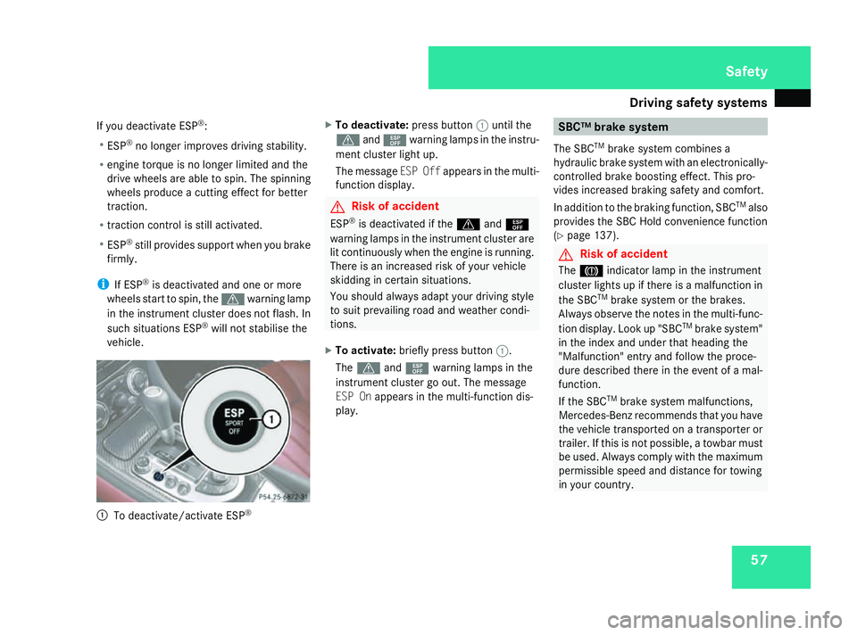
vehicle. 1
To deactivate/activat eESP® X
To deactivate: pressbutton 1untilt he
v and¯ warning lamp sinthe instr u-
ment cl usterlight up.
Th em essage ESPO ffappear sinthe multi-
function displa y. G
Risk of ac
cident
ESP ®
is deactivated if the vand¯
warning lamp sinthe instr umentclus tera re
li tc ontin uously when the engin eisrunning.
Ther eisani ncreased risk of yourvehicle
skiddin gincertain situations.
Yo us hould alwaysadap tyou rd riving style
to suit prevailing road an dweather condi-
tions.
X To activate: brieflypress button 1.
The v and¯ warning lamp sinthe
instr ument clus tergoo ut.T he message
ES POn appear sinthe multi-function dis-
play. SBC
™brake system
Th eS BCTM
brak esystemc ombines a
hydrauli cbrake syste mwithane lectronicall y-
controlled brak eboost inge ffec t. This pro-
vide sincreased brakin gsafet yand comfort.
In additio ntothe brakin gfun ction, SBC TM
also
provides the SBC Hold convenienc efunction
(Y page 137). G
Risk of ac
cident
The 3 indicator lamp in the instr ument
cl us terlight supift here isamalfun ction in
the SBC TM
brak esystemort he brakes.
Alwa ysobserve the note sinthe multi-func-
tio nd isplay. Lookup"SBC TM
brak esystem"
in the inde xand un dertha th eading the
"Malfunction" entry an dfollow the proce-
dure described there in the event of amal-
function.
If the SBC TM
brak esystemm alfun ctions,
Mercedes-Benz recommends tha tyou have
the vehicl etransported on atransporter or
trailer .Ifthisisn ot possible ,atowba rmust
be used. Alwayscompl ywitht he maxim um
permissible spee dand distance fo rtowing
in your country. Safety
230_AKB; 5; 4, en-GB
bjanott,
Version: 2.9.6
2008-04-08T15:09:54+02:00
-Seite 57 ZDateiname: 6515_3089_02_buchblock.pdf; preflight
Page 66 of 317
63
Opening and closing
...........................64
Key positions ....................................... 73
Seats .................................................... 74
Steering wheel .................................... 78
Mirrors ................................................. 80
Memor yfunctions ............................... 82
Seat belts ............................................. 83
Lights ................................................... 87
Windscreen wipers .............................92
Side windows ...................................... 93Driving and parking
............................95
Automatic transmission .....................98
Instrument cluster ............................105
On-boar dcomputer .......................... 106
Driving systems ................................ 124
Air conditioning ................................. 144
Opening/closing the roof .................154
Loading and stowing ........................159
Features ............................................. 165 Controls
230_AKB
;5;4,en-GB
bjanott, Version:2.9.6
2008-04-08T15:09:54+02:0
0-Seite 63 Dateiname: 6515_3089_02_buchblock.pdf; preflight
Page 140 of 317
Driving sys
tems 137
Permanent Speedtroni
cisd eact ivated.
R Al imit spee dbetween 240 km/h and
160 km/h in increments of 10 km/h
X To select adifferen tdisplay ,press the
j, èorÿ button. SBC Hold
SBC ®
Hol dassis ts the driver in the following
situations:
R when pulling away ,especially on steep
slopes
R when manoeuvring on steep slopes
R when waiting in traffic
Th ev ehicl eisk epts tationar ywithout the
driver having to depress the brake pedal.
Th eb raking effect is cancelle dand SBC Hold
deactivate dwheny ou depress the accelera-
tor peda ltopulla way.
Activation conditions Yo
uc an activate SBC Hol dif:
R the vehicl eisstationary
R the engine is running
R the driver's door is closed R
the parking brake is not applied
R the bonnet is closed
R the selector lever is in position D,Ror N
Activating SBC Hold X
Make sure tha tthe activation conditions
ar em et.
X Depres sthe brake.
X Depres sthe brake agai nquickl yu ntil
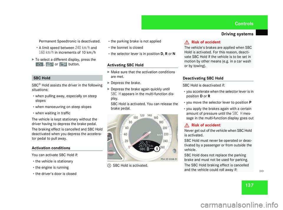
SBC H appear sinthe multi-functio ndis-
play.
SBC Hol disactivated. Yo ucan release the
brake pedal. 1
SBC Hol disactivated. G
Ris
kofa ccident
Th ev ehicle' sbrakes ar eapplied when SBC
Hol disa ctivated. For thi sreason, deacti-
vate SBC Hol difthe vehicl eistobes etin
motion by other means (e.g. in acarwash
or by towing).
Deactivating SBC Hold SBC Hol
disdeactivate dif:
R yo ua ccelerate when the selector lever is in
position Dor R
R yo um ovet he selector lever to position P
R yo ua pply the brakes agai nwithac ertain
amount of pressure unti lthe SBC H mes-
sage in the multi-functio ndisplay goes out G
Ris
kofa ccident
Never ge toutof the vehicl ewhenS BC Hold
is activated.
SBC Hol dmustn eve rbeo perated or deac-
tivate dbyapassenge rorfromo utside the
vehicle.
SBC Hol ddoesn ot replace the parking
brake and must not be used for parking.
Th eS BC Hol dbraking effect is cancelled
and the vehicl ecould rol lawa yif: Controls
230_AKB; 5; 4, en-GB
bjanott,
Version: 2.9.6 2008-04-08T15:09:54+02:00-Seite 137 ZDateiname: 6515_3089_02_buchblock.pdf; preflight
Page 162 of 317
Loading and stowing
1591
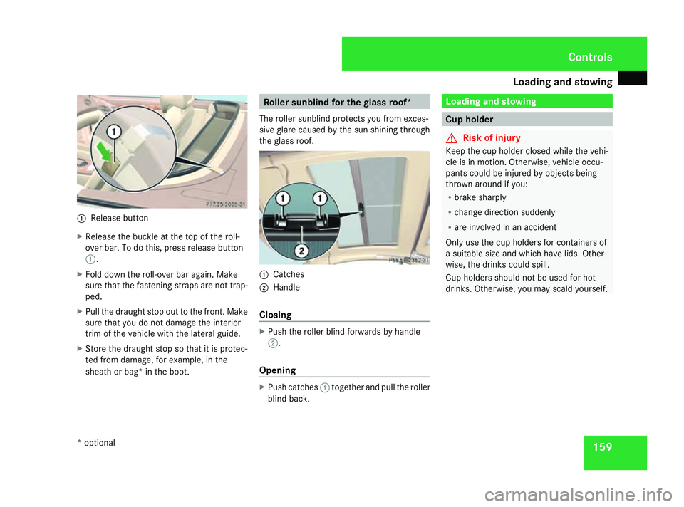
Release button
X Release the buckle at the top of the roll-
over bar. To do this, press release button
1.
X Fold down the roll-over bar again. Make
sure that the fastenin gstraps are not trap-
ped.
X Pull the draught stop out to the front .Make
sure that you do not damage the interior
trim of the vehicle with the lateral guide.
X Store the draught stop so that it is protec-
ted fro mdamage, for example, in the
sheat horb ag* in the boot. Roller sunblind for th
eglass roof*
The roller sunblin dprotect syou fro mexces-
sive glare caused by the sun shining through
the glass roof. 1
Catches
2 Handle
Closing X
Push the roller blind forwards by handle
2.
Opening X
Push catches 1together and pull the roller
blind back. Loading and stowing
Cup holder
G
Risk of injury
Keep the cup holder closed while the vehi-
cle is in motion. Otherwise, vehicle occu-
pant scould be injured by object sbeing
thrown around if you:
R brak esharply
R change direction suddenly
R are involved in an accident
Only use the cup holder sfor containers of
as uitable siz eand which have lids. Other-
wise, the drinks could spill.
Cup holder sshould not be used for hot
drinks. Otherwise, you may scald yourself. Controls
*o ptional
230_AKB; 5; 4, en-GB
bjanott
,V ersion: 2.9.6
2008-04-08T15:09:54+02:00
-Seite 159 ZDateiname: 6515_3089_02_buchblock.pdf; preflight
Page 163 of 317
Loading and stowing
1601
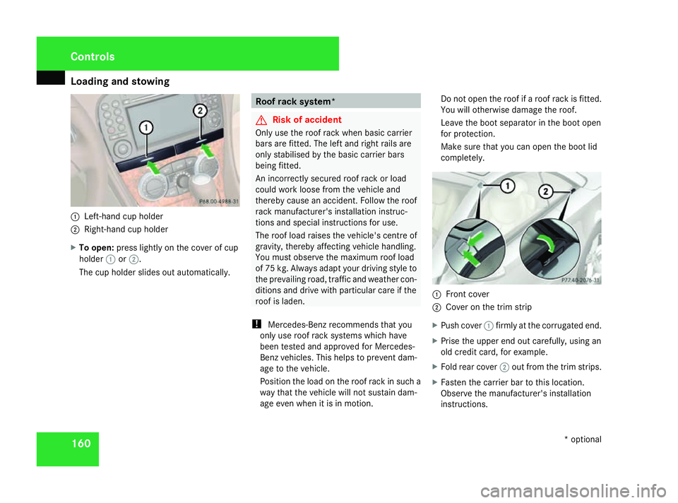
Left-han dcup holder
2 Right-hand cup holder
X To open: press lightly on the cover of cup
holder 1or2.
The cup holder slides out automatically. Roof rack system*
G
Risk of accident
Only use the roof rack when basic carrier
bars are fitted. The left and right rails are
only stabilised by the basic carrier bars
being fitted.
An incorrectly secured roof rack or load
could work loose fro mthe vehicle and
thereby cause an accident .Follow the roof
rack manufacturer' sinstallation instruc-
tion sand special instructions for use.
The roof load raises the vehicle's centr eof
gravity, thereby affectin gvehicle handling.
You must observe the maximum roof load
of 75 kg. Always adapt your driving style to
the prevailing road, traffic and weather con-
ditions and drive with particular care if the
roof is laden.
! Mercedes-Ben zrecommends that you
only use roof rack systems which have
been tested and approved for Mercedes-
Ben zvehicles. This helps to prevent dam-
age to the vehicle.
Position the load on the roof rack in such a
way that the vehicle will not sustain dam-
age even when it is in motion. Do not open the roof if
aroof rack is fitted.
You will otherwise damage the roof.
Leave the boot separator in the boot open
for protection.
Make sure that you can open the boot lid
completely. 1
Front cover
2 Cover on the trim strip
X Push cover 1firmly at the corrugated end.
X Prise the upper end out carefully, using an
old credit card, for example.
X Fold rear cover 2out fro mthe trim strips.
X Fasten the carrier bar to thi slocation.
Observe the manufacturer' sinstallation
instructions. Controls
*optional
230_AKB; 5; 4, en-GB
bjanott ,V ersion: 2.9.6
2008-04-08T15:09:54+02:00
-Seite 160 Dateiname: 6515_3089_02_buchblock.pdf; preflight
Page 164 of 317
Loading and stowing
161G
Ris
kofi njury
Only use th eroofrac kw hen th eroofis
closed. The roo frac kort heload could
endanger th eoccupant softhevehicle
when th eroofiso pen. Luggage net in th
efront-passenger
footwell G
Ris
kofi njury
Only plac elightweigh titems in th eluggage
net. Do no tuse it to transpor theavy, bulky,
sharp-edged or fragile objects. In th eevent
of an accident, th eluggage ne twill not
secure th etransporte dgoods. Stowage well under th
eboot floor
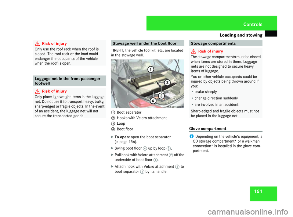
TIREFIT, th evehicle tool kit ,etc.a re located
in th estowage well. 1
Boot separator
2 Hook swith Velcro attachment
3 Loop
4 Boot floor
X To open: open the boot separator
(Y page 156).
X Swin gboot floor 4up by loop 3.
X Pull hook with Velcro attachment 2off the
underside of boot floor 4.
X Attac hhook with Velcro attachment 2to
boot separator 1by its handle. Stowage compartments
G
Risk of injury
The stowage compartments must be closed
when item sare stored in them. Luggage
net sare not designed to secur eheavy
item sofl uggage.
You or other vehicle occupant scould be
injured by object sbeing thrown around if
you:
R brak esharply
R change direction suddenly
R are involved in an accident
Sharp-edged and fragile object smust not
be placed in the luggage net.
Glove compartment i
Depending on the vehicle's equipment, a
CD storage compartment* or awalkman
connection *isinstalled in the glove com-
partment. Controls
230_AKB; 5; 4, en-GB
bjanott
,V ersion: 2.9.6
2008-04-08T15:09:54+02:00
-Seite 161 ZDateiname: 6515_3089_02_buchblock.pdf; preflight
Page 165 of 317
Loading and stowing
1621
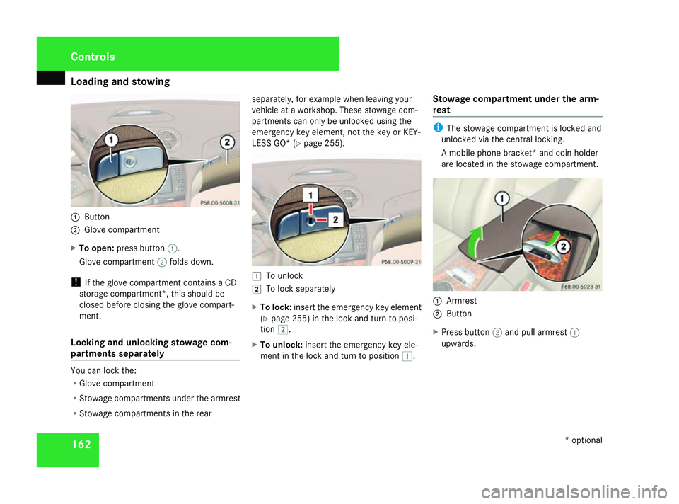
Button
2 Glove compartment
X To open: press button 1.
Glove compartment 2folds down.
! If the glove compartmen tcontain saCD
storage compartment* ,thiss hould be
closed befor eclosing the glove compart-
ment.
Locking and unlocking stowage com-
partment sseparately You can lock the:
R
Glove compartment
R Stowage compartments under the armrest
R Stowage compartments in the rear separately, for example when leavin
gyour
vehicle at aworkshop. These stowage com-
partments can only be unlocked using the
emergenc ykey element, not the key or KEY-
LESS GO* (Y page 255). $
To unlock
% To lock separately
X To lock: insert the emergenc ykey element
(Y page 255 )inthe lock and tur ntoposi-
tion %.
X To unlock: insert the emergenc ykey ele-
men tint he lock and tur ntoposition $. Stowage compartment under th
earm-
rest i
The stowage compartmen tislocked and
unlocked via the central locking.
Am obile phon ebracket* and coin holder
are located in the stowage compartment. 1
Armrest
2 Button
X Press button 2and pull armrest 1
upwards. Controls
*optional
230_AKB; 5; 4, en-GB
bjanott ,V ersion: 2.9.6
2008-04-08T15:09:54+02:00
-Seite 162 Dateiname: 6515_3089_02_buchblock.pdf; preflight