2008 MERCEDES-BENZ SL ROADSTER height
[x] Cancel search: heightPage 77 of 317
Seats
74 Seats
Points to remember
G
Risk of injury
The seats can still be adjusted when there
is no key in the ignition lock. For this rea-
son, children should never be left unsuper-
vised in the vehicle. They could become
trapped when adjusting aseat. G
Risk of accident
Only adjust the driver's seat when the vehi-
cle is stationary. You will otherwise be dis-
tracted from the road and traffic conditions
and you could lose control of the vehicle as
ar esult of the seat moving. This could
cause an accident. G
Risk of injury
Make sure that nobody can become trap-
ped when you adjust the seat.
Observe the notes concerning the airbag
system.
Secure children as recommended; see
"Children in the vehicle" section.
! When you move the seats, make sure that
there are no objectsint he footwell orbehind the seats. Otherwise, you could
damage the seats and the objects.
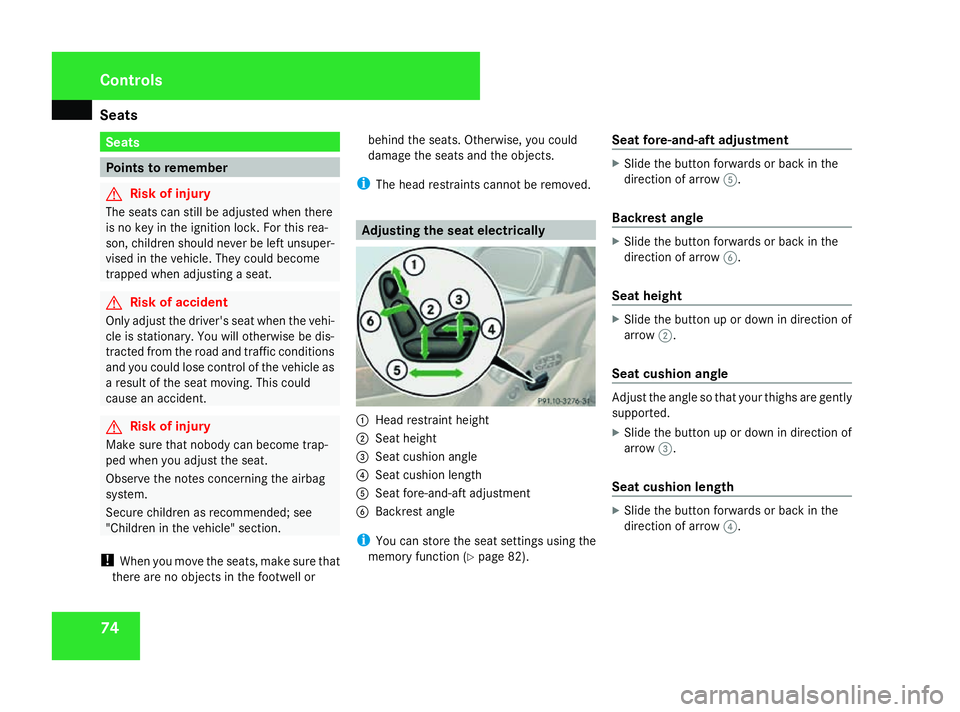
i The head restraint scannot be removed. Adjusting the seat electrically
1
Head restraint height
2 Seat height
3 Seat cushion angle
4 Seat cushion length
5 Seat fore-and-aft adjustment
6 Backrest angle
i You can store the seat settings using the
memory function (Y page 82). Seat fore-and-aft adjustment X
Slide the button forwards or back in the
direction of arrow 5.
Backrest angle X
Slide the button forwards or back in the
direction of arrow 6.
Seat height X
Slide the button up or down in direction of
arrow 2.
Seat cushiona ngle Adjust the angle so that yourt
highs are gently
supported.
X Slide the button up or down in direction of
arrow 3.
Seat cushionl ength X
Slide the button forwards or back in the
direction of arrow 4. Controls
230_AKB; 5; 4, en-GB
bjanott,
Version: 2.9.6
2008-04-08T15:09:54+02:00
-Seite 74 Dateiname: 6515_3089_02_buchblock.pdf; preflight
Page 78 of 317
Seats
75
Head restraint height G
Risk of injury
Make sure that the central area of the head
restraint supports the back of your head at
about eye level. You could seriously injure
your neck if your head is not correctly sup-
ported by the head restraint in the event of
an accident. Never travel without acor-
rectly adjusted and engaged head restraint.
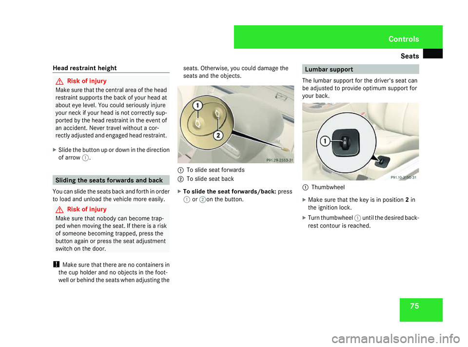
X Slide the button up or down in the direction
of arrow 1. Sliding the seats forwardsa
nd back
You can slide the seats back and forth in order
to load and unload the vehicle more easily. G
Risk of injury
Make sure that nobody can become trap-
ped when moving the seat. If there is arisk
of someone becoming trapped, press the
button again or press the seat adjustment
switch on the door.
! Make sure that there are no containers in
the cup holder and no objectsint he foot-
well or behind the seats when adjusting the seats. Otherwise, you could damage the
seats and the objects.
1
To slide seat forwards
2 To slide seat back
X To slide the seat forwards/back: press
1 or2on the button. Lumbar support
The lumbar support for the driver's seat can
be adjusted to provide optimum support for
your back. 1
Thumbwheel
X Make sure that the key is in position 2in
the ignition lock.
X Turn thumbwheel 1until the desired back-
rest contour is reached. Controls
230_AKB; 5; 4, en-GB
bjanott
,V ersion: 2.9.6
2008-04-08T15:09:54+02:00
-Seite 75 ZDateiname: 6515_3089_02_buchblock.pdf; preflight
Page 82 of 317
Steering wheel
79
R
the steering wheel can be reached with
your arms slightly bent
R you can move your legs freely
R you can see all the displaysint he instru-
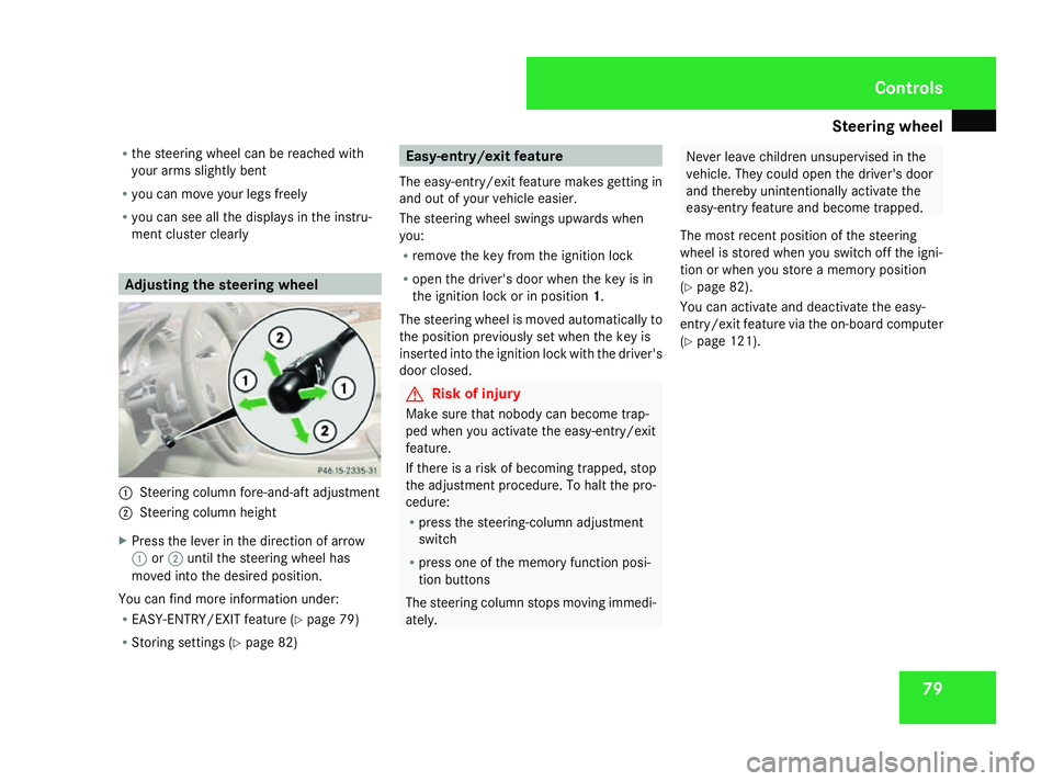
ment cluster clearly Adjusting the steering wheel
1
Steering column fore-and-aft adjustment
2 Steering column height
X Press the lever in the direction of arrow
1 or2 until the steering wheel has
moved into the desired position.
You can find more information under:
R EASY-ENTRY/EXIT feature (Y page 79)
R Storing settings (Y page 82) Easy-entry/exit feature
The easy-entry/exit feature makes getting in
and out of yourv ehicle easier.
The steering wheel swings upwards when
you:
R remove the key from the ignition lock
R open the driver's door when the key is in
the ignition lock or in position 1.
The steering wheel is moved automatically to
the position previously set when the key is
inserted into the ignition lock with the driver's
door closed. G
Risk of injury
Make sure that nobody can become trap-
ped when you activate the easy-entry/exit
feature.
If there is arisk of becoming trapped, stop
the adjustment procedure .Tohalt the pro-
cedure:
R press the steering-column adjustment
switch
R press one of the memory function posi-
tion buttons
The steering column stops moving immedi-
ately. Never leave children unsupervised in the
vehicle. They could open the driver's door
and thereby unintentionally activate the
easy-entryf
eature and become trapped.
The most recent position of the steering
wheel is stored when you switch off the igni-
tion or when you store amemory position
(Y page 82).
You can activate and deactivate the easy-
entry/exit feature via the on-board computer
(Y page 121). Controls
230_AKB; 5; 4, en-GB
bjanott,
Version: 2.9.6
2008-04-08T15:09:54+02:00
-Seite 79 ZDateiname: 6515_3089_02_buchblock.pdf; preflight
Page 142 of 317
Driving sys
tems 139
R
the vehicl eisatresta nd the brake peda lis
depresse d(left foot)
R the gear selector lever is in position D.
Activating RACE START X
Depres sthe brake peda lwithy ourlef tf oot,
kee pitd epressed.
X Turn the progra mselect or switch clock-
wise (Y page 101) ,unti lthe RS lamp lights
up.
Th eleft-hand multi-functio ndisplay shows
the RACESTART Cancel Paddle DOWN
message and the right-hand displa yshows
the RACESTART Confir mPaddle UP
message.
X To cancel :pullt he left paddle
(Y page 102).
or
X To confirm: pull the righ tpaddle
( Y page 102).
Th eleft-hand multi-functio ndisplay shows
the RACESTART message and the right-
hand displa yshows the Depressaccel
pedal message. X
Depres sthe accelerator peda lfully.
Th ee ngine spee drises to approximately
4,000 rpm.
Th eleft-hand multi-functio ndisplay shows
the RACESTART message and the right-
hand multi-functio ndisplay shows the
Releas ebrake to start message.
X Take your foo toff the brake, bu tkeept he
accelerator peda ldep ressed.
Th ev ehicl epulls away at maximum accel-
eration.
Th eleft-hand multi-functio ndisplay shows
the RACESTART message and the right-
hand multi-functio ndisplay shows the
active message.
RAC ESTAR Tisd eactivate dwhent he vehicle
reache saspeed of approximately 50 km/h.
Drive program S+is activated. ESP ®
Sport
remains activated.
i If RAC ESTAR Tisu sedr epeatedly in a
short period of time, it is onl yavailable
agai nafter having driven the vehicl eacer-
tai nd istance. Activ
eBodyC ontrol* (ABC)
Vehicle level Your vehicl
eautomaticall yadjusts its ride
height to reduc epetrol consumption and
improve driving safety.
Depending on the vehicl eheight thathas
been set, the vehicl eautomaticall yadjusts its
height according to the current speed. The
vehicl eislower ed as the spee dincreases. As
the spee disreduced ,the vehicl eisraisedup
to the se tvehicl eheight. G
Ris
kofi njury
SL 63 AMG ,SL65AMG:
Th ev ehicl eislower ed fro mthe normal level
when the engine is switched off .Makes ure,
therefore ,tha tn obod yisint he vicinity of
the whee lhousin goru nder the vehicle
when yo uswitch off the engine .Otherwise,
limbs could becom etrapped.
! SL 63 AMG ,SL65AMG:
Th ev ehicl eislower ed fro mthe normal level
when the engine is switched off .Makes ure
when parking tha tyou positio nyourvehicle
so tha titdoesn ot make contact with the
kerb as it descends .Otherwise, the vehicle
could be damaged. Controls
*o ptional
230_AKB; 5; 4, en-GB
bjanott,
Version: 2.9.6 2008-04-08T15:09:54+02:00-Seite 139 ZDateiname: 6515_3089_02_buchblock.pdf; preflight
Page 143 of 317
Driving sys
tems 140
SL 63 AMG
,SL65AMG:the vehicl eisauto-
maticall ylower ed fro mthe normal level when
the engine is switched off .The vehicl eislow-
ere dapproximately 15 mm at the front and
approximately 10 mm at the rear. Settin
gthe vehicl elevel G
Ris
kofi njury
Make sure tha tnobod yisint he vicinity of
the whee lhousin goru nder the vehicle whil
elowerin gthe vehicl ewhenitiss ta-
tionary. Otherwise, limbs could become
trapped.
Th ef ollowing vehicl eheight scan be set: Vehicle height Suitabl
efor Height above normal at
as
tandstill Automatic lowering Indicato
rlamps Normal Norma
lope ration None 15 mm at most Both off
Heigh
t1 Use of sno
wchains Approx. 25 mm 25 mm at most One on
Heigh
t2 Very uneven roads Approx. 50 mm 50 mm at most Both on
i
Thec hange is so slight tha tyou maynot
notice any difference.
Onl yuseheight 1and height 2whenn eces-
sary .Otherwis efuelconsumption increases
and the handling is affected.
Your selectio nremains saved eve nwheny ou
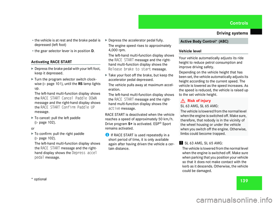
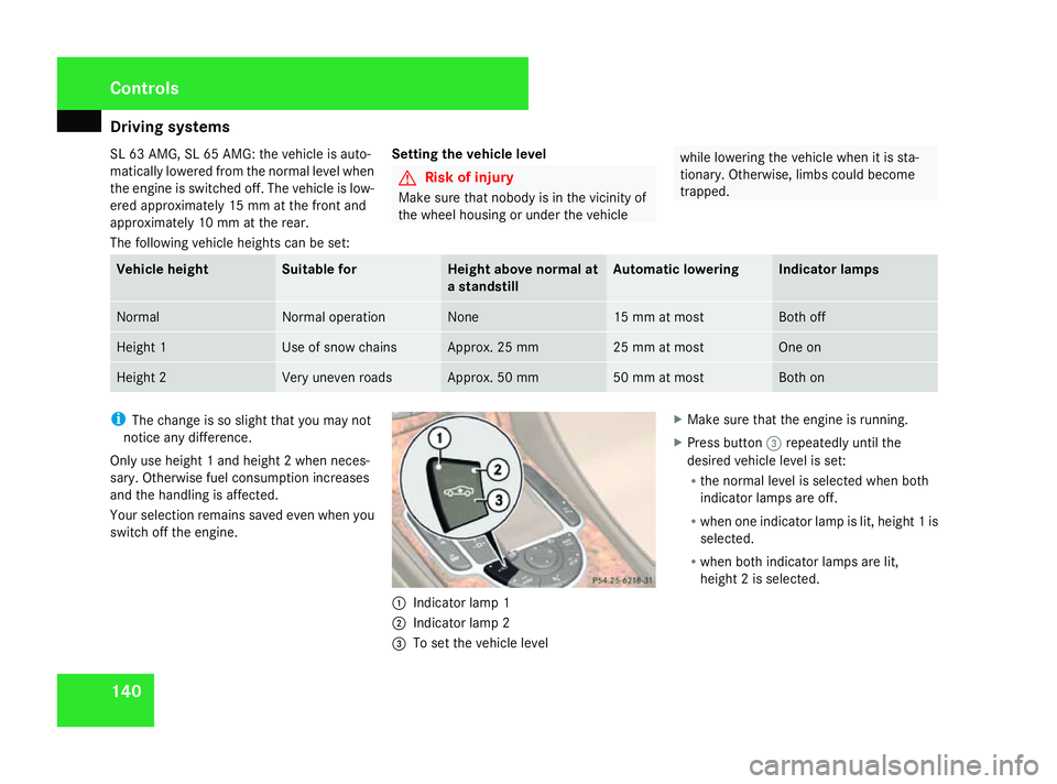
switch off the engine. 1
Indicator lamp 1
2 Indicator lamp 2
3 To se tthe vehicl elevel X
Make sure tha tthe engine is running.
X Press button 3repeatedly unti lthe
desired vehicl elevel is set:
R the normal level is selected when both
indicator lamps ar eoff.
R when one indicator lamp is lit, height 1is
selected.
R when both indicator lamps ar elit,
height 2isselected. Controls
230_AKB; 5; 4, en-GB
bjanott,
Version: 2.9.6
2008-04-08T15:09:54+02:0
0-Seite 140 Dateiname: 6515_3089_02_buchblock.pdf; preflight
Page 180 of 317
Engine compartment
177The electronic ignition system uses high
voltage. Fo rthisr eason ,you must never
touch component softheignition system
(ignition coil, ignition cable, spar kplug con-
nector or test socket) when:
R thee ngineisr unning
R thee ngineisb eingstarted
R thei gnition is switched on and th eengine
is bein gcranked by hand
X Mak esure that th ewindscree nwiper sare
switched off. G
Ris
kofi njury
The windscree nwiper sand wiper linkage
could be set in motion.
When th ebonne tisopen,you or others
could be injured by th ewiper rods.
Mak esure that th ewindscree nwiper sare
switched off and that th ekeyhas been
pulled out of th eignition loc kbefore open-
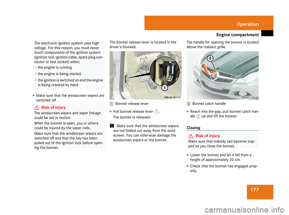
ing th ebonnet. The bonne
trelease leve rislocate dinthe
driver' sfootwell. 1
Bonnet releas elever
X Pull bonnet releas elever 1.
The bonnet is released.
! Make sure that th ewindscreen wipers
are not folde dout away fro mthewind-
screen. You can otherwise damage the
windscreen wipers or th ebonnet. The handl
efor opening th ebonnet is located
above th eradiator grille. 2
Bonnet catch handle
X Reach int othe gap, pull bonnet catch han-
dle 2up and lift th ebonnet.
Closing G
Risk of injury
Make sure that nobody can become trap-
ped as you clos ethe bonnet.
X Lower th ebonnet and let it fall fro ma
height of approximately 20 cm.
X Check that th ebonnet has engaged prop-
erly. Operation
230_AKB; 5; 4, en-GB
bjanott
,V ersion: 2.9.6
2008-04-08T15:09:54+02:00
-Seite 177 ZDateiname: 6515_3089_02_buchblock.pdf; preflight
Page 203 of 317
Where will
Ifind...? 200 Where will
Ifind...? Warning triangle
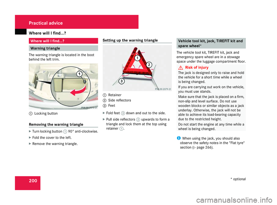
The warning triangl eislocated in the boot
behind the left trim. 1
Locking button
Removin gthe warning triangle X
Turn locking button 190° anti-clockwise.
X Fold the cover to the left.
X Remove the warning triangle. Setting up the warning triangle 1
Retainer
2 Side reflectors
3 Feet
X Fold feet 3dow nand ou ttothe side.
X Pull sid ereflectors 2upwards to form a
triangle and lock them at the top using
retainer 1. Vehicl
etoolkit, jack, TIREFI Tkit and
spare wheel*
The vehicle tool kit, TIREFIT kit, jack and
emergency spare wheel are in astowage
space under the luggage compartment floor. G
Risk of injury
The jack is designe donly to raise and hold
the vehicle for ashort time whileaw heel
is being changed.
If yo uare carrying ou tworkont he vehicle,
yo um ustu se stands.
Make sure that the jack is place donafirm,
non-sli pand level surface .Donot use
woode nblocks or similar objects as ajack
underlay .Otherwise, the jack will not be
able to achiev eits load-bearing capacity
du etot he restricted height.
Do not start the engine at any time whilea
wheel is being changed.
i Whe nusing the jack, yo ushoul dalso
observe the safety notes in the "Flat tyre"
section (Y page 266). Practical advice
*optional
230_AKB; 5; 4, en-GB
bjanott,
Version: 2.9.6 2008-04-08T15:09:54+02:00-Seite 200 Dateiname: 6515_3089_02_buchblock.pdf; preflight
Page 274 of 317
Flat tyre
271The vehicl
emustbep laced on stand sifyou
intend to wor kunder it.
Mak esuret hatthe jackisp laced on afirm,
non-slip ,level surface. Do no tuse wooden
blocks or similar items as jacking supports.
Otherwise ,the jackw ill no tbea ble to ach-
iev eits load-bearin gcapacity due to the
restricted height.
Do no tstart th eengineata ny time while
th ew hee lisb eingchanged. G
Risk of accident
If you fail to position th ejackc orrectly,t he
vehicl emay:
R slip of fthe jack
R injur eyou or others
R be damaged
It is thus important to ensur ethatthe jack
is positioned correctl yint he respective
jacking points .Befor epositionin gthe jack,
remove any dir ttha tm ay hav ecollecte din
th ej acking points.
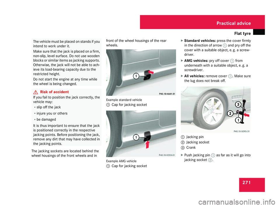
The jacking sockets are locate dbehin dthe
whee lhousings of th efront wheels and in fron
toft hewhee lhousings of th erear
wheels. Example standar
dvehicle
1 Cap for jackin gsocket Example AMG vehicle
1
Cap for jackin gsocket X
Standar dvehicles: pressthe cover firmly
in th edirectio nofarrow1and pry off the
cover with asuitable object ,e.g.a screw-
driver.
X AMG vehicles: pry off cover1from
underneat hwithasuitable object ,e.g.a
screwdriver.
X All vehicles: remove cover 1.Make sure
th el ug does not break off. 1
Jacking pin
2 Jacking socket
3 Crank
X Push jackin gpin1 as far as it will go into
jackin gsocket 2. Practical advice
230_AKB
;5;4,en-GB
bjanott, Version:2.9.6
2008-04-08T15:09:54+02:00
-Seite 271 ZDateiname: 6515_3089_02_buchblock.pdf; preflight