Page 471 of 569
470 Practical hints
Where will I find ...?
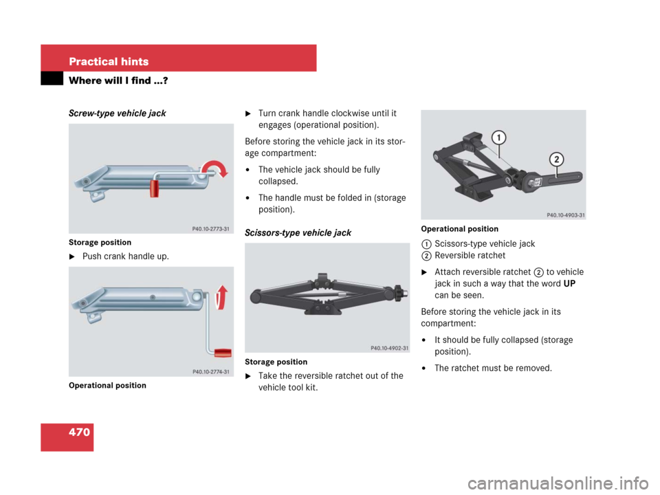
Screw-type vehicle jack
Storage position
�Push crank handle up.
Operational position
�Turn crank handle clockwise until it
engages (operational position).
Before storing the vehicle jack in its stor-
age compartment:
�The vehicle jack should be fully
collapsed.
�The handle must be folded in (storage
position).
Scissors-type vehicle jack
Storage position
�Take the reversible ratchet out of the
vehicle tool kit.
Operational position
1Scissors-type vehicle jack
2Reversible ratchet
�Attach reversible ratchet2 to vehicle
jack in such a way that the wordUP
can be seen.
Before storing the vehicle jack in its
compartment:
�It should be fully collapsed (storage
position).
�The ratchet must be removed.
Page 473 of 569
.
Removin")
472 Practical hints
Where will I find ...?
Your vehicle is equipped with a spare
wheel with collapsible tire. The spare
wheel is located underneath the cargo
compartment floor (
�page 467).
Removing the spare wheel
1Retaining screw
2Spare wheel
3Vehicle tool kit storage well casing
�Remove the jack from the vehicle tool
kit (
�page 469).
�Loosen retaining screw 1 by turning it
counterclockwise.
�Turn vehicle tool kit storing well
casing3 by approximately 180°.
The electric air pump (
�page 469)
points towards the rear.
�Remove vehicle tool kit storage well
casing 3.
�Remove spare wheel 2.
Reinstalling the spare wheel after use
There are two guide pins in the spare wheel
well that serve to hold the spare wheel in
place.1Guide pins
1Guide pins
2Spare wheel
iFor information on how to mount the spare
wheel, see “Mounting the spare wheel”
(
�page 493).
iIf retaining screw 1 does not come loose,
turn vehicle tool kit storing well casing 3 slightly
counterclockwise. Retaining screw 1 should
then come loose easily.
Page 474 of 569
473 Practical hints
Where will I find ...?
�Place spare wheel 2 into spare wheel
well.
Make sure spare wheel 2 is placed
precisely on guide pins 1.
�Insert vehicle tool kit storage well
casing 3 (
�page 472) into spare
wheel 2.
The electric air pump (
�page 469)
must point to the rear.
�Turn vehicle tool kit storing well
casing3 (
�page 472) by approxi-
mately 180°.
The electric air pump (
�page 469)
points in direction of travel.
�Fasten retaining screw 1
(
�page 472) by turning it clockwise.
�Insert the jack into the vehicle tool kit
storage well casing (
�page 469).
�Close and pull tight the hook and
loop fastener that secures the
jack (
�page 469).
iThe vehicle tool kit storage well casing
should now be positioned according to mounting
direction indicators 3 (
�page 469).
Page 475 of 569
474 Practical hints
Unlocking / locking in an emergency
Unlocking the vehicle
If you cannot unlock the vehicle with the
SmartKey or KEYLESS-GO*, open the
driver’s door using the mechanical key.Removing the mechanical key
1Mechanical key locking tab
2Mechanical key
�Move locking tab1 in direction of
arrow.
�Slide mechanical key2 out of the
housing.Unlocking the driver’s door
�Insert mechanical key 2 into the
driver’s door lock until it stops.
�Turn mechanical key 2 counterclock-
wise to position1 and hold it there.
�Pull the door handle until the locking
knob moves up.
The driver’s door is unlocked.
�Pull the door handle once more to open
the driver’s door.
iUnlocking the driver’s door with the
mechanical key will trigger the anti-theft
alarm system.
To cancel the alarm, insert the SmartKey or
SmartKey with KEYLESS-GO* in the starter
switch.
1Unlocking
2Mechanical key
Page 477 of 569
476 Practical hints
Unlocking / locking in an emergency
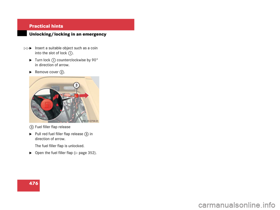
�Insert a suitable object such as a coin
into the slot of lock1.
�Turn lock1 counterclockwise by 90°
in direction of arrow.
�Remove cover2.
3Fuel filler flap release
�Pull red fuel filler flap release 3 in
direction of arrow.
The fuel filler flap is unlocked.
�Open the fuel filler flap (�page 352).
��
Page 484 of 569
483 Practical hints
Replacing bulbs
Replacing bulbs for front lamps
Before you start to replace a bulb for a
front lamp, do the following first:
�Turn the exterior lamp switch to
positionM (
�page 143).
�Open the hood (�page 356).
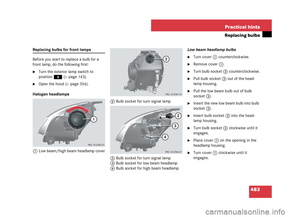
Halogen headlamps
1Low beam/high beam headlamp cover2Bulb socket for turn signal lamp
2Bulb socket for turn signal lamp
3Bulb socket for low beam headlamp
4Bulb socket for high beam headlampLow beam headlamp bulbs
�Turn cover 1 counterclockwise.
�Remove cover 1.
�Turn bulb socket 3 counterclockwise.
�Pull bulb socket 3 out of the head-
lamp housing.
�Pull the low beam bulb out of bulb
socket 3.
�Insert the new low beam bulb into bulb
socket 3.
�Insert bulb socket 3 into the head-
lamp housing.
�Turn bulb socket 3 clockwise until it
engages.
�Place cover 1 on the opening in the
headlamp housing.
�Turn cover 1 clockwise until it
engages.
Page 485 of 569
484 Practical hints
Replacing bulbs
High beam headlamp bulbs
�Turn cover 1 counterclockwise.
�Remove cover 1.
�Turn bulb socket 4 counterclockwise.
�Pull bulb socket 4 out of the head-
lamp housing.
�Pull the high beam bulb out of bulb
socket 4.
�Insert the new high beam bulb into bulb
socket 4.
�Insert bulb socket 4 into the head-
lamp housing.
�Turn bulb socket 4 clockwise until it
engages.
�Place cover 1 on the opening in the
headlamp housing.
�Turn cover 1 clockwise until it
engages.Front turn signal lamp bulbs
�Pull bulb socket 2 out of the head-
lamp housing.
�Pull the turn signal bulb out of bulb
socket 2.
�Insert the new turn signal bulb into bulb
socket 2.
�Insert bulb socket 2 into the head-
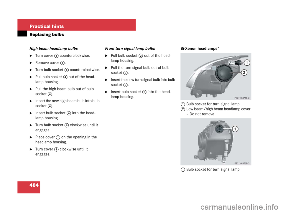
lamp housing.Bi-Xenon headlamps*
1Bulb socket for turn signal lamp
2Low beam/high beam headlamp cover
– Do not remove
1Bulb socket for turn signal lamp
Page 486 of 569

485 Practical hints
Replacing bulbs
Low beam and high beam flasher spot
bulbs
Front turn signal lamp bulbs
�Pull bulb socket 1 out of the head-
lamp housing.
�Pull the turn signal bulb out of bulb
socket 1.
�Insert the new turn signal bulb into bulb
socket 1.
�Insert bulb socket 1 into the head-
lamp housing.Parking and standing lamp bulbs
1Bulb socket for parking and standing
lamp
�Turn bulb socket 1 counterclockwise.
�Pull bulb socket 1 out of the housing.
�Pull the bulb out of bulb socket 1.
�Insert the new parking and standing
lamp bulb into bulb socket 1.
�Insert bulb socket 1 into the housing.
�Turn bulb socket 1 clockwise until it
engages.Front fog lamp bulbs
1Front fog lamp
2Cover
3Retaining screws
�Remove retaining screws3.
�Take off cover 2.
Warning!G
Do not remove the low beam/high beam
cover for the Bi-Xenon* headlamp. Because
of high voltage in Bi-Xenon* lamps, it is dan-
gerous to replace the bulb or repair the lamp
and its components. We recommend that
you have such work done by a qualified
technician.
iThe following procedure also applies to
corner-illuminating front fog lamps*.
��